GF 604 Bedienungsanleitung

Verwandte Anleitungen für GF 604


Inhaltszusammenfassung für GF 604
- Seite 1 GF Piping Systems Bedienungsanleitung Instruction Manual Membranventil Typ 604/605 Diaphragm valve type 604/605...
-
Seite 2: Originalbetriebsanleitung
Originalbetriebsanleitung Bedienungsanleitung Deutsch Membranventil Typ 604/605…………………………………………………………………………………………………….5 English Diaphragm valve type 604/605……………………………………………………………………………………………….26 The instruction manuals in languages French and Spanish are online available at www.gfps.com/dv. - Seite 3 Bedienungsanleitung Originalbetriebsanleitung Originalbetriebsanleitung Betriebsanleitung beachten Die Betriebsanleitung ist Teil des Produkts und ein wichtiger Baustein im Sicherheitskonzept. Betriebsanleitung lesen und befolgen. Betriebsanleitung stets am Produkt verfügbar halten. Betriebsanleitung an alle nachfolgenden Verwender des Produkts weitergeben.
-
Seite 4: Inhaltsverzeichnis
Inhaltsverzeichnis Bedienungsanleitung Inhaltsverzeichnis Originalbetriebsanleitung ....................... 4 Inhaltsverzeichnis ..........................6 Bestimmungsgemässe Verwendung ..................8 Zu diesem Dokument ......................8 Warnhinweise ........................8 Mitgeltende Dokumente ......................9 Beschriebene Produktvarianten und Typen ................. 9 Abkürzungen .......................... 9 Sicherheit und Verantwortung ....................9 Transport und Lagerung ......................10 Aufbau und Funktion ......................10 Aufbau ...........................10 Funktionsweise ........................11... - Seite 5 Bedienungsanleitung Inhaltsverzeichnis Ersatzteilliste ........................22 Zubehör ..........................22 Entsorgung ..........................22...
-
Seite 6: Bestimmungsgemässe Verwendung
Die nachfolgenden Beschreibungen und Anweisungen gelten für das pneumatische Membranventil Typ 604/605 mit Funktion FC, FO oder DA. Das pneumatische Membranventil Typ 604/605 ist ausschliesslich dazu bestimmt, nach Einbau in ein Rohrleitungssystem Medien innerhalb der zugelassenen Druck- und Temperaturgrenzen abzusperren, durchzuleiten oder den Durchfluss zu regeln. -
Seite 7: Mitgeltende Dokumente
W W eitere Auszeichnungen Symbol Bedeutung Handlungsaufforderungen in einer nummerierten Handlungsabfolge Handlungsaufforderungen Aufzählung Mitgeltende Dokumente Georg Fischer Planungsgrundlagen Industrie Diese Unterlagen sind über die Vertretung von GF Piping Systems oder unter www.gfps.com erhältlich. Beschriebene Produktvarianten und Typen Merkmal – Anschlussvariante Verschraubung Stutzen Abkürzungen Abkürzung... -
Seite 8: Transport Und Lagerung
Transport und Lagerung Bedienungsanleitung Transport und Lagerung Das Produkt muss sorgfältig behandelt, transportiert und gelagert werden. Hierzu sind folgende Punkte zu beachten: Produkt beim Transport gegen äussere Gewalt (Stoss, Schlag, Vibrationen etc.) schützen. Produkt in ungeöffneter Originalverpackung transportieren und lagern. Sicherstellen, dass das Produkt weder durch mechanische noch durch thermische Einflüsse beschädigt werden kann. -
Seite 9: Funktionsweise
Funktionsweise 5.2.1 Membranventil mit Funktion FC Zur Ansteuerung einfach wirkender Antriebe mit Funktion FO: 3/2 Wege Vorsteuerventile verwenden, z. B. GF Typ PV 94. Steuermedium je nach Bedarf über eine Hohlschraube direkt am Stellantrieb oder abgesetzt über Mehrfachanschlussplatte bzw. Ventilinsel anschliessen. -
Seite 10: Identifikation
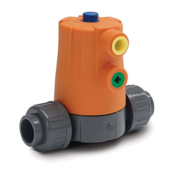
Aufbau und Funktion Bedienungsanleitung Identifikation 5.3.1 Membranventil Typenschild Pos. Name Pos. Name Ventilkörperwerkstoff Max. Steuerdruck Bestellnummer Dimension Funktionsweise Nenndruck Seriennummer Membranwerkstoff CE-Kennzeichnung 5.3.2 Identifikation Ventilkörper T T yp 6 6 04 – – A A nschluss: Verschraubung T T yp 6 6 05 – – A A nschluss: Stutzen 5.3.3 Membranwerkstoff Der Membranwerkstoff ist anhand der Einfärbung des Rasterelements am Ventilkörper zu erkennen. -
Seite 11: Technische Daten
Steuerdrücke gewählt werden Anschluss Steuermedium VORSICHT Beschädigung des Membranventils durch mangelhafte Installation! Die Leitung des Steuermediums ist spannungs- und knickfrei zu montieren! d20/DN15 G 1/4“ Steuervolumen und Steuerdruck Funktion Typ 604/605 (Membran) Steuerdruck Steuervolumen Mediumsdruck d20 DN15 [bar] [bar] [dm³] FC (EPDM, FKM) 0.018... -
Seite 12: Druckstufe
Installation Bedienungsanleitung Druckstufe Baureihe Typ 604/605 Unterteil- PVC-U, PVC-C, ABS*, PVC-U, PVC-C, ABS*, PVC-U, PVC-C, ABS*, Werkstoff** PP-H, PVDF PP-H, PVDF PP-H, PVDF EPDM PTFE EPDM PTFE EPDM PTFE Druckstufe [bar] [bar] [bar] [bar] [bar] [bar] [bar] [bar] [bar] d20/DN15 * auf Anfrage ** Informationen zur Temperaturbeständigkeit auf www.gfps.com/dv... -
Seite 13: Montage
Bedienungsanleitung Inbetriebnahme Montage VORSICHT Verletzungsgefahr durch mangelhafte Installation! Längs- und Biegekräfte durch Temperaturwechsel verursachen Wärmeausdehnung im Rohrsystem, mit dem Risiko der Beschädigung des Membranventils. Eine der folgenden Montagearten sicherstellen: Membranventil als Festpunkt montieren. Halterungen der Rohrleitung vor und nach dem Membranventil montieren. Membranventil und Rohrleitung so montieren, dass beide fluchten. -
Seite 14: Durchführung Der Druckprobe
Ventilhub reduzieren: Kolben (1) im Uhrzeigersinn mit Schraubenzieher drehen (360° = ~ 1mm Ventilhub) Ventilhub vergrössern: Kolben (1) gegen Uhrzeigersinn mit Schraubenzieher drehen (360° = ~ 1mm Ventilhub) Antrieb Ventilhub Max. Betätigungsmoment Variante SOLL (mm) Newtonmeter [NM] 604/605 * Max. Ventilhub... -
Seite 15: Wartung
Bei Verwendung des Membranventils als Endarmatur: Membranventil NICHT öffnen, solange Leitung unter Druck steht! VORSICHT Verletzungsgefahr und fehlende Produktqualität durch Verwendung von Ersatzteilen, die nicht von GF Piping Systems zur Verfügung gestellt wurden! Verletzungsgefahr und Sachschaden möglich. Ausschliesslich die zugelassenen Ersatzteile verwenden, siehe Kapitel 11 „Ersatzteilliste“, Seite 22. -
Seite 16: Wartungsplan
Wartung Bedienungsanleitung Wartungsplan Wartungsintervalle entsprechend der Einsatzbedingungen festlegen, z. B. Stellzyklen, Medium, Umgebungstemperatur. Im Rahmen der regelmässigen Anlageninspektion folgende Wartungstätigkeiten durchführen: Wartungsintervall Wartungstätigkeit regelmässig Verbindung zwischen Oberteil und Ventilkörper auf Dichtheit prüfen regelmässig Membranen sind Verschleissteile Membran bei Inbetriebnahme und während des Einsatzes –... - Seite 17 Bedienungsanleitung Wartung W W echseln der PTFE-Membran mit Hinterlagsmembran Spezialwerkzeug: Hakenschlüssel, siehe Kapitel 12 „Zubehör“, Seite 22, oder passender Bandschlüssel Personen- und Sachschäden durch unkontrolliertes Austreten oder Nachfliessen des Mediums aus Leitung oder Ventil! Wenn PTFE-Membranen mit Hinterlagsmembran (in EPDM oder FKM) verwendet werden: Sicherstellen, dass beide Membranen ausgewechselt werden.
- Seite 18 Wartung Bedienungsanleitung Rasterelement am Ventilkörper mit Schraubendreher lösen und entfernen. Zur neuen Membran passendes Rasterelement (im Lieferumfang Ersatzmembran enthalten) eindrücken. (Vgl. Kapitel 5.3.3 Membranwerkstoff) Sicherstellen, dass der Dichtungs-O-Ring zwischen Innengehäuse und Ventil vorhanden und frei von Rissen ist. Ventilkörper auf Oberteil setzen und positionieren: Dichtwulst der Membran parallel zum Dichtsteg ausrichten, dabei Ohren der Membran am Ventilkörper ausrichten.
-
Seite 19: Störungsbehebung
Bedienungsanleitung Störungsbehebung Identifikation der Oberteile Bei einer Demontage können die Oberteile wie folgt unterschieden werden: Standard-Luftanschlüsse Luftanschlüsse in Rohrachse Die Aussparung für die Standard Luftanschlüsse ist gegenüber von den Luftanschlüssen, bei den Luftanschlüssen in Rohrachsen ist die Aussparung um 90° versetzt. Störungsbehebung Störung Mögliche Ursache... -
Seite 20: Ersatzteilliste
Ersatzteilliste Bedienungsanleitung Störung Mögliche Ursache Fehlerbehebung bzw. schliesst oder Funktion und Anschlüsse für Funktion (FC, FO, DA) und öffnet nicht Steuermedium passen nicht zugehörige Anschlüsse zusammen überprüfen, siehe Kapitel 5.2 „Funktionsweise“, Seite 11. Defekte Be- und Be-und Entlüftungsleitung Entlüftungsleitung auf Funktion prüfen. Mediumsleckage am Verschleiss der Dichtungen Membranventil austauschen. - Seite 21 Sammlung von Elektro- und Elektronikgeräten zuzuführen. Bei Fragen bezüglich der Entsorgung des Produkts wenden Sie sich an Ihre nationale Vertretung von GF Piping Systems. Bei Fragen bezüglich der Entsorgung des Produkts wenden Sie sich an Ihre nationale Vertretung von GF Piping Systems.
-
Seite 22: Hersteller
R&D Manager Georg Fischer Piping Systems Ltd. Ebnatstrasse 111 8201 Schaffhausen / Switzerland Hiermit bestätigen wir, dass die nachstehend vollständige Maschine Membranventil Typ: 604/605 Varianten: fail-safe to close FC-mode; fail safe-open FO-mode; double acting DA-mode Code: 161604012,161604014,161604015,161604032,161604034,161604035,161604062,161604064, 161604065,161604412,161604414,161604415,161604432,161604434,161604435,161604462, 161604464,161604465,161604512,161604514,161604515,161604532,161604534,161604535, 161604562,161604564,161604565,161604612,161604614,161604615,161604632,161604634,... - Seite 23 Bedienungsanleitung Entsorgung Des Weiteren erklären wir, dass die folgenden sonstigen technischen Normen (oder Teile/Klauseln hiervon) und Spezifikationen angewandt worden sind: NA19 (Luftanschlüsse) Name: Bastian Lübke Position: R&D Manager Georg Fischer Piping Systems Datum: 2017-02-22...