Werbung
Quicklinks
GF Piping Systems
Mounting instructions
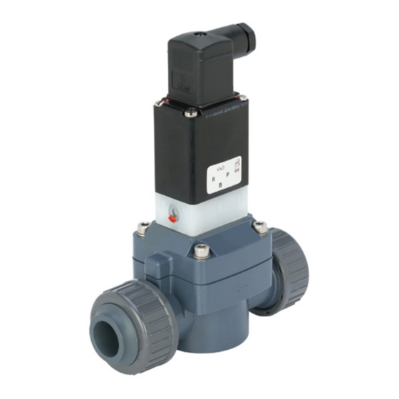
Type 165 2/2-way solenoid valve
Montageanleitung
Typ 165 2/2-Wege-Magnetventil
1271113
MA_00068 / DE EN / 0a (03.2021)
© Georg Fischer Piping Systems Ltd
CH-8201 Schaffhausen/Switzerland
+41 52 631 30 26 / info.ps@georgfischer.com / www.gfps.com
Overview
1
1
Übersicht
2
5
4
Description
Beschreibung
Cable plug in accordance with
Gerätesteckdose nach
a
DIN EN 175301-803, Form A
DIN EN 175301-803, Form A
Type label
Typenschild
s
Manual control
Handbetätigung
d
Flow direction
Durchflussrichtung
f
Pressure connection / Outlet
Druckanschluss/ Ausgang
g
Mounting position
5
Montageposition
Note
Mounting position as desired, actuator preferably upwards.
Hinweis
Einbaulage beliebig, vorzugsweise Antrieb nach oben.
Preparation for electrical connection
9
Vorbereitung für elektrischen Anschluss
165
A 20,0 FKM PV
025
P N 0,5 - 6 bar
230V 50-60 Hz
5 W
00042005
W17MG
WARNING!
Risk of injury due to electrical shock!
► Before reaching into the system, switch off the power supply
and secure to prevent reactivation.
► Note the voltage and current type as specified on the type label.
WARNUNG!
Verletzungsgefahr durch Stromschlag!
► Vor Eingriffen in das Gerät oder die Anlage Spannung
abschalten und vor Wiedereinschalten sichern.
► Spannung und Stromart laut Typschild beachten.
Our General Terms of Sale apply.
Es gelten unsere Allgemeinen Verkaufsbedingungen.
EC declaration of conformity
Georg Fischer Piping Systems Ltd, 8201 Schaffhausen (Switzerland) declares that the
products listed below comply with the requirements of the European Directive(s) and
may therefore bear the CE marking.
Modifications to the products that affect the specified technical data and the intended
use make this declaration invalid.
Additional information can be found in the "GF Planning Fundamentals".
EG-Konformitätserklärung
Georg Fischer Rohrleitungssysteme AG, 8201 Schaffhausen (Schweiz) erklärt, dass
nachfolgend aufgeführte Produkte den Anforderungen der Europäischen Richtlinie(n)
entspricht und somit die CE-Kennzeichnung tragen dürfen.
Änderungen an den Produkten, die Auswirkungen auf die angegebenen technischen
Daten und den bestimmungsgemässen Gebrauch haben, machen diese Erklärung
ungültig.
Zusätzliche Informationen können den «GF Planungsgrundlagen» entnommen werden.
Product group
Type designation
Additional directives and harmonized design
Produktgruppe
Typenbezeichnung
standards
Weitere Richtlinien und Harmonisierte
Bauart-Normen
Solenoid valve
Type 165
2006/95/EG*
2014/30/EU
EN61010-1:2010
EN50178:1997
EN60664-1:2007
EN60204-1:2006
*valid for 100-230V types / *gültig für 100-230V Typen.
Schaffhausen, den 12.03.2021
Bastian Lübke
Head of Global R&D
Georg Fischer Piping Systems Ltd.
CH-8201 Schaffhausen (Switzerland)
Complete technical documentation via QR
code or at
Vollständige technische Dokumentation über
QR-Code oder unter
www.gfps.com/is-solenoid-valves
Operating Instructions_2102/01_Euml_00805744
Type label
2
Typenschild
1
2
3
3
165
A 20,0 FKM PV
025
P N 0,5 - 6 bar
230V 50-60 Hz
00042005
9
5
Description
Beschreibung
Type
Typ
a
Circuit function
Wirkungsweise
s
Nominal diameter
Nennweite
d
Sealing material
Dichtungswerkstoff
f
Body material
Gehäusewerkstoff
g
Connection thread, Operating
Anschlussart, Betriebsdruck
h
pressure
Voltage, Frequency,
Spannung, Frequenz, Leistung
j
Power consumption
Manufacturer code
Hersteller-Code
k
Id. Number
Identnummer
l
Before installation
6
Vor dem Einbau
S
P
Procedure
► Clean any contamination from the pipes.
► Install a dirt filter (S) for particles ≤ 500 μm upstream of the
pressure connection (P).
Vorgehensweise
► Rohrleitungen von eventuellen Verschmutzungen säubern.
► Vor dem Druckanschluss (P) einen Schmutzfilter (S) für Partikel
≤ 500 μm einbauen.
Electrical connection of the cable plug
10
Elektrischer Anschluss der Gerätesteckdose
Procedure
► Connect cable plug to cable (cable cross-section 3 x 0.75 mm²).
► Connect protective conductor and check electrical continuity.
If the protective conductor is not connected, there is a risk of
electric shock!
Vorgehensweise
► Gerätesteckdose an Kabel anschliessen (Kabelquerschnitt 3 x
0,75 mm²).
► Schutzleiter anschliessen und elektrischen Durchgang prüfen.
Bei fehlendem Schutzleiterkontakt zwischen Spule und Gehäuse
besteht die Gefahr des Stromschlags!
Other applicable documents
Planning Fundamentals Industry
Abbreviations
FC
Function Failsafe Closed
FO
Function Failsafe Open
Technical data
Nominal diameter
DN15-50
Housing material
PVC, PVDF
Sealing material
EPDM, FKM
Media
EPDM
Alkalines, detergent and bleach solutions
FKM
Oxidizing acids and substances
Media temperature
PVC
(housing and gasket)
PVDF
Ambient temperature
PVC
PVDF
Viscosity
Max. 21 mm
Supply voltage
24 V / DC, 230 V / 50/60 Hz, 110V 50Hz/60Hz
Voltage tolerance
±10 %
Switching frequency
AC
DC
Rated duty
ED 100 %
Electrical connection
Cable plug, according to DIN EN 175301-803, form A
Protection class
IP65 with cable plug
Circuit functions
3
Wirkungsweisen
4
5
6
5 W
7
Scheme/Schema
Description
W17MG
A
2/2-way valve;
FC; closed in rest
8
position
7
Flow direction
Durchflussrichtung
Note
► Observe direction of flow. The arrow or letter on the body
indicates the direction of flow.
► Functioning of the device is only ensured if the circuit function is
maintained.
Hinweis
► Durchflussrichtung beachten. Der Pfeil bzw. die Buchstaben auf
dem Gehäuse kennzeichnen die Durchflussrichtung.
► Die Funktion des Geräts ist nur sichergestellt, wenn die
Wirkungsweise eingehalten wird.
Mounting the cable plug
11
Montage der Gerätesteckdose
1
Description
Cable plug
a
Seal
s
Max. 1 Nm
d
Procedure
► Tighten cable plug to the device, observing max. torque 1 Nm.
► Check that seal is fitted correctly.
Vorgehensweise
► Gerätesteckdose an Gerät festschrauben, dabei maximales
Drehmoment 1 Nm beachten.
► Korrekten Sitz der Dichtung überprüfen.
N°
i
Mitgeltende Unterlagen
700671687
Planning Fundamentals Industry
Abkürzungen
FC
Wirkungsweise Federkraft schliessend
FO
Wirkungsweise Federkraft öffnend
Technische Daten
Nennweite
Gehäusewerkstoff
Dichtwerkstoff
Medien
0 to +50 °C
Medientemperatur
(Gehäuse und Dichtung)
0 to +70 °C
0 to +40 °C
Umgebungstemperatur
0 to +55 °C
2
/s
Viskosität
Betriebsspannung
Spannungstoleranz
60/min
Schalthäufigkeit
Max. 6/min
Nennbetriebsart
Elektrischer Anschluss
Schutzart
Manual control
4
Handbetätigung
Beschreibung
2/2-Wege-Ventil,
FC; in Ruhestellung
geschlossen
Description
Press
a
Turn
s
Caution
When the manual control is locked, the valve can no longer be
actuated electrically.
Vorsicht
Bei arretierter Handbetätigung kann das Ventil elektrisch nicht
mehr betätigt werden.
Installation
8
Einbau
Description
O-ring
a
Insert
s
Union nut
d
Caution
► Caution risk of breakage! Do not use the coil as a lever arm.
► Valve body must not be installed under tension.
► Use Tangit special adhesive for the PVC bonded sleeves.
► Sealing material must not get into the device.
► Tighten union nut - evenly by hand only
Vorsicht
► Vorsicht Bruchgefahr! Spule nicht als Hebelarm benutzen.
► Ventilgehäuse darf nicht verspannt eingebaut werden.
► Tangit Spezialkleber für die PVC-Klebemuffen verwenden.
► Dichtmaterial darf nicht in das Gerät gelangen.
► Überwurfmutter gleichmässig nur von Hand festziehen.
Malfunctions
12
Störungen
3
► If malfunctions occur, check port connections, operating
pressure and supply voltage. A stuck armature in AC coils
causes coil overheating.
2
Malfunction
Valve does not switch
Valve does not close
► Bei Störungen Anschluss, Betriebsdruck und Spannung
überprüfen. Festsitzender Anker bewirkt bei Wechselstrom-
Beschreibung
spulen Spulenüberhitzung.
Gerätesteckdose
Störung
Dichtung
Ventil schaltet nicht
Max. 1 Nm
Ventil schliesst nicht
i
N°
700671686
DN15-50
PVC, PVDF
EPDM, FKM
EPDM
Alkalien, alkalische Wasch- und Bleichlaugen
FKM
Oxidierende Säuren und Substanzen
PVC
0 bis +50 °C
PVDF
0 bis +70 °C
PVC
0 bis +40 °C
PVDF
0 bis +55 °C
Max. 21 mm
2
/s
24 V / DC, 230 V / 50/60 Hz, 110V 50Hz/60Hz
±10 %
AC
60/min
DC
Max. 6/min
ED 100 %
Gerätesteckdose, nach DIN EN 175301-803, Form A
IP65 mit Gerätesteckdose
1
2
Beschreibung
Drücken
Drehen
1
2
3
Beschreibung
O-Ring
Einlegeteil
Überwurfmutter
Possible cause
Short-circuit or coil interrupted
Medium pressure outside the permitted
pressure range
Manual control locked
Internal space of the valve is dirty
Manual control locked
Flow restrictor (Valve inlet) or pilot holes (valve
inlet/outlet) dirty
Mögliche Ursache
Kurzschluss oder Spulenunterbrechung
Mediumsdruck ausserhalb des zulässigen
Druckbereichs
Handbetätigung arretiert
Innenraum des Ventils verschmutzt
Handbetätigung arretiert
Drossel (Ventileingang) bzw. Vorsteuerbohrun-
gen (Ventil-Eingang/-Ausgang) verschmutzt
Werbung

Verwandte Anleitungen für GF 165


Inhaltszusammenfassung für GF 165
- Seite 1 Type 165 2/2-way solenoid valve Wirkungsweise Federkraft öffnend Function Failsafe Open Additional information can be found in the “GF Planning Fundamentals”. EG-Konformitätserklärung Georg Fischer Rohrleitungssysteme AG, 8201 Schaffhausen (Schweiz) erklärt, dass Technical data Technische Daten nachfolgend aufgeführte Produkte den Anforderungen der Europäischen Richtlinie(n)
- Seite 2 Bestimmungsgemässe Verwendung The pilot-controlled gate valve type 165 with servo diaphragm is designed to shut off and pass clean media without solids (neutral or Das vorgesteuerte Durchgangsventil Typ 165 mit Servomembran wird zum Absperren und Durchleiten von sauberen Medien ohne aggressive) in industrial piping systems.