Inhaltsverzeichnis
Werbung
Verfügbare Sprachen
Verfügbare Sprachen
Quicklinks
VENTILCONVETTORE
CON TERMOSTATO ELETTRONICO
FAN COIL
FOR UNIVERSAL INSTALLATION
WITH ELECTRONIC THERMOSTAT
VENTILO-CONVECTEUR
MUNI DE THERMOSTAT ÉLECTRONIQUE
GEBLÄSEKONVEKTOR
MIT ELEKTRONISCHEM THERMOSTAT
FAN COIL
PARA INSTALACIÓN UNIVERSAL
CON TERMOSTATO ELECTRÓNICO
Omnia HL N
Omnia HL 11 N
Omnia HL 16 N
Omnia HL 26 N
Omnia HL 36 N
Please fill out the requested information
Please fill out the requested information
M A N U A L E
D ' U S O
U S E
A N D
I N S T A L L A T I O N
MANUEL D'UTILISATION ET D'INSTALLATION
BEDIENUNGS- UND INSTALLATIONSANLEITUNG
MANUAL DE INSTRUCCIONES E INSTALACIÓN
PER INSTALLAZIONE UNIVERSALE
POUR INSTALLATION UNIVERSELLE
FÜR UNIVERSELLEN EINBAU
Omnia HL 11 NM
Omnia HL 16 NM
Omnia HL 26 NM
Omnia HL 36 NM
E
I N S T A L L A Z I O N E
M A N U A L
IHLNLJ 2204 - 6887212_02
Werbung
Inhaltsverzeichnis
Fehlerbehebung

Verwandte Anleitungen für AERMEC Omnia HL N-Serie


Inhaltszusammenfassung für AERMEC Omnia HL N-Serie
- Seite 1 M A N U A L E D ’ U S O I N S T A L L A Z I O N E U S E A N D I N S T A L L A T I O N M A N U A L MANUEL D’UTILISATION ET D’INSTALLATION BEDIENUNGS- UND INSTALLATIONSANLEITUNG...
-
Seite 2: Osservazioni
Alle in diesem Handbuch enthaltenen Informationen für die Garantiearbeiten als erforderlich erweisen sollten. aufmerksam und vollständig lesen. Insbesondere auf die Die AERMEC S.p.A. übernimmt keine Haftung für Schäden aus dem Benutzungsanweisungen mit den Hinweisen "VORSICHT" oder unsachgemäßen Gebrauch des Gerätes und der teilweisen oder "ACHTUNG"... -
Seite 3: Inhaltsverzeichnis
Sommario Funktionen der Bedientafel ....................72 osservazioni ..........................2 GEBRAUCH ..........................73 Remarks ..........................2 Leuchtanzeigen für den Benutzer (Standardkonfiguration) ......74 Remarques ..........................2 SOLLWERT - EINSTELLUNGSBEISPIEL................74 Hinweise ..........................2 BETRIEBSWEISE ........................75 observaciones........................2 BESCHREIBUNG DER EINHEIT ..................77 trasporto • carriage • transport • transport • transporte ......... 4 Korrekturfaktoren für den Betrieb mit einer Wasser-Glykol-Mischung ..78 simboli di sicurezza •... -
Seite 4: Trasporto • Carriage • Transport • Transport • Transporte
TRASPORTO • CARRIAGE • TRANSPORT • TRANSPORT • TRANSPORTE NON bagnare • Do NOT wet NON calpestare • Do NOT trample CRAINT l’humidité • Vor Nässe schützen NE PAS marcher sur cet emballage • Nicht betreten NO mojar NO pisar Sovrapponibilità: controllare sull’imballo la sovrapponibilità... -
Seite 5: Indice
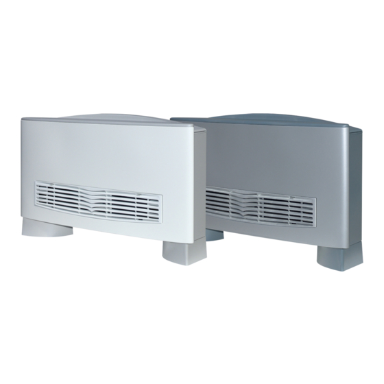
Desideriamo complimentarci con Voi per l'acquisto del ventilconvettore OMNIA HL_N Aermec. Realizzato con materiali di qualità superiore, nel rigoroso rispetto delle normative di sicurezza, "OMNIA HL_N" è di facile utilizzo e vi accompagnerà a lungo nell'uso. La serie OMNIA HL N è disponibile in due versioni cromatiche, la lettera “M” identifica solo la finitura cromatica con involucro grigio metallizato, le prestazioni e le funzioni sono identiche alle versioni con mobile bianco. -
Seite 6: Informazioni Importanti
INFORMAZIONI IMPORTANTI ATTENZIONE: I ventilconvettori trostatiche non può né raggiungere, presente nell'aria andrà a sporcare OMNIA sono concepiti per fun- né danneggiare le parti sensibili. le superfici della batteria. zionare in ambienti interni. Se si effettuano misurazioni sull’unità È NORMALE è... -
Seite 7: Manutenzione
Servizi - Pulizia del filtro precaricato elet- nella pulizia della batteria, delle Assistenza Aermec oppure da sog- trostaticamente, frequenza quin- coclee smontabili, delle alette del getti in possesso dei requisiti tec- dicinale o settimanale in caso... -
Seite 8: Funzioni Del Pannello Comandi
FUNZIONI DEL PANNELLO COMANDI La ventilazione è consentita solo con l’aletta aperta, è necessario aprirla manualmente. La chiusura dell’aletta provoca lo spegnimento della ventilazione. Per accedere al pannello comandi sollevare lo sportello di protezione. Chiudendo l’aletta del ventilconvet- tore master la scheda del termostato elettronico e gli altri ventilconvettori della rete continuno a funzionare. -
Seite 9: Uso
Accensione - Per avviare il ventilconvettore ruotare la manopola e scegliere una velocità di ventilazione. AUTO - Per spegnere il ventilconvettore ruotare la manopola fino alla posizione Il ventilconvettore è spento. Nella condizione di spento il termostato continua a funzionare. Qualora la temperatura ambiente scenda sotto i 7°C e le condizioni di impianto lo consentano, il termostato attiverà... -
Seite 10: Visualizzazioni Luminose Per L'utente (Configurazione Standard)
VISUALIZZAZIONI LUMINOSE PER L’UTENTE (CONFIGURAZIONE STANDARD) Il LED D indica la richiesta di ventilazione: BIANCA - (Acceso) Le condizioni ambientali richiedono il funzionamento del ventilatore (quando il selettore di velocità è in posizione AUTO, V1, V2, V3). AUTO - (Spento) Le condizioni ambientali non richiedono il funzionamento del ventilconvettore oppure il selettore è... -
Seite 11: Funzionamento
FUNZIONAMENTO Il ventilconvettore OMNIA HL_N concen- e le coclee dei ventilatori ispezionabili cità di ventilazione. tra elevate caratteristiche tecnologiche (eseguibile solo da personale specializ- Le impostazioni fatte sul pannello coman- e funzionali che ne fanno il mezzo idea- zato) consentono di eseguire una pulizia di possono essere trasmesse (senza le di climatizzazione per ogni ambiente. -
Seite 12: Logiche Di Regolazione Della Valvola
ne AUTO. La velocità del ventilatore è valvola è sfasata rispetto alla ventila- to al contatto Microswitch posto sulle gestita dal termostato in funzione delle zione. alette di mandata. Con alette chiuse il condizioni ambientali e della configura- ventilconvettore è in stato di spento •... -
Seite 13: Descrizione Dell'unità
DESCRIZIONE DELL’UNITÀ SCOPO DELL'UNITÀ Il ventilconvettore è un terminale per il trattamento dell’aria di un ambiente sia nella stagione invernale sia in quella estiva. Versioni Omnia HL_N e OMNIA HL_NM Ventilconvettore con mobile per installazione universale, dotato di termostato elettronico multifunzione può essere installato come unità... -
Seite 14: Fattori Di Correzione Nel Funzionamento Con Acqua Glicolata
FAT T O R I D I C O R R E Z I O N E N E L F U N Z I O N A M E N T O C O N A C Q U A G L I C O L ATA Legenda: Perdite di carico Portata... -
Seite 15: Componenti Principali
COMPONENTI PRINCIPALI 1 Pannello di comando (HL N) 7 Motore ventilatore 2 Scheda elettronica 8 Ventilatore 3 Mobile di copertura 9 Bacinella 4 Zoccoli (accessorio serie ZH) 10 Batteria di scambio termico 5 Struttura portante 11 Testata con alette orientabili 6 Filtro aria OMNIA HL_N DESCRIZIONE DEI COMPONENTI... -
Seite 16: Installazione
FILTRO ARIA PRECARICATO ELETTROSTATICAMENTE = Filtro serie HL Aermec = Filtro standard per ventilconvettori 0 , 7 2 , 0 0 , 3 0 , 5 1 , 0 Diametro particelle [µm] INSTALLAZIONE ATTENZIONE: I ventilconvettori elettrici si richiedono le verifiche... -
Seite 17: Installazione Dell'unità
INSTALLAZIONE DELL’UNITÀ - Togliere il mantello svitando le viti. scatola applicata alla fiancata, (vedi - Nella installazione a parete, si capitolo “IMPOSTAZIONI DIP-SWITCH”). mantenga una distanza minima - Eseguire tutti i collegamenti. dal pavimento di 80 mm. In caso di - Rimontare l’involucro. -
Seite 18: Collegamenti Idraulici
COLLEGAMENTI E’ necessario che le condutture dell’acqua, dello scarico condensa e il circuito elettrico siano già stati previsti. COLLEGAMENTI IDRAULICI - Effettuare i collegamenti idraulici. La posizione e il diametro degli per evitare gocciolamenti durante il Per facilitare lo sfiato dell’aria dalla attacchi idraulici sono riportati nei dati funzionamento in raffreddamento. -
Seite 19: Impostazioni Di Rete
COLLEGAMENTI ALLA SCHEDA ELETTRONICA Legenda dei collegamenti: L - N = Alimentazione elettrica SP = Non presente MS = Microswitch 230 Vac - 50 Hz Connettore tipo edge SW = Sonda acqua Morsetti a vite Pannello Comandi - TTL = Seriale Ingresso analogico Sezione minima cavo = 0,5 mm Connettore tipo faston... - Seite 20 - Rimontare la griglia di aspirazione all’u- sostituzione con uno nuovo dopo 2 nità; inserire prima i ganci inferiori nell’in- anni (disponibile come ricambio presso volucro poi inserire i ganci superiori. i centri assistenza Aermec). • Caratteristiche • Manutenzione Classe 2 (UL 900).
-
Seite 21: Contents
Congratulations on your purchase of the Aermec OMNIA HL_N fan coil. Made with materials of superior quality in strict compliance with safety regulations, "OMNIA HL_N" is easy to use and will have a long life. The OMNIA HL N series is available in two chromatic versions, the letter “M” identifies only the chromatic finish with metallic gray casing, performance and functions are identical to the version with white casing. -
Seite 22: Important Information
IMPORTANT INFORMATION IMPORTANT: OMNIA fan coils body. To do this, just touch an off unpleasant smells due to the are designed for indoor use. earthed metal object. Only use accumulation of substances pre- earthed measuring instruments. sent in the air of the room (clean the IMPORTANT: the fan coil is con- filter more often, especially if the nected to power supply and... -
Seite 23: Maintenance
Extraordinary maintenance can only type. removable volute, the fan fins, the be performed by Aermec After- - Cleaning the electrostatically pre- basin and all the parts in contact Sales Services or by people with charged filter, every two weeks with the treated air. -
Seite 24: Control Panel Functions
CONTROL PANEL FUNCTIONS Ventilation is only allowed with the fin open; it must be manually opened. The closure of the fin causes ventila- tion to switch off. To access the control panel, lift the protection flap. Closing the master fan coil fin, the electronic thermostat card and the other fan coils in the network will carry on working. -
Seite 25: Use
Starting - To start up the fan coil, turn the knob and choose a ventilation speed. - To switch off the fan coil, turn the knob to the position AUTO The fan coil is switched off. In the OFF condition, the thermostat carries on working. If the room temperature falls below 7°C, and the system conditions allow it, the thermostat will activate ventilation (anti-freeze function). -
Seite 26: Indicator Lights For The User (Standard Configuration)
INDICATOR LIGHTS FOR THE USER (STANDARD CONFIGURATION) LED D indicates a ventilation request: WHITE - (ON) The ambient conditions require the use of the fan (when the speed selector is on AUTO, V1, V2, V3). - (OFF) The ambient conditions do not require the use of the fan, or AUTO the selector is in the OFF (standby) position, or the fin is closed - (slow flashing) Operation mode managed by the centralised... -
Seite 27: Operation
OPERATION The OMNIA HL_N fan coil concentrates (by specifically trained personnel), interfaces) to a network with up to 5 fan hi-tech and highly functional featur- essential for installations in venues sub- coils, all equipped with their own elec- esthat make it the ideal means of cli- ject to crowding or in those with special tronic card. - Seite 28 on AUTO. The fan maintains the speed temperature will be measured by the carry on working. relating to one of the three predeter- master probe along. In this case, ventila- • Emergency operation mined steps, depending on the differ- tion is always enabled on the slave fan In the event of a faulty probe, the elec- ence between room temperature and coil.
-
Seite 29: Description Of The Unit
DESCRIPTION OF THE UNIT AIM OF THE UNIT The fan coil is a room air treatment terminal unit for both winter and summer operation. Versions Omnia HL_N and OMNIA HL_NM A fan coil with cabinet, for universal installation and fitted with a multifunction electronic thermostat. It can be installed as an autonomous unit or within a network: it can, in fact, manage a network of a further 5 fan coils*. -
Seite 30: Correction Factors When Operating Us In Glycol Water
C O R R E C T I O N F A C T O R S W H E N O P E R A T I N G G L Y C O L W A T E R Key: Pressure drops Air flow rate... -
Seite 31: Main Components
MAIN COMPONENTS 1 Control panel (HL N) 7 Fan motor 2 Electronic card 8 Fan 3 Cabinet 9 Basin 4 Feet (accessory ZH) 10 Heat exchange coil 5 Load-bearing structure 11 Head with adjustable fins 6 Air filter OMNIA HL_N DESCRIPTION OF COMPONENTS CONTROL PANEL CABINET... -
Seite 32: Installation
ELECTROSTATICALLY PRECHARGED AIR FILTER = Aermec HL range filter = Standard filter for fan coils 0 , 7 2 , 0 0 , 3 0 , 5 1 , 0 Particle diameter [µm] INSTALLATION - Measurement of the electrical system... -
Seite 33: Unit Installation
UNIT INSTALLATION - Loosen the screws to remove the the box on the side (see “DIP-SWITCH housing. SETTINGS”). - With wall-mounted units, keep a - Make all the connections. minimum clearance of 80mm from the - Reassemble the casing. floor. With floor-standing units on feet, - Make sure the fan coil is working refer to the instructions supplied with properly. -
Seite 34: Water Connections
CONNECTIONS The water, condensate discharge and electrical circuit ducts must be provided for. WATER CONNECTIONS - Make the water connections. To help Te s t t h e s e a l o n t h e wate r water connections are shown in the the bleeding of air from the coil, you connections. -
Seite 35: Network Settings
CONNECTIONS TO THE ELECTRONIC CARD Connections key: L - N = Power supply SA = SA Air probe MS = Microswitch 230 Vac - 50 Hz Analogue input Edge-type connector Screw clamps Removable-type connector Control panel - TTL = Local serial TTL Minimum cable section = 0.5mm Maximum cable length = 3 m Removable-type connector... -
Seite 36: Dip-Switch Settings
- Reattach the ventilation grille to the years with a new one is recommended unit. First insert the lower hooks of the (available as a spare part from Aermec cover, and then insert the upper hooks. After Sales centres). •... -
Seite 37: Table Des Matières
Veuillez accepter nos compliments les plus sincères pour avoir acheté le ventilo-convecteur OMNIA HL_N Aermec. Réalisé avec des matériaux de première qualité, dans le plus grand respect des normes de sécurité, "OMNIA HL_N" est facile à utiliser et destiné à durer longtemps. -
Seite 38: Informations Importantes
INFORMATIONS IMPORTANTES AT TENTION: Les ventilo - atteindre, et donc détruire, les par- salir la surface de la batterie. convecteurs OMNIA ont été ties sensibles. IL EST NORMAL conçus pour fonctionner à l'inté- Si on effectue des mesures sur Pendant le fonctionnement en mode rieur. -
Seite 39: Entretien
être fait plus fréquemment. être effectué que par les services type. Ces opérations comportent le après vente Aermec ou bien par Nettoyage du filtre préchargé élec- nettoyage de la batterie, des vis des personnes possédant les trostatiquement, fréquence tous sans fin démontables, des ailettes... -
Seite 40: Fonctions Du Panneau De Commande
FONCTIONS DU PANNEAU DE COMMANDE La ventilation n'est permise qu'avec l'ailette ouverte, il faut l'ouvrir manuellement. La fermeture de l'ailette provoque l'extinction de la ventilation. Pour accéder au panneau de com- mande, soulever la porte de protec- tion. En fermant l'ailette du ventilocon- vecteur maître, la carte du thermos- tat électronique et les autres ventilo- convecteurs du réseau continuent à... -
Seite 41: Utilisation
UTILISATION Mise en marche - Pour démarrer le ventilo-convecteur, tourner la molette et choisir une vitesse de ventilation. AUTO - Pour éteindre le ventilo-convecteur, tourner la molette jusqu'à la position Le ventilo-convecteur est éteint. Même lorsque le ventilo-convecteur est éteint, le thermostat continue à fonctionner. -
Seite 42: Affichages Lumineux Pou R L'utilisateur (Réglage Ordinaire)
AFFICHAGES LUMINEUX POU R L'UTILISATEUR (RÉGLAGE ORDINAIRE) La DEL D indique la demande de ventilation : BLANC - (allumée) Les conditions environnementales exigent le fonctionnement du ventilateur (lorsque le sélecteur de vitesse est en position AUTO, V1, V2, V3). AUTO - (Éteint) Les conditions environnementales n'exigent pas le fonctionnement du ventilo-convecteur, ou le sélecteur est en position OFF (veille), ou bien l'ailette est fermée. -
Seite 43: Fonctionnement
FONCTIONNEMENT Le ventilo-convecteur OMNIA HL_N réu- sans fin des ventilateurs susceptibles l'autre pour allumer/éteindre l'unité et nit des caractéristiques technologiques d'inspection (opération qui ne peut être pour régler la vitesse de ventilation. et fonctionnelles élevées qui en font le effectuée que par du personnel spécia- Les réglages réalisés sur le panneau de moyen de climatisation idéal pour tous lisé) permet d'effectuer un nettoyage... -
Seite 44: Fonctionnement D'urgence
• Ventilation tures et fermetures de la vanne, en faisant de ventilo-convecteurs, seul le contact circuler de l'eau chaude dans le ventilo- extérieur du ventilo-convecteur maître est La ventilation à trois vitesses peut être convecteur, sur demande du thermostat, la activé. -
Seite 45: Description De L'unité
DESCRIPTION DE L'UNITÉ OBJET DE L'UNITÉ Le ventilo-convecteur est un terminal pour le traitement de l’air d’un milieu, tant en hiver qu’en été. Versions Omnia HL_N et OMNIA HL_NM Ventilo-convecteur avec carosserie pour installation universelle, doté de thermostat électronique multifonction, qui peut être installé... -
Seite 46: Facteurs De Correction Dans Le Fonctionnement Avec Eau Glycolée
FAC T E U R S D E CO R R E C T I O N D A N S L E F O N C T I O N N E M E N T AV E C E AU G LYCO L É E Légende: Pertes de charge Débit... -
Seite 47: Composants Principaux
COMPOSANTS PRINCIPAUX 1 Panneau de commande (HL N) 7 Moteur du ventilateur 2 Carte électronique 8 Ventilateur 3 Meuble de couverture 9 Bac 4 Socles (accessoire de série ZH) 10 Batterie d'échange thermique 5 Structure portante 11 Tête avec ailettes orientables 6 Filtre à... -
Seite 48: Instalation
FILTRE À AIR PRÉCHARGÉ ÉLECTROSTATIQUEMENT = Filtre de série HL Aermec = Filtre ordinaire pour ventilo-convecteurs 0 , 7 2 , 0 0 , 3 0 , 5 1 , 0 Diamètre des particules [µm] INSTALATION AT T E N T I O N : L e s ve n t i l o - suivantes sont requises pour les les échangeurs de chaleur en cuivre-... -
Seite 49: Installation De L'unité
INSTALLATION DE L'UNITÉ - Dévisser les vis de la couverture puis commutateurs DIP dans la fenêtre l'enlever. respective du boîtier situé sur le - En cas d'installation murale, il faut flanc (voir le chapitre “RÉGLAGES DES maintenir une distance minimale au COMMUTATEURS DIP”). -
Seite 50: Raccords Hydrauliques
RACCORDEMENTS Il est nécessaire que les conduites d'eau, d'évacuation des condensats ainsi que du circuit électrique aient déjà été prévues. RACCORDS HYDRAULIQUES - Effectuer les raccords hydrauliques. La position et le diamètre des raccords disponible comme accessoire, pour Pour faciliter la purge de l'air hydrauliques sont reportés dans les éviter des écoulements pendant de la batterie, il est conseillé... -
Seite 51: Réglages Du Réseau
BRANCHEMENTS À LA CARTE ÉLECTRONIQUE Légende des branchements: L - N = Alimentation électrique FUSE = Fusible de protection MS = Microrupteur 230 Vac ~ 50 Hz Fusible de 2 A retardé Connecteur encartable Bornes à vis SA = SA sonde d'air Panneau de Commande - TTL = Série Section minimale du câble = 0,5 mm Entrée analogique... - Seite 52 • Caractéristiques neuf tous les 2 ans (pièce de rechange Classe 2 (UL 900). disponible dans les centres d'assistance Facile à extraire, il est fourni dans Aermec). un emballage scellé qui ne doit IHLNLJ 2204 - 6887212_02...
-
Seite 53: Indice
Wir möchten Sie zum Kauf des Gebläsekonvektors OMNIA HL_N von Aermec beglückwünschen. Aus Materialien von hoher Qualität und unter genauer Einhaltung der Sicherheitsbestimmungen hergestellt, lässt sich "OMNIA HL_N" einfach benutzen und wird Sie lange Zeit im Gebrauch begleiten. Die Baureihe OMNIA HL N wird in zwei Farben angeboten. Der Buchstabe “M” kennzeichnet das Farbfinish mit grau metallisiertem Gehäuse. -
Seite 54: Wichtige Hinweise
WICHTIGE HINWEISE A C H T U N G : D i e O M N I A elektrostatischen Entladungen die demzufolge Unwohlsein auslösen. Gebläsekonvektoren sind für den empfindlichen Teile nicht erreichen WÄHREND DES BETRIEBS Betrieb in Innenräumen konzipiert. oder beschädigen. Lassen Sie während des Betriebs Wenn Messungen am Gerät durch- A C H T U N G :... -
Seite 55: Embalaje 54
Kundendienststelle R ä u m e n m i t h o h e n - Reinigung des elektrostatisch gela- Aermec bz w. von qualifizier- Sauberkeitsansprüchen kann die denen Filters (vierzehntägig ten Technikern ausgeführt wer- Reinigung auch öfter vorgenom- oder wöchentlich bei Installation... -
Seite 56: Funktionen Der Bedientafel
FUNKTIONEN DER BEDIENTAFEL Die Lüftung ist nur bei offener Lamelle zulässig, die manuell zu öffnen ist. Schließt man die Lamelle, schaltet sich die Lüftung aus. Für den Zugriff auf die Bedientafel die Schutzklappe anheben. Schließt man die Lamelle des Master-Gebläsekonvektors blei- ben die Platine des elektronischen Thermostats und die anderen in Netzschaltung verbundenen... -
Seite 57: Einschalten
GEBRAUCH Einschalten - Zum Anstarten des Gebläsekonvektors den Griff drehen und eine Gebläsedrehzahl auswählen. AUTO - Zum Ausschalten des Gebläsekonvektors den Griff bis in die Stellung drehen . Der Gebläsekonvektor ist ausgeschaltet. Im ausgeschalteten Zustand bleibt der Thermostat weiterhin in Betrieb. Sollte die Raumtemperatur unter 7°C absinken und der Zustand der Anlage es zulassen, aktiviert der Thermostat die Lüftung (Frostschutzfunktion). -
Seite 58: Leuchtanzeigen Für Den Benutzer (Standardkonfiguration)
LEUCHTANZEIGEN FÜR DEN BENUTZER (STANDARDKONFIGURATION) LED D zeigt die Lüftungsansteuerung an: WEISS - (Eingeschaltet) Die Raumbedingungen er fordern den Gebläsebetrieb (bei Stellung des Drehzahlwahlschalters auf AUTO, V1, V2, V3). AUTO - (Ausgeschaltet) Die Raumbedingungen erfordern nicht den Betrieb des Gebläsekonvektors oder der Wahlschalter steht auf OFF (Stand-by) oder die Lamelle ist geschlossen - (Langsames Blinken) Betriebsart, die von der Zentralsteuerung gesteuert wird. -
Seite 59: Funcionamiento
BETRIEBSWEISE Der Gebläsekonvektor OMNIA HL_N Durch die Möglichkeit, die Wanne und Ausschalten und zur Einstellung der ist ein Konzentrat aus erstklassigen die Ventilatorschaufeln abzunehmen Gebläsedrehzahl. technologischen und funktionellen (nur durch Fachpersonal ausführbar), Die Einstellungen, die an der Bedientafel Eigenschaften, wodurch er sich für ist auch eine sorgfältige Reinigung vorgenommen werden, können (ohne die Klimatisierung eines jeden Raums... -
Seite 60: Heizbetrieb, Das Ventil Wird So
Einstellungen des Thermostats: Wasser temperatur fühler arbeiten, der Gebläsekonvektor vollständig aus- - 3 - s t u f i g e r T h e r m o s t a t . M i t wenn dieser nicht vorhanden (oder geschaltet. -
Seite 61: Beschreibung Der Einheit
BESCHREIBUNG DER EINHEIT ZWECK DES GERÄTS Der Gebläsekonvektor ist eine Endeinheit für die Raumluftbehandlung sowohl für den Winter- als auch den Sommerbetrieb. Versionen Omnia HL_N und OMNIA HL_NM Gebläsekonvektor mit Verkleidung für universellen Einbau, ausgestattet mit elektronischem Multifunktions-Thermostat, installierbar als eigenständiges Gerät oder in Netzschaltung mit bis zu 5 anderen Gebläsekonvektoren*. * Die in Netzschaltung verbundenen Gebläsekonvektoren müssen voreingestellte Modelle sein oder mit entsprechenden Zubehörteilen ausgestattet sein. -
Seite 62: Factores De Corrección En El Funcionamiento Con Agua Glicolada
KO R R E K T U R FA K TO R E N F Ü R D E N B E T R I E B M I T E I N E R WA S S E R - G LYKO L - M I S C H U N G Legende: Druckverluste Durchfluß... -
Seite 63: Hauptkomponenten
HAUPTKOMPONENTEN 1 Bedientafel (HL N) 7 Motor des Ventilators 2 Platine 8 Ventilator 3 Verkleidung 9 Wanne 4 Sockel (Zubehörteil Serie ZH) 10 Wärmetauscher 5 Trägerstruktur 11 Kopfteil mit schwenkbaren Lamellen 6 Luftfilter OMNIA HL_N BESCHREIBUNG DER KOMPONENTEN BEDIENTAFEL oberen Teil des Wärmetauschers. Der Halterungen stoßgedämmt ist. -
Seite 64: Anlageninstallationen Installiert
ELEKTRISCH AUFGELADENER LUFTFILTER = Filter der Serie HL Aermec = Standardfilter für Gebläsekonvektoren 0 , 7 2 , 0 0 , 3 0 , 5 1 , 0 Partikeldurchmesser [µm] INSTALLATION A C H T U N G : D i e O M N I A Besonders für die elektrischen... -
Seite 65: Installation Der Einheit
INSTALLATION DER EINHEIT - den Mantel durch Ausschrauben der - Zur Änderung der Einstellungen des Schrauben entfernen. elektronischen Thermostats an den - b e i Wa n d i n s t a l l a t i o n i s t e i n e Dip-Schaltern über die entsprechende B o d e n h ö... -
Seite 66: Anschlüsse Zum Kondensatablauf
ANSCHLÜSSE Die Wasserleitungen, der Kondensatablauf und die elektrischen Leitungen müssen bereits vorbereitet sein. WASSERANSCHLÜSSE - Nehmen Sie die Hydraulikanschlüsse Gerätebetrieb keineswegs. Kondensatwanne zu installieren, um v o r. U m d a s E n t l ü f t e n d e s Po s i t i o n u n d Q u e r s c h n i t t e d e r zu vermeiden, dass während des Austauschers zu vereinfachen, ist... -
Seite 67: Anschlüsse An Die Elektronikkarte
ANSCHLÜSSE AN DIE ELEKTRONIKKARTE Legende der Anschlüsse: L - N = Stromversorgung SA = SA Lufttemperaturfühler MS = Mikroschalter 230 Vac - 50 Hz Analoger Eingang Edge-Verbinder Schraubklemmen Ausziehbarer Stecker Bedientafel - TTL = Seriell Lokal TTL Kleinster Kabelquerschnitt = 0,5 mm Maximale Kabellänge = 3 m Ausziehbarer Stecker Größter Kabelquerschnitt = 2,0 mm... -
Seite 68: Einstellungen Dip-Schalter
1 2 3 4 5 6 7 8 1 2 3 4 5 6 7 8 INSTALLATION DES ELEKTROSTATISCH AUFGELADENEN LUFTFILTERS • Installation • Eigenschaften Kundendienststellen der Fa. Aermec - Das Luftansauggitter von der Einheit erhältlich). Klasse 2 (UL 900). abmontieren. Die oberen Haken des •... -
Seite 69: Inhaltsverzeichnis
Deseamos felicitarles por la compra del fan coil OMNIA HL_N Aermec. Realizado con materiales de calidad superior y mostrando un riguroso respeto a las normativas de seguridad, "OMNIA HL_N" se caracteriza por su fácil manejo y les acompañará durante mucho tiempo en su uso. -
Seite 70: Informaciones Importantes
INFORMACIONES IMPORTANTES ATENCIÓN: Los fan coils OMNIA ES NORMAL ticas no puede alcanzar o dañar las han sido diseñados para fun- partes sensibles. Durante el funcionamiento en frío cionar en ambientes interiores. Si se realizan mediciones en la uni- puede salir vapor de agua por el dad se deben, antes de realizar canal de envío del fan coil. -
Seite 71: Problemas Y Soluciones
Servicios de tes de todo tipo. zarse con mayor frecuencia; con- Asistencia Aermec, o por alguien - Limpieza del filtro precargado con siste en la limpieza de la batería, que reúna los requisitos técnico- electricidad estática, frecuencia... -
Seite 72: Funktionen Der Bedientafel
FUNCIONES DEL TABLERO DE MANDOS La ventilación es posible sólo con la aleta abierta, es necesario abrir- la manualmente. El cierre de la aleta da lugar al apaga- do de la ventilación. Para acceder al tablero de mandos, levantar la tapa de protección. Si se cierra la aleta del fan coil mas- ter, la tarjeta del termostato electró- nico y los demás fan coils de la red... -
Seite 73: Gebrauch
Encendido - Para encender el fan coil, gire el mando y seleccione una velocidad de ventilación. - Para apagar el fan coil, gire el mando hasta la posición AUTO El fan coil está apagado. En la condición de apagado, el termostato continúa funcionando. Cuando la temperatura ambiente descienda por debajo de los 7°C y las condiciones de la instalación lo permitan, el termostato activará... -
Seite 74: Leuchtanzeigen Für Den Benutzer (Standardkonfiguration)
INDICACIONES LUMINOSAS PARA EL USUARIO (CONFIGURACIÓN ESTÁNDAR ) El LED D indica la solicitud de ventilación: BLANCO - (Encendido) Las condiciones ambientales requieren el funcionamiento del ventilador (cuando el selector de velocidad está en posición AUTO, V1, V2, V3). AUTO - (Apagado) Las condiciones ambientales no requieren el funcionamiento del fan coil o el selector está... -
Seite 75: Betriebsweise
FUNCIONAMIENTO El fan coil OMNIA HL_N reúne elevadas experto) es posible limpiar profunda- mitir (sin interfaces) a una red de hasta características tecnológicas y funciona- mente también las partes internas, con- 5 fan coils equipados con tarjeta elec- les que lo convierten en el medio ideal dición necesaria para aquellas instala- trónica específica. - Seite 76 de la configuración del fan coil. biador. del fan coil master se detiene la ven- Configuraciones del termostato: El fan coil puede funcionar sin sonda de tilación pero la tarjeta del termostato - Termostato de 3 niveles. Con el selec- agua.
-
Seite 77: Descripción De La Unidad
DESCRIPCIÓN DE LA UNIDAD OBJETIVO DE LA UNIDAD El fan coil es un terminal para el tratamiento del aire de un ambiente tanto en invierno como en verano. Versiones Omnia HL_N y OMNIA HL_NM Fan coil con mueble para la instalación universal, equipado con termostato electrónico multifunción, que puede instalarse como unidad autónoma o en red, de hecho puede controlar una red de 5 fan coils*. -
Seite 78: Korrekturfaktoren Für Den Betrieb Mit Einer Wasser-Glykol-Mischung
FA C TO R E S D E CO R R E CC I Ó N E N E L F U N C I O N A M I E N TO CO N A G UA G L I CO L A D A Leyenda: Pérdidas de carga Caudal... -
Seite 79: Componentes Principales
COMPONENTES PRINCIPALES 1 Tablero de mando (HL N) 7 Motor ventilador 2 Tarjeta electrónica 8 Ventilador 3 Mueble de cobertura 9 Cubeta 4 Zócalos (accesorio de serie ZH) 10 Batería de intercambio térmico 5 Estructura portante 11 Parte superior con aletas orientables 6 Filtro del aire OMNIA HL_N DESCRIPCIÓN DE LOS COMPONENTES... -
Seite 80: Ejemplos De Instalación
FILTRO DE AIRE PRECARGADO ELECTROSTÁTICAMENTE = Filtro serie HL Aermec = Filtro estándar para fan coils 0 , 7 2 , 0 0 , 3 0 , 5 1 , 0 Diámetro de las partículas [µm] INSTALACIÓN ATENCIÓN: Los fan coils OMNIA eléctricas, es necesario comprobar :... -
Seite 81: Instalación De La Unidad
INSTALACIÓN DE LA UNIDAD - Quitar la cubierta desenroscando los correspondiente de la caja aplicada tornillos. al lateral , ( véase el capítulo - En la instalación en pared, disponer “CONFIGURACIÓN DIP-SWITCH”). una distancia mínima de 80 mm del - Realice todas las conexiones. suelo. -
Seite 82: Conexiones Hidráulicas
CONEXIONES Es necesario que las tuberías del agua, de la descarga del agua de condensación y el circuito eléctrico hayan sido previstas. Conexiones hidráulicas - Realice las conexiones hidráulicas. La posición y el diámetro de las durante la operación en frío. Para facilitar la ventilación de R e a l i c e p r u e b a... - Seite 83 CONEXIONES A LA TARJETA ELECTRÓNICA Leyenda de las conexiones: L - N = Alimentación eléctrica SA = SA Sonda aire MS = Microswitch 230 Vac - 50 Hz Entrada analógica Conector tipo edge Bornes de tornillo Conector tipo extraíble Tablero de mandos - TTL = Serial Local TTL Sección mínima del cable = 0,5 mm Longitud máxima del cable = 3 m Conector tipo extraíble...
- Seite 84 • Instalación Características dos años (disponible como recambio -Desmonte la rejilla de aspiración de la en los centros de asistencia Aermec). Clase 2 (UL 900). unidad; con la punta de una herramienta • De fácil extracción, se distribuye en Mantenimiento haga palanca en los ganchos superiores una confección sellada, que debe...
-
Seite 85: Dimensioni • Dimensions • Abmessungen • Dimensiones [Mm]
DIMENSIONI • DIMENSIONS • ABMESSUNGEN • DIMENSIONES [mm] 1 0 0 Mod Omnia HL 11 HL 16 HL 26 HL 36 Larghezza • Width • Largeur • Breite • Longitud 1200 Altezza • Height • Hauteur • Höhe • Altura Profondità... -
Seite 86: Dimensioni • Dimensions • Abmessungen • Dimensiones [Mm]
DIMENSIONI • DIMENSIONS • ABMESSUNGEN • DIMENSIONES [mm] 1 Testata con alette orientabili 2 Mobile di copertura 3 Struttura portante 4 Zoccolo ZH 5 Spazio per i collegamenti 1 Head with adjustable fins 2 Cabinet 3 Load-bearing structure 4 Foot ZH 5 Space for connections 1 Tête avec ailettes orientables 2 Carosserie de protection... -
Seite 87: Schemi Elettrici • Wiring Diagrams • Schemas Electriques • Elektrische Schaltpläne • Esquemas Electricos
SCHEMI ELETTRICI • WIRING DIAGRAMS • SCHEMAS ELECTRIQUES • ELEKTRISCHE SCHALTPLÄNE • ESQUEMAS ELECTRICOS LEGENDA • KEY • LEGENDE • LEGENDE • LEYENDA = Interruttore generale • Master switch • Interrupteur général • Hauptschalter • Interruptor general = Morsettiera • Control board • Bornier • Klemmleiste • Caja de conexiones = Microinterruttore •... -
Seite 88: Schemi Elettrici • Wiring Diagrams • Schemas Electriques • Elektrische Schaltpläne • Esquemas Electricos
SCHEMI ELETTRICI • WIRING DIAGRAMS • SCHEMAS ELECTRIQUES • ELEKTRISCHE SCHALTPLÄNE • ESQUEMAS ELECTRICOS LEGENDA • KEY • LEGENDE • LEGENDE • LEYENDA = Arancio = Orange = orange = Orange = Naranja = Bianco = White = blanc = Weiß = Blanco = Blu = Blue... - Seite 89 ATTENZIONE! Questo apparecchio è previsto per essere fissato alla parete o la soffitto. Qualora venga installato diversamente dovrà obbligatoriamente essere impiegato il pannello di coperturea fornito come accessorio . (norme EN 60335-1) WARNING! This application is designed for wall or ceiling installation.For other types of installation the beck panel accessory must be used. (standard 60335-1) ATTENTION! Cet appareil est conçu pour installation à...
-
Seite 90: Servizio Assistenza Tecnica (Italia)
Tel. 0438 450269 - Fax 0438 450283 EMILIA ROMAGNA 21020 Brebbia VA Tel. 0372 471637 - Fax 0372 471637 centrotecnico@ctmenegazzo.com Tel. 0332 971073 - Fax 0332982221 aerservice@aermec.it BOLOGNA info@cielleclima.it TRIESTE - GORIZIA MANTOVA LA CLIMATIZZAZIONE TRIESTE srl (tutta la gamma esclusi split system) - Seite 91 Tel. 06 232488500 MOLISE 26022 Castelverde (CR) satmarchionni@yahoo.it MARCHE CAMPOBASSO - ISERNIA Tel. 0372 471637 - Fax 0372 471637 aerservice@aermec.it VITERBO PETRONGOLO ARIAN ANCONA - PESARO - URBINO AIR FRIGO srl Via Torremontanara, 46 REGGIO EMILIA AERSAT snc di Marchetti S. & Sisti F.
- Seite 92 AERMEC S.p.A. si riserva la facoltà di apportare in qualsiasi momento tutte le modifiche ritenute necessarie per il miglioramento del prodotto. Les données mentionnées dans ce manuel ne constituent aucun engagement de notre part. Aermec S.p.A. se réserve le droit de modifier à tous moments les données considérées nécessaires à...