Hacker HST-350 Betriebsanleitung
Brushless dc controller

Verwandte Anleitungen für Hacker HST-350


Inhaltszusammenfassung für Hacker HST-350
- Seite 1 Betriebsanleitung Brushless DC Controller HST-350 Hacker Motor GmbH Schinderstraßl 32 84030 Ergolding Hacker Motor GmbH Telefon: +49 871-953628-35 Schinderstraßl 32 Fax: +49 871-953628-29 D-84030 Ergolding E-Mail: his@hacker-motor.com Rev1.3 Web: www.hacker-industrial-solutions.com...
-
Seite 2: Sprache Der Betriebsanleitung
If you need the manual in a different language than the one available to you, please contact us. English instructions start on page 33. Hacker Motor GmbH Schinderstraßl 32 D-84030 Ergolding Phone: +49-871-953628-35 Fax: +49-871-953628-29 Internet: www.hacker-industrial-solutions.com E-mail: his@hacker-motor.com Seite 2 von 62 Brushless DC Controller HST-350 Orginalbetriebsanleitung Rev1.3... -
Seite 3: Inhaltsverzeichnis
Belegung Sensorschnittstelle....................10 Anschlussschema........................13 Motorsteuerung........................16 Leistungssteuerung / Betriebsmodi..................17 Kommunikations-Schnittstellen.....................18 Betrieb des Reglers mit der GUI und Einstellungen in der Software........19 5. Service und Support........................31 Rechtliche Bestimmungen.....................31 Haftungsausschluss .........................31 CE-Konformitätserklärung ......................32 Kontaktinformationen.........................32 Seite 3 von 62 Brushless DC Controller HST-350 Orginalbetriebsanleitung Rev1.3... -
Seite 4: Wichtige Grundlegende Informationen
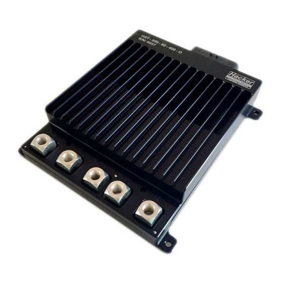
Etiketts auf dem Controller. Diese 8-stellige Zahl soll- te mit 25xxxxxx beginnen. Allgemeine Beschreibung des Produkts Der HST-350 V2.5 ist ein high Performance brushless Motor Controller für den industriellen Ein- satz. Er ist in der Lage (brushless) bürstenlose DC Motore (BLDC) mit Blockkommutierung zu betreiben. -
Seite 5: Sicherheit
Zur bestimmungsgemäßen Verwendung gehört auch die Einhaltung aller Vorgaben und Grenzen, die in der Betriebsanleitung erläutert werden. Als nicht bestimmungsgemäße Verwendung im Sinne einer vorhersehbaren Fehlanwen- dung gilt • Betrieb jenseits der vorgeschriebenen technischen Spezifikationen Seite 5 von 62 Brushless DC Controller HST-350 Orginalbetriebsanleitung Rev1.3... -
Seite 6: Nutzungsart
WARNUNG Der Bediener ist erst im Umgang mit dem Produkt befugt, wenn die Erst-Inbetrieb- nahme erfolgt ist und alle erforderlichen Schutzanforderungen der entsprechend an- wendbaren Produktnormen und Richtlinien erfüllt sind. Seite 6 von 62 Brushless DC Controller HST-350 Orginalbetriebsanleitung Rev1.3... -
Seite 7: Sicherheitshinweise
HINWEIS EMV Störungen Störung von EMV-störempfindlichen umliegenden Bauteilen. EMV-störungsempfindliche Bauteile sollten in möglichst großer Entfernung zum Reg- ler und Motor verbaut werden. Ist dies aufgrund von bauraumtechnischen Gründen nicht möglich, so sind diese durch geeignete Maßnahmen abzuschirmen. Seite 7 von 62 Brushless DC Controller HST-350 Orginalbetriebsanleitung Rev1.3... -
Seite 8: Technische Daten
Technische Daten Technische Daten Räumliche Grenzen Erforderlicher Montageraum: · ca. 185x183x41mm. · Gesamtgewicht ca. 1400g Seite 8 von 62 Brushless DC Controller HST-350 Orginalbetriebsanleitung Rev1.3... -
Seite 9: Schnittstellen
Überspannung erzeugen die den Regler beschädigt oder zerstört. Beachten sie darum unbedingt beim Betrieb an einem Netzteil eine ausreichend dimensionierte Kondensatorbatterie in die Versorgungsleitungen zu integrieren die die überschüssige Energie aufnehmen kann. Seite 9 von 62 Brushless DC Controller HST-350 Orginalbetriebsanleitung Rev1.3... -
Seite 10: Montage Und Inbetriebnahme
Achten Sie auf die passenden Querschnitte zur Leistung. Es ist vorgesehen die Phasen- und Akkukabel mit M10-Linsenkopfschrauben (Anzugsdrehmoment 17Nm) zu befestigen. Bringen Sie dazu passende Ring- oder Rohrkabelschuhe an den Kabeln an. Belegung Sensorschnittstelle 35 pole socket ESC of HST-350 Signal description Signal Function Description... - Seite 11 Internal function signal ground* ISO GND isolated GND *geht nicht für Std.-GND fan-control output (load) Power supply 5V of +5V_Track2 +5V power supply 10 pole 6 / red Hall sensors (pin24-26,28-30) Seite 11 von 62 Brushless DC Controller HST-350 Orginalbetriebsanleitung Rev1.3...
- Seite 12 Montage und Inbetriebnahme Seite 12 von 62 Brushless DC Controller HST-350 Orginalbetriebsanleitung Rev1.3...
-
Seite 13: Anschlussschema
Montage und Inbetriebnahme Anschlussschema Sensorkabel (optional) Seite 13 von 62 Brushless DC Controller HST-350 Orginalbetriebsanleitung Rev1.3... - Seite 14 Strom kann dies zerstören und lebensbedrohliche Schäden verursa- chen. Beispiel (blaue Linien stellen speziellen Kabelbaum für die Anwendung ohne Relais dar): Poti Kl. 15 Dual CAN V5-Display Sensorkabel (optional) Seite 14 von 62 Brushless DC Controller HST-350 Orginalbetriebsanleitung Rev1.3...
- Seite 15 Montage und Inbetriebnahme Sensor Adapter- kabel HST-350 #10108147 Sensoran- schluss Seite 15 von 62 Brushless DC Controller HST-350 Orginalbetriebsanleitung Rev1.3...
-
Seite 16: Motorsteuerung
Je nach Anwendung, kann eine Funktion weggelassen werden (z.B. 34 – Lüfter), dafür kann die gewünsch- te Funktion eingepinnt werden (z.B. Akku-Temp.). Motorsteuerung Der HST-350 unterstützt verschiedene Modi zur Motoransteuerung. Den gewünschten Modus können Sie über die GUI (grafische Bedienoberfläche) einstellen. Blockkommutierung (BLDC) Im BLDC Mode wird der Motor über 2 Phasen angetrieben, die dritte Phase dient zur Ermittlung des Kom- mutierungszeitpunktes. -
Seite 17: Leistungssteuerung / Betriebsmodi
: td = 1,0 ms Pulslänge (-100% = umgekehrt) Mittlere Einstellung : td = 1,5 ms Pulsbreite (0% = Neutralstellung, Motor aus) Maximalwert : td = 2,0 ms Pulslänge (+ 100% = vorwärts) Seite 17 von 62 Brushless DC Controller HST-350 Orginalbetriebsanleitung Rev1.3... -
Seite 18: Kommunikations-Schnittstellen
5.3 ADC (U ) Analogeingang Statt eines digitalen Signals kann auch eine analoge Spannung zwischen 0...5V an den jeweiligen Anschluss an- gelegt werden um Setpoint und Bremse (Rekuperation) zu steuern. Seite 18 von 62 Brushless DC Controller HST-350 Orginalbetriebsanleitung Rev1.3... -
Seite 19: Betrieb Des Reglers Mit Der Gui Und Einstellungen In Der Software
Ein Windows Rechner mit installierter GUI Das Installationspaket bekommen Sie von uns nach Aufforderung. • Einen USB to CAN Adapter (Best. #10107621) (Treiber kann über his@hacker-motor.com angefragt werden) • Der Controller muss wie oben gezeigt angeschlossen und mit Spannung versorgt sein. • Der Motor sollte sich für den Test frei drehen können Verbinden Sie die CAN-Bus-Leitungen des 12-poligen Molex-Steckers: •... - Seite 20 Feld „Received Data“ das Datenprotokoll sichtbar sein und sich permanent aktualisieren drücken Sie dann auf [scan motors]; Sie sollten dann im Fenster „devices in normal mode“ das Gerät 69 als Motor Nr 1 sehen • Der Controller hat nun die Verbindung zur Programmieroberfläche erfolgreich hergestellt. • Der Controller ist nun betriebsbereit und kann mit einer neuen Firmware geflasht oder parametriert werden Seite 20 von 62 Brushless DC Controller HST-350 Orginalbetriebsanleitung Rev1.3...
- Seite 21 Bis Version 24 -> Firmware Version 39 Ab Version 25 -> Firmware Version 40 Bis HW-Version 24: Motor 1: 69er, Motor 2: 32er-Prozessor Ab HW-Version 25: Motor 1: 69er, Motor 2: 35er-Prozessor Seite 21 von 62 Brushless DC Controller HST-350 Orginalbetriebsanleitung Rev1.3...
- Seite 22 Dann drücken Sie den Button [Boot] wie im nächsten Bild zu sehen; der Button wird blau und das System quittiert mit der Statusmeldung „Boot mode“. • Drücken Sie nun den Button [Flash], damit wird die Software auf den Controller über- tragen. Seite 22 von 62 Brushless DC Controller HST-350 Orginalbetriebsanleitung Rev1.3...
- Seite 23 Wechseln Sie ins Register „EEPROM“ am rechten Rand des Bootloaders Öffnen Sie den Pfad zum neuen EEPROM Wählen Sie ein passendes EEPROM aus und bestätigen Sie; die Daten werden sofort zum Controller übertragen Der Controller quittiert mit der Meldung „read EEPROM S4 ok“ Seite 23 von 62 Brushless DC Controller HST-350 Orginalbetriebsanleitung Rev1.3...
- Seite 24 Es werden Ihnen im Software-Paket verschiede Vorlagen zu häufig benutzen Anwendungen angeboten: Ee_gen für Generator Anwendungen Eep für Standardanwendungen mit Hallsensoren Eep_Hybrid für Anwendungen die einen Hybridbetrieb benötigen (mit/ ohne Sensorik) Eep_Sensor_Less für Anwendungen die ohne Hall-Sensoren auskommen Innerhalb dieser Verzeichnisse wiederum finden Sie weiter detaillierte Vorlagen. Seite 24 von 62 Brushless DC Controller HST-350 Orginalbetriebsanleitung Rev1.3...
- Seite 25 Dieses EEPROM können Sie sich nun auf Ihren PC abspeichern mit dem Button [Save File to PC]. Sichern Sie sich regelmäßig Ihre verschiedenen Versionen ab, damit Sie immer wieder darauf zu greifen können, wenn Sie diese benötigen. Seite 25 von 62 Brushless DC Controller HST-350 Orginalbetriebsanleitung Rev1.3...
- Seite 26 Dazu vor dem Herausziehen des CAN-Adapters oben/links den Button [Release] drücken. Nun muss der Regler neu gestartet werden, trennen Sie ihn dazu ca. 10 Sekunden von der Span- nungsversorgung und schließen Sie ihn dann wieder an. Für weitere Unterstützung wenden Sie sich an his@hacker-motor.com HINWEIS Ändern von Parametern Das Ändern der Parameter erfordert ein fundiertes Fachwissen.
- Seite 27 Im Screenshot erkennen Sie, dass wir über CAN steuern und Current Control als Betriebsmodus ausgewählt haben. Im nächsten Schritt schalten wir den Controller ein; drücken Sie dazu den Button [ON] Seite 27 von 62 Brushless DC Controller HST-350 Orginalbetriebsanleitung Rev1.3...
- Seite 28 Wir empfehlen Ihnen dringend, die Antriebseinheit vor dem Einbau in die Applikation, auf einem separaten Prüfstand in Betrieb zu nehmen und auf korrekte Funktion zu überprüfen. Bedenken Sie bitte, dass Sie mit hohen elektrischen Strömen und großen, mechani- schen Kräften arbeiten. Seite 28 von 62 Brushless DC Controller HST-350 Orginalbetriebsanleitung Rev1.3...
- Seite 29 Geben Sie einen Wert innerhalb der vorgegebenen Limits (hier im Beispiel: 0 - 350 / -350 - 0) ein und bestätigen Sie dann mit [Set]. Der Schieberegler springt an die entsprechende Stelle. Seite 29 von 62 Brushless DC Controller HST-350 Orginalbetriebsanleitung Rev1.3...
- Seite 30 Spannung, Strom, Stromverbrauch, Laufrichtung und Werte der angeschlossenen Sensoren (Temperatu- ren, Drehzahl) verschaffen Ihnen ein Bild über die Effizienz und Funktion Ihres Antriebs. Wenn Sie Werte ändern, vergleichen Sie die ausgegebenen Parameter nach der Änderung. So können Sie den Antrieb Ihren Vorstellungen entsprechend optimieren oder an eine neue Umgebung anpassen. Seite 30 von 62 Brushless DC Controller HST-350 Orginalbetriebsanleitung Rev1.3...
-
Seite 31: Service Und Support
Einsatz des Produktes und dessen Wartung nicht möglich ist, kann von der Fa. Hacker Motor GmbH keinerlei Haftung für Verluste, Schäden oder Kosten gewährt werden. Jeglicher Anspruch auf Schadensersatz, der sich durch den Betrieb, den Ausfall bzw. Fehlfunk- tionen ergeben kann, oder in irgendeiner Weise damit zusammenhängt wird abgelehnt. -
Seite 32: Ce-Konformitätserklärung
Einsteinstr. 9 93055 Regensburg GERMANY Phone: +49 941 28092013 E-Mail: info@hersi.biz Registergericht: Amtsgericht Regensburg HRA 7014 Kontaktinformationen Der Vertrieb des HST-350 Controllers sowie des Zubehörs erfolgt über die Hacker Motor GmbH Geschäftsführer: Rainer Hacker Schinderstraßl 32 D-84030 Ergolding Telefon: +49-871-953628-35...