
Verwandte Anleitungen für IFM Electronic efector 160 LK10


Inhaltszusammenfassung für IFM Electronic efector 160 LK10
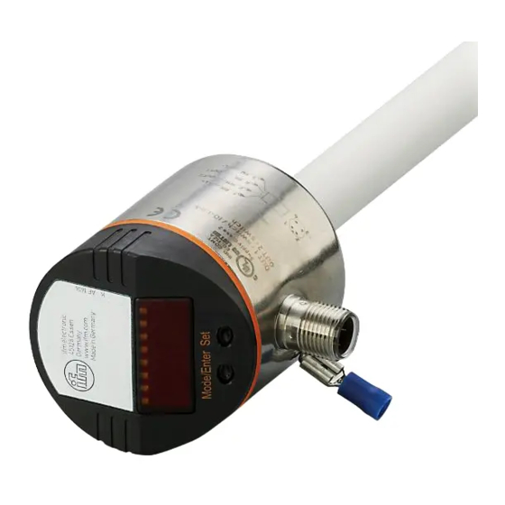
- Seite 1 Bedienungsanleitung Operating instructions Notice pour utilisateurs Elektronischer Füllstandsensor Electronic level sensor Capteur de niveau électronique LK10...
-
Seite 2: Inhaltsverzeichnis
Inhalt Bedien- und Anzeigeelemente ....... 4 Bestimmungsgemäße Verwendung ......5 Funktionsbeschreibung . -
Seite 3: Menü-Übersicht
Menü-Übersicht... -
Seite 4: Bedien- Und Anzeigeelemente
Bedien- und Anzeigeelemente Leuchtende LED = eingestellte Anzeigeeinheit: 2 x LED grün - LED 1 = Anzeige des Füllstands in cm. - LED 2 = Anzeige des Füllstands in inch. Anzeige des Schaltzustands; leuchtet, wenn der jeweilige Ausgang durchgeschaltet ist. 2 x LED gelb - LED 1 = OUT1 (frei konfigurierbarer Ausgang). -
Seite 5: Bestimmungsgemäße Verwendung
Bestimmungsgemäße Verwendung Einsatzbereich Der Füllstandsensor LK10 wurde speziell für die Bedürfnisse des Werkzeugmaschinenbaus konzipiert. Er ist insbesondere geeignet für die Überwachung von Kühlschmieremulsionen (auch verschmutzt) sowie von Kühl- und Hydraulikölen. Beschränkung des Einsatzbereichs • Das Gerät ist nicht geeignet für stark leitende und anhaftende Medien, Granulate, Schüttgüter, Säuren und Laugen;... -
Seite 6: Funktionsübersicht
Funktionsübersicht • Das Gerät ist in unterschiedlichen Behältergrößen einsetzbar und flexibel montierbar. Befestigungsvorrichtungen können sich auch im aktiven Messbereich befinden. Beachten Sie bitte die Montagehinweise (→ Seite 7). • Zur Anpassung an verschiedene Medien lassen sich die Empfindlichkeit und der Erfassungsmodus des Gerätes einstellen. Damit ist eine sichere Erfassung auch von Medien mit sehr niedri- gem DK-Wert (wie z. -
Seite 7: Montage
Montage LK1022 LK1023 LK1024 inch inch inch L (Stablänge) 26,4 10,4 47,2 18,6 72,8 28,7 M (Montagebereich) 14,2 • Befestigen Sie Montageelemente innerhalb des Bereichs M. • Montageelemente müssen oberhalb des Messsegments OP und in einem Mindestabstand zu OP befestigt werden (siehe Wert y, gemessen zur Mitte des Segments). -
Seite 8: Markieren Der Einbauhöhe
• Bei Einbau in Kunststoffrohren / Kunststoffbehältern muss der (Rohr-) / Innendurchmesser mindestens 12 cm (4,8 inch) betragen. • Bei Einbau in Metallrohren muss der Rohr-Innendurchmesser (d) mindestens folgenden Wert haben: MEDI = CLW1 MEDI = CLW2, OIL1 MEDI = OIL2 inch inch inch... -
Seite 9: Elektrischer Anschluss
Elektrischer Anschluss Das Gerät darf nur von einer Elektrofachkraft installiert werden. Befolgen Sie die nationalen und internationalen Vorschriften zur Errichtung elektrotechnischer Anlagen. Spannungsversorgung nach EN50178, SELV, PELV. Schalten Sie die Anlage spannungsfrei; schließen Sie das Gerät folgendermaßen an: Pin / Belegung Adernfarben bei ifm-Kabeldosen braun OUT2 (Schaltausgang 2) -
Seite 10: Programmieren
Programmieren Drücken Sie die Taste Mode/Enter, bis der gewünschte Parameter Mode/Enter Set im Display erscheint. Drücken Sie die Taste Set und halten Sie sie gedrückt. Mode/Enter Set Der aktuelle Parameterwert wird 5 s lang blinkend angezeigt, danach wird er erhöht* (schrittweise durch Einzeldruck oder kontinuierlich durch Festhalten der Taste). - Seite 11 Führen Sie zur Programmierung die folgenden Schritte in der angegebenen Reihenfolge durch. Schritt Programmiervorgang Parameter Anzeigeeinheit auswählen Stellen Sie die gewünschte Anzeigeeinheit ein: cm / inch. Stellen Sie die Anzeigeeinheit ein, bevor Sie die Werte für SPx, rPx, OP oder den Offset (OFS) festlegen. Dadurch ver- meiden Sie Rundungsfehler bei der internen Umrechnung auf die jeweils andere Einheit und erhalten exakt die gewünschten Werte.
- Seite 12 Schritt Programmiervorgang Parameter Überfüllsicherung Mit Parameter OP legen Sie die Ansprechhöhe der Über- füllsicherung fest (OP = overflow protection). Der einge- stellte Wert bezieht sich auf die Mitte des gewählten Messsegments. Typischerweise spricht OP bereits an bei Erreichen des OP-Segments. Ansprechzeit: Typisch 450 ms, maximal 720 ms.
- Seite 13 Schritt Programmiervorgang Parameter Einstellen der Schaltparameter SP1: Schaltpunkt 1 = oberer Grenzwert, bei dem Schaltausgang OUT1 seinen Schaltzustand ändert. rP1: Rückschaltpunkt 1 = unterer Grenzwert, bei dem Schaltausgang OUT1 seinen Schaltzustand ändert. OU1: Schaltfunktion für Schaltausgang OUT1. Es sind 4 Einstellungen wählbar: Hysterese- (H..) oder Fensterfunktion (F..);...
- Seite 14 Schritt Programmiervorgang Parameter Abgleichvorgang • Taste Mode/Enter drücken, bis cOP im Display erscheint. • Taste Set drücken und festhalten. erscheint blin- kend im Display. Taste loslassen, wenn Anzeige nicht mehr blinkt. • Ist der Abgleich erfolgreich, wird rdy angezeigt. Tastendruck führt zurück zum Menü. Während des Abgleichs überprüft das Gerät die Einbausituation durch Auswertung des Messsignals, das vom OP-Element erzeugt wird.
-
Seite 15: Einstellbereiche Für Ofs
Einstellbereiche für OFS LK1022 LK1023 LK1024 inch inch inch Einstellbereich 0...78 0...30,6 0...57 0...22,4 0...186 0...73 Schrittweite Einstellwerte für OP LK1022 LK1023 LK1024 inch inch inch 13,9 16,3 18,8 10,9 10,6 21,2 12,3 11,8 23,6 13,8 13,0 26,1 10,3 15,2 14,3 28,5 11,2... - Seite 16 Hysteresefunktion (Hno, Hnc): Hysterese hält Schaltzustand des Ausgangs sta- bil, wenn der Prozesswert um den Sollwert schwankt. Hysterese steigendem Prozesswert schaltet Ausgang Erreichen des Schaltpunkts (SPx / OP*). Fällt der Prozesswert wie- der ab, schaltet der Ausgang erst dann zurück, wenn Rückschaltpunkt rPx unterschrit- L = Füllstand...
-
Seite 17: Inbetriebnahme / Betrieb
Inbetriebnahme / Betrieb Prüfen nach Montage, elektrischem Anschluss Programmierung, ob das Gerät sicher funktioniert. Betriebs- und Fehleranzeigen: Initialisierung nach dem Einschalten. XX.X Anzeige des Füllstands. Füllstand unterhalb des aktiven Bereichs. OP (Überfüllsicherung) ist erreicht. FULL “FULL” und die Anzeige des aktuellen Füllstands wechseln im XX.X Sekundentakt (= Warnanzeige Überfüllung). -
Seite 18: Ausgangsverhalten In Verschiedenen Betriebszuständen
Einstellung der Parameter ablesen: • Kurzer Druck auf die Taste “Mode/Enter” blättert durch die Parameter. • Kurzer Druck auf die Taste “Set” zeigt jeweils 15 s lang den zugehörigen Parameterwert ohne ihn zu verändern. Ausgangsverhalten in verschiedenen Betriebszuständen OUT1 OUT2 Initialisierung OP-Abgleich nicht durchgeführt OP-Abgleich durchgeführt... -
Seite 19: Technische Daten
Technische Daten Betriebsspannung [V] ......18 ... 30 DC Strombelastbarkeit [mA] ........200 Kurzschlussschutz, getaktet, Verpolungssicher / Überlastfest Spannungsabfall [V] . -
Seite 20: Applikationen
Applikationen Hydraulik-Aggregat Mindestfüllstand-Überwachung mit Vorwarnung und Alarm Schaltausgang 1: Vorwarnung Geringfügig über rP1 (um Wellenbewegungen auszublenden) Soll-Füllstand unterschritten → Vorwarnung, Nachfüllen starten Hysteresefunktion, Öffner (Hnc) Schaltausgang 2: Alarm Min-Wert wieder erreicht → Alarm zurückgesetzt Min-Wert unterschritten → Alarm Hysteresefunktion, Schließer (Hno) Vorwarnung Alarm Anzeigewert... - Seite 21 Applikationen Hebeanlage Behälter entleeren mit Überfüllsicherung Schaltausgang 1: Regelung Behälter entleeren Oberer Normalwert überschritten → Tauchpumpe EIN Unterer Normalwert erreicht → Tauchpumpe AUS Hysteresefunktion, Schließer (Hno) Schaltausgang 2: Überfüllsicherung Maximalwert überschritten → Alarm Geringfügig unter SP2 (um Wellenbewegungen auszublenden) Hysteresefunktion, Öffner (Hnc) Überfüll- Entleeren sicherung...
- Seite 22 Applikationen Vorlage- bzw. Druckerhöhungsbehälter Gutbereich-Überwachung (Alarm) und Regelung des Füllstands Schaltausgang 1: Nachfüllen Oberer Sollwert erreicht → Nachfüllen beenden Unterer Sollwert unterschritten → Nachfüllen starten Hysteresefunktion, Öffner (Hnc) Schaltausgang 2: Sicherheitfunktion Min-Max Max-Wert überschritten → Alarm Min-Wert unterschritten → Alarm Fensterfunktion, Schließer (Fno) Min- Max-...
-
Seite 23: Maßzeichnung
Maßzeichnung LK1022 LK1023 LK1024 inch inch inch L (Stablänge) 26,4 10,4 47,2 18,6 72,8 28,7 A (aktiver Bereich) 19,5 39,0 15,4 58,5 23,0 (inaktiver Bereich 1) 10,2 (inaktiver Bereich 2) 4-stellige alphanumerische Anzeige Status-LEDs Programmiertasten Gehäuseanschluss (Flachstecker 6,3 mm nach DIN 46244) -
Seite 24: Safety Instructions
Contents Controls and indicating elements ......25 Function and features ........26 Functional overview . -
Seite 25: Menu Structure
Menu structure... -
Seite 26: Controls And Indicating Elements
Controls and indicating elements Lighting LED = set display unit: 2 x LED green - LED 1 = level in cm. - LED 2 = level in inch. Switching status indication; lights if the respective output is switched. 2 x LED yellow - LED 1 = OUT1 (freely configurable output). -
Seite 27: Function And Features
Function and features Applications The level sensor LK10 was specially designed to meet the require- ments of machine tool building. It is specially suitable for monitoring coolant emulsions (also dirty) as well as cutting and hydraulic oils. Restriction of the application area •... - Seite 28 Functional overview • The unit can be installed in tanks of different sizes. Mounting ele- ments may also be placed in the active measurement zone. Please adhere to the mounting instructions (→ page 29). • The sensitivity and the mode of detection of the unit can be set in order to adjust to different media.
-
Seite 29: Mounting
Mounting LK1022 LK1023 LK1024 inch inch inch L (probe length) 26.4 10.4 47.2 18.6 72.8 28.7 M (mounting zone) 14.2 • Fasten mounting elements within zone M. • Mounting elements must be fixed above the measuring segment OP and at a minimum distance to OP (see value y, measured to the middle of the segment). -
Seite 30: Mounting Accessories
• For mounting in plastic pipes / plastic tanks the inside (pipe) diameter must be min. 12 cm (4.8 inchs). • For mounting in metal pipes the inside pipe diameter must be at least: MEDI = CLW1 MEDI = CLW2, OIL1 MEDI = OIL2 inch inch... -
Seite 31: Electrical Connection
Electrical connection The unit must be connected by a suitably qualified electrician. The national and international regulations for the installation of electrical equipment must be observed. Voltage supply according to EN50178, SELV, PELV. Disconnect power before connecting the unit as follows: Pin / connection core colours of ifm sockets brown... -
Seite 32: Programming
Programming Press the Mode/Enter button several times until the respective Mode/Enter Set parameter is displayed. Press the Set button and keep it pressed. The current parameter Mode/Enter Set value flashes for 5 s, then the value is increased* (incremental by pressing briefly or scrolling by holding pressed). - Seite 33 For programming carry out the following steps in the indicated order. Step Programming Parameter Selection of the display unit Set the required display unit: cm / inch. Select the display unit before setting values for the para- meters (SPx, rPx, OP). This avoids rounding errors gener- ated internally during the conversion of the units and enables exact setting of the values.
- Seite 34 Step Programming Parameter Overflow protection With the parameter OP the response level of the overflow protection is defined (OP = overflow protection). The set value refers to the middle of the selected measuring seg- ment. Typically, OP reacts when the OP segment is reached.
- Seite 35 Step Programming Parameter Setting of the switching parameters SP1: set point 1 = upper limit value at which the switching output OUT1 changes its switching status. rP1: reset point 1 = lower limit value at which the switching output OUT1 changes its switching status. OU1: switching function for the switching output OUT1.
- Seite 36 Step Programming Parameter Adjustment operation: • Press the Mode/Enter button until cOP is displayed. • Press the Set button and keep it pressed. is indi- cated (flashing). Release the button when the display stops flashing. • If adjustment is successful, rdy is indicated. Return to the menu by pressing the Mode/Enter button.
- Seite 37 Setting range for OFS LK1022 LK1023 LK1024 inch inch inch Setting range 0...78 0...30.6 0...57 0...22.4 0...186 0...73 in steps of Setting values for OP LK1022 LK1023 LK1024 inch inch inch 13.9 16.3 18.8 10.9 10.6 21.2 12.3 11.8 23.6 13.8 13.0 26.1...
- Seite 38 Hysteresis function (Hno, Hnc): The hysteresis keeps the switch- ing state of the output stable if the level of the medium varies about the preset value. hysteresis With the level rising, the output switches when the set point has been reached (SPx / OP*). With the level falling, the output does not switch back until the level falls below the reset point rPx or...
-
Seite 39: Installation And Set-Up / Operation
Installation and set-up / Operation After mounting, wiring and programming check whether the unit operates correctly. Operating and fault indication: Initialisation after power on. XX.X Level indication. Level below the active zone. FULL OP (overflow protection) is reached. "FULL" and the indication of the current level alternate every XX.X second (= warning overflow). -
Seite 40: Output Response In Different Operating States
Read the set parameter values: • The parameter names are scrolled with each pressing of the "Mode/Enter" button. • When the "Set" button is pressed briefly, the corresponding para- meter value is displayed for 15 s. Output response in different operating states OUT1 OUT2 Initialisation... -
Seite 41: Technical Data
Technical data Operating voltage [V] ......18 ... 30 DC Current rating [mA] ........200 Short-circuit protection;... -
Seite 42: Applications
Applications Hydraulic tank Minimum level monitoring with prewarning and alarm Switching output 1: prewarning slightly above rP1 (to suppress wave movements) below preset level → prewarning, start refilling hysteresis function, normally closed (Hnc) Switching output 2: alarm min. value reached again → alarm reset below min. - Seite 43 Applications Pumping station Empty the tank with overflow protection Switching output 1: control to empty tank upper value exceeded → submersible pump ON lower value reached → submersible pump OFF hysteresis function, normally open (Hno) Switching output 2: overflow protection maximum value exceeded →...
- Seite 44 Applications Storage tank Monitoring of the acceptable range (alarm) and level control Switching output 1: refilling upper preset value reached → finish refilling below lower preset value → start refilling hysteresis function, normally closed (Hnc) Switching output 2: safety function min - max max.
-
Seite 45: Scale Drawing
Scale drawing LK1022 LK1023 LK1024 inch inch inch L = probe length 26.4 10.4 47.2 18.6 72.8 28.7 A = active zone 19.5 39.0 15.4 58.5 23.0 (inactive zone 1) 10.2 (inactive zone 2) 4-digit alphanumeric display LEDs Programming buttons Housing connection (flat-pin connector 6.3 mm folowing DIN 46244) - Seite 46 Contenue Eléments de service et d'indication ......48 Fonctionnement et caractéristiques ......49 Aperçu des fonctions .
-
Seite 47: Structure Du Menu
Structure du menu... -
Seite 48: Eléments De Service Et D'indication
Eléments de service et d'indication LED allumée = unité sélectionnée : 2 x LED verte - LED 1 = niveau en cm. - LED 2 = niveau en inch. Indication de l'état de commutation, LED allumée si la sortie correspondante est commutée. 2 x LED jaune - LED 1 = OUT1 (sortie à... -
Seite 49: Fonctionnement Et Caractéristiques
Fonctionnement et caractéristiques Application Le capteur de niveau LK10 a été conçu notamment pour satisfaire aux exigences des applications en machines-outils. Il est particulièrement approprié pour contrôler des liquides d'arrosage et de lubrification (émulsions même chargées) ainsi que des huiles de coupe et hydrau- liques. -
Seite 50: Aperçu Des Fonctions
Aperçu des fonctions • L'appareil peut être utilisé et monté indifféremment dans des cuves de tailles différentes. Les éléments de fixation peuvent également se trouver dans la zone de mesure active. Veuillez respecter les remarques sur le montage (→ page 51). •... -
Seite 51: Montage
Montage LK1022 LK1023 LK1024 inch inch inch L (longueur de la sonde) 26,4 10,4 47,2 18,6 72,8 28,7 M (zone de montage) 14,2 • Fixer des éléments de montage dans la zone M1. • Les éléments de montage doivent être fixés au-dessus du segment de mesure OP et à... - Seite 52 • En cas de montage dans des tuyaux plastiques / cuves plastiques, le diamètre intérieur (du tuyau) doit être min. 12 cm (4,8 inch). • En cas de montage dans des tuyaux métalliques, le diamètre intérieur (d) du tuyau doit être au moins de : MEDI = CLW1 MEDI = CLW2, OIL1 MEDI = OIL2...
-
Seite 53: Raccordement Électrique
Raccordement électrique L'appareil doit être monté par un électricien. Les règlements nationaux et internationaux relatifs à l'installation de matériel électrique doivent être respectés. Alimentation selon EN50178, TBTS, TBTP. Mettre l'installation hors tension avant de raccorder l'appareil comme suit : Couleurs des fils conducteurs des Broche / raccordement connecteurs femelles ifm : brun... -
Seite 54: Programmation
Programmation Appuyer sur le bouton Mode/Enter plusieurs fois jusqu'à ce que le Mode/Enter Set paramètre désiré soit affiché. Appuyer sur le bouton Set et le maintenir appuyé. Mode/Enter Set La valeur de paramètre actuelle clignote pendant 5 s, après la valeur est incrémentée* (pas à... - Seite 55 Programmation Paramètre Sélection de l'unité d'affichage Choisir l'unité d'affichage : cm / inch. Choisir l'unité d'affichage avant de régler les valeurs pour les paramètres (SPx, rPx, OP). Cela évitera les erreurs d'arrondi générées en interne lors de la conversion des unités et permettra de régler des valeurs exactes.
- Seite 56 Programmation Paramètre Protection contre le débordement Avec le paramètre OP vous définissez le niveau de répon- se de la protection contre le débordement (OP = overflow protection). La valeur réglée se réfère au milieu du seg- ment de mesure sélectionné. Typiquement, OP réagit déjà lorsque le segment OP est atteint.
- Seite 57 Programmation Paramètre Réglage des paramètres de commutation SP1: point de consigne haut 1 = valeur limite maximale à laquelle la sortie de commutation OUT1 change son état de commutation. rP1: point de consigne bas 1 = valeur limite minimale à laquelle la sor- tie de commutation OUT1 change son état de commutation.
- Seite 58 Programmation Paramètre Opération de réglage : • , jusqu'à ce que cOP Appuyer sur le bouton Mode/Enter soit affiché. • Appuyer sur le bouton Set et le maintenir appuyé. clignote. Relâcher le bouton quand L’indication l'affichage ne clignote plus. • En cas de réglage réussi, rdy est indiqué. Retourner au menu en appuyant sur le bouton Mode/Enter.
- Seite 59 Plages de réglage pour OFS LK1022 LK1023 LK1024 inch inch inch Plage de réglage 0...78 0...30,6 0...57 0...22,4 0...186 0...73 en pas de Valeurs de réglage pour OP LK1022 LK1023 LK1024 inch inch inch 13,9 16,3 18,8 10,9 10,6 21,2 12,3 11,8 23,6...
- Seite 60 Fonction hystérésis (Hno, Hnc) : L'hystérésis garantit un état de commutation stable de la sortie en cas de fluctuations du niveau du fluide autour de la valeur hystérésis présélectionnée. Si le niveau augmente, la sortie commute lorsque la consigne haute est atteinte (SPx / OP*). Si le niveau diminue de nouveau, la sortie ne commute que lorsque le niveau est en-dessous de rPx...
-
Seite 61: Mise En Service / Fonctionnement
Mise en service / Fonctionnement Après le montage, le raccordement électrique et la programmation, vérifier le bon fonctionnement de l'appareil. Indication de fonctionnement et de défauts : Initialisation après la mise sous tension. XX.X Indication du niveau. Niveau en-dessous de la zone active. FULL OP (protection contre le débordement) atteint. - Seite 62 Lecture des valeurs de paramètres réglées : • Si le bouton-poussoir "Mode / Enter" est appuyé brièvement, les paramètres sont parcourus. • Si le bouton-poussoir "Set" est appuyé brièvement, la valeur de paramètre correspondante est indiquée pendant env. 15 s. Comportement de la sortie en différents modes de fonctionnement OUT1...
-
Seite 63: Données Techniques
Données techniques Tension d'alimentation [V] ......18 ... 30 DC Courant de sortie [mA] ........200 Protection : courts-circuits, inversion de polarité, surcharges Chute de tension [V] . -
Seite 64: Applications
Applications Cuve hydraulique Surveillance du niveau minimal avec pré-alarme et alarme Sortie de commutation 1: pré-alarme faiblement supérieur à rP1 (pour supprimer les mouvements de vagues) au-dessous du niveau présélectionné → pré-alarme, commencer le remplissage fonction hystérésis, normalement fermé (Hnc) Sortie de commutation 2: alarme valeur minimale atteinte de nouveau →... - Seite 65 Applications Système de pompage Vider une cuve avec protection contre le débordement Sortie de commutation 1: régulation vider une cuve valeur normale supérieure dépassée → pompe submersible EN MARCHE valeur normale inférieure atteinte → pompe submersible ARRET fonction hystérésis, normalement ouvert (Hno) Sortie de commutation 2: protection contre le débordement valeur maximale dépassée →...
- Seite 66 Applications Cuve de stockage Surveillance de la plage acceptable (alarme) et régulation du niveau Sortie de commuation 1: remplissage valeur préselectionnée supérieure atteinte → terminer le remplissage au-dessous de la valeur préselectionnée inférieure → commencer le remplissage fonction hystérésis, normalement fermé (Hnc) Sortie de commutation 2: fonction de sécurité...
-
Seite 67: Dimensions
Dimensions LK1022 LK1023 LK1024 inch inch inch L (longueur de la sonde) 26,4 10,4 47,2 18,6 72,8 28,7 A (zone active) 19,5 39,0 15,4 58,5 23,0 (zone non active 1) 10,2 (zone non active 2) Visualisation alphanumérique à 4 digits LEDs Boutons-poussoir Raccord au boîtier (connecteur plat 6,3 mm selon...