Werbung
Verfügbare Sprachen
Verfügbare Sprachen
Quicklinks
Analogue Temperature Transmitters
Model T91.10 / T91.20
Typ T91.10
1. Safety instructions
When mounting, commissioning and operating these
transmitters, it is important to observe the respective
national safety precautions and regulations in effect
(e.g. VDE 100). Nonobservance of the applicable regulations may cause
severe injury to persons or damage to equipment. Only staff with suitable
qualifications should work with these transmitters. Before commissioning,
check the instrument's suitability for the intended application. In particular, it
is important to observe the ambient and operating limits as specified in the
WIKA data sheet, TE 91.01.
2.
Mounting
Model T91.10 head mounting transmitters are designed to be mounted on
a measuring insert in a DIN Form B connection head. Model T91.20 head
mounting transmitters are designed to be mounted on a measuring insert
in a Form J connection head. The connecting wires of the measuring insert
must be approx. 50 mm long and insulated.
3. Maintenance
The temperature transmitters described here are maintenance free! The
electronics do not incorporate any components which could be repaired
or replaced. Depending upon operating conditions, it may be advisable to
check the calibration of the transmitter yearly.
4. Electrical connections
These transmitters have an internal galvanic connection between the sensor
input and analogue output. No external connection should be made (for
example, by earthing) between the connected temperature sensor and
analogue output! For this reason it is best to use isolated thermocouples. For
flying leads we recommend using crimped connector sleeves. To connect
a thermocouple: Make sure that the thermocouple is connected with the
correct polarity. If the cable between the thermocouple and the transmitter
must be extended, only use the appropriate thermal or compensating cable
for the connected thermocouple type.
Operating Instructions
Typ T91.20
4.1 Pt100 input
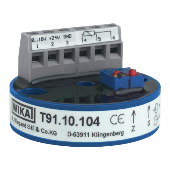
Model T91.10.104
Pt100 in 2- or 3-wire connection.
For a 2-wire connection the resistance of the wires affects the
measurement results. Therefore this circuit should only be selected if the
wires are short, or accuracy requirements are low. If using a 2-wire connec-
tion, always connect a jumper between input terminals 5 and 6. Transmitter
output signal: 0 ... 10 V / 3-wire design
230 VAC
24 VDC
Zero
Model T91.10.424
Pt100 in 2-wire connection
Transmitter output signal: 0 ... 10 V / 3-wire design
230 VAC
24 VDC
Zero
Model T91.20.143
Pt100 in 2-wire connection
Transmitter output signal: 4 ... 20 mA / 2-wire design
Last
(PLC, PC)
Span
230 VAC
24 VDC
4.2 Sensoreingang Thermoelement
Model T91.10.102
The positive lead of the thermocouple is connected to terminal TC+ on the
transmitter and the negative lead to terminal TC-. Transmitter output signal:
0 ... 10 V / 3-wire design
230 VAC
24 VDC
Zero
Last
(PLC, PC)
Pt100
Span
Last
(PLC, PC)
Pt100
Span
Zero
Loop
Pt100
Last
(PLC, PC)
Thermocouple
Span
Werbung

Verwandte Anleitungen für WIKA T91.10


Inhaltszusammenfassung für WIKA T91.10
- Seite 1 Mounting (PLC, PC) Span Zero Model T91.10 head mounting transmitters are designed to be mounted on a measuring insert in a DIN Form B connection head. Model T91.20 head Loop Pt100 mounting transmitters are designed to be mounted on a measuring insert in a Form J connection head.
- Seite 2 (in our example 70 °C = 10 V) matches the desired value. 5) Repeat step 1 and check signal (1 V) 6) Repeat step 3 and check signal (10 V) WIKA Alexander Wiegand SE & Co. KG 5.3 Adjustment of the 4 ... 20 mA output signal Alexander-Wiegand-Straße 30 1) Set the lower value of the measurement range with the simulator, e.g.
- Seite 3 Last (SPS, PC) Spanne Nullpunkt 2. Montage Transmitter des Typs T91.10 sind vorgesehen zur Montage auf einem Loop Pt100 Messeinsatz im DIN-Anschlusskopf der Form B. Transmitter Typ T91.20 zur Montage auf einem Messeinsatz im Anschlusskopf der Form J. Die Anschlussdrähte des Messeinsatzes müssen ca. 50 mm lang und isoliert 230 VAC ausgeführt sein.
- Seite 4 Ausgang lässt sich bis etwa 0,002 V an die untere Versorgungsspan- 1) 0 V bzw. < 4 mA Fühlerkurzschluss beim Thermoelement ■ nung aussteuern (Typ T91.10.424 bis etwa 0,02 V). 2) Entspricht Raumtemperatur 3) > 10 V / > 20 mA Fühlerbruch 4.4 Anschluss der 4 ...