Herunterladen Inhalt Inhalt Diese Seite drucken
Endress+Hauser RNS 221 Bedienungsanleitung

Endress+Hauser RNS 221 Bedienungsanleitung

Messumformer speisegerät

Werbung

Verfügbare Sprachen

Verfügbare Sprachen

KA 110R/09/a3/10.03
510 02645
RNS 221
;
Messumformer Speisegerät
<
Power supply
=
Alimentation de transmetteur

Werbung

Inhaltsverzeichnis
loading

Inhaltszusammenfassung für Endress+Hauser RNS 221

  • Seite 1 RNS 221 KA 110R/09/a3/10.03 510 02645 Messumformer Speisegerät < Power supply Alimentation de transmetteur...
  • Seite 3: Inhaltsverzeichnis

    Messumformer Speisegerät Inhaltsverzeichnis Seite 1 Sicherheitshinweise ............................4 2 Funktion ................................5 3 Montage................................6 4 Verdrahtung ..............................7 5 Inbetriebnahme..............................8 6 Wartung ................................8 7 Technische Daten ............................9...
  • Seite 4: Sicherheitshinweise

    1 Sicherheitshinweise Das Gerät ist ein Speisegerät für Messaufnehmer und -umformer. Das Gerät darf nicht in explosionsgefährdeten Bereichen installiert Bestimmungsgemäße werden! Verwendung Für Schäden aus unsachgemäßem oder nicht bestimmungsgemä- ßem Gebrauch haftet der Hersteller nicht. Umbauten und Änderun- gen am Gerät dürfen nicht vorgenommen werden. Das Gerät ist für den Einsatz in industrieller Umgebung konzipiert und darf nur im eingebauten Zustand betrieben werden.
  • Seite 5: Funktion

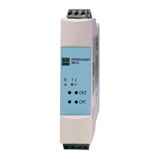
    2 Funktion Das Gerät liefert zwei von einander galvanisch getrennte Spannungen von 24 VDC. Der maximal abgegebene Strom pro Ausgang beträgt 30 mA. Die Ausgänge sind elektronisch überwacht. Die Ausgangsspan- nung ist stabilisiert auf 24 V ± 10%, bei Kurzschluss ist der Strom auf 38 mA begrenzt.
  • Seite 6: Montage

    3 Montage Das Gerät ist für die Hutschienenmontage nach EN 50 022-35 vorgese- hen. Einbauhinweise Der Einbauort muss frei von Vibrationen sein. Zulässige Umgebungstemperatur von -20...+60 °C einhalten. Gerät vor Wärmeeinwirkung schützen. Gehäuseabmessungen in mm...
  • Seite 7: Verdrahtung

    4 Verdrahtung Klemmenbelegung Klemmenbelegung Ein- und Ausgang L/L+ L für AC L+ für DC Eingangsseite Hilfsenergie N/L- N für AC L- für DC Versorgung Messumformer 1 und 2 (+) Ausgangsseite Messumformerspeisung Versorgung Messumformer 1 und 2 (-) Versorgung Messumformer 1 und 2 mit ®...
  • Seite 8: Inbetriebnahme

    Anschluss Hilfsenergie Im Spannungsbereich von 90...253 VAC muss in der Zuleitung in der Nähe des Gerätes ein als Trennvorrichtung gekenn- zeichneter Schalter sowie ein Überstrom- ˆ schutzorgan (Nennstrom 10 A) ange- bracht sein. Anschluss Ausgang 1 und 2 Bei Einschleifung des Kommunikationswi- derstandes in die Stromschleife ist der Spannungsabfall zu berücksichtigen! ®...
  • Seite 9: Technische Daten

    7 Technische Daten Ausgangskenngrößen Leerlaufspannung 24V +/- 10% Ausgangsstromkreis max. 30 mA ® Hart -Kommunikationswiderstand , intern eingebaut Kurzschlussstrom beide Kanäle sind dauerkurzschlussfest Rippel < 100 mV bei 20 mA Last Galvanische Trennung Zwischen allen Stromkreisen Hilfsenergie Spannungsversorgung 20...253 V DC/AC, 50/60 Hz Leistungsaufnahme <...
  • Seite 10 Umgebungsbedingungen (Fortsetzung) Überspannungsschutz Nach IEC 61010-1 Überspannungskategorie II Installationsseitiges ≤ Überstromorgan 10 A Konstruktiver Aufbau Bauform/Maße Gehäuse für Hutschiene nach EN 50 022-35 H: 110 mm, B: 22,5 mm, T: 112 mm Gewicht ca. 140 g Werkstoffe Gehäuse: Kunststoff PC/ABS, UL 94V0 Anschlussklemmen Netz- und Signalanschlüsse: Codierte steckbare Schraubklemmen,...
  • Seite 11 Power Supply Table of Contents Page 1 Safety instructions............................12 2 Function .................................13 3 Installation ..............................14 4 Electrical connection............................15 5 Commissioning ..............................16 6 Maintenance ..............................16 7 Technical Data ...............................17...
  • Seite 12: Safety Instructions

    q The unit is a power supply for sensors and transmitters. The unit is not 1 Safety instructions to be installed in explosion hazardous areas! Correct use q The manufacturer cannot be held responsible for damage caused by incorrect use of the unit. Changes, constructive or otherwise, must not be made to the unit.
  • Seite 13: Function

    2 Function The unit delivers two galvanically isolated voltages of 24 V DC. The maximum current supplied, per output, is 30 mA. The outputs are electronically monitored. The output voltage is stabilised to 24 V ± 10%, current is limited to 38mA on short circuit. ®...
  • Seite 14: Installation

    3 Installation The unit is meant for top hat DIN rail mounting according to EN 50 022-35. q The installtion point must be free of vibration. Installation hints q Always stay within the permitted ambient temperature range of -20...+60 °C. q Protect the unit from external heat sources.
  • Seite 15: Electrical Connection

    4 Electrical connection Terminal layout Terminal layout In and outputs L/L+ L for AC L+ for DC Input for main power N/L- N for AC L- for DC Power supply to transmitter 1 and 2 (+) Output for transmitter power supply Power supply to transmitter 1 and 2 (-) Power supply to transmitter 1 and 2 ®...
  • Seite 16: Commissioning

    Connecting main power When operating using a power source between 90...253 VAC, an isolator must be fitted within easy reach of the unit. Also an overvoltage protection unit (ie. ˆ fuse with a current of 10 A) must also be fitted. Connecting outputs 1 and 2 Please take the volt drop into considera- tion when including the communication...
  • Seite 17: Technical Data

    7 Technical data Output values Open circuit voltage 24V +/- 10% Output current max. 30 mA ® Hart communication resistance , fitted internally Short circuit current Both channels are continuous short circuit protected Ripple < 100 mV on 20 mA load Galvanic isolation Between all circuits Power supply...
  • Seite 18 Environmental conditions (continued) Over voltage protection To IEC 61010-1 Over voltage category II ≤ Installation protection fuse 10 A Mechanical construction Model/dimensions Housing for top hat DIN rail mounting in accordance with EN 50 022-35 H: 110 mm, W: 22,5 mm, D: 112 mm Weight Approx.
  • Seite 19 Alimentation de transmetteur Sommaire Page 1 Conseils de sécurité ............................20 2 Fonction .................................21 3 Montage.................................22 4 Câblage .................................23 5 Mise en service..............................24 6 Maintenance ..............................24 7 Caractéristiques techniques..........................25...
  • Seite 20: Conseils De Sécurité

    q L’appareil est une alimentation pour capteur et transmetteur de 1 Conseils de sécurité mesure. Il ne doit pas être installé en zone Ex ! Utilisation conforme à l’objet q La garantie du constructeur ne couvre pas les dommages résultant d’une utilisation non conforme.
  • Seite 21: Fonction

    2 Fonction L’appareil fournit deux tensions de 24 VDC avec séparation galvanique. Le courant maximal par sortie est de 30 mA. Les sorties sont surveillées électroniquement. La tension de sortie est stabilisée à 24 V ± 10%, en court-circuit, le courant est limité à 38 mA. Pour la communication avec des capteurs raccordés via protocole HART, une résistance de communication de 250 W est intégrée à...
  • Seite 22: Montage

    3 Montage L’appareil est prévu pour un montage sur rail profilé selon EN 50 022-35. q Le lieu d’implantation doit être exempt de vibrations. Conseils d’implantation q Respecter une température ambiante de -20...+60 °C. q Protéger l’appareil des sources de chaleur. Dimensions du boîtier en mm...
  • Seite 23: Câblage

    4 Câblage Occupation des bornes Occupation des bornes Entrée et sortie L/L+ L pour AC L+ pour DC Côté d’entrée Alimentation N/L- N pour AC L- pour DC Alimentation transmetteur 1 et 2 (+) Côté de sortie Alimentation de Alimentation transmetteur 1 et 2 (-) transmetteur Alimentation transmetteur 1 et 2 avec ®...
  • Seite 24: Mise En Service

    Raccordement alimentation Pour des tensions entre 90 et 253 VAC, un interrupteur séparateur et un fusible ˆ (courant nominal 10 A) doivent être montés dans la ligne, à proximité de l’appareil. Raccordement sortie 1 et 2 Tenir compte de la chute de tension lors de l’intégration de la résistance de communication dans la boucle de courant !
  • Seite 25: Caractéristiques Techniques

    7 Caractéristiques techniques Grandeurs de sortie Tension à vide 24V +/- 10% Courant de sortie max. 30 mA ® Résistance de communication Hart , montage interne Courant de court-circuit les deux canaux sont protégés contre les courts-circuits Ondulation résiduelle < 100 mV pour une charge de 20 mA Séparation galvanique entre tous les circuits électriques Alimentation...
  • Seite 26 Conditions ambiantes (suite) Protection contre les surtensions selon IEC 61010-1 Catégorie de surtension II ≤ Fusible côté installation 10 A Montage Construction / dimensions Boîtier pour rail profilé EN 50 022-35 H: 110 mm, L: 22,5 mm, P: 112 mm Poids env.
  • Seite 28 Tel. ++41 (61) 7157575, Fax (61) 7111650 Denmark Malaysia Thailand Endress+Hauser A/S Søborg Endress+Hauser (M) Sdn. Bhd. Endress+Hauser Ltd. Tel. ++45 (70) 13 11 32, Fax (70) 13 21 33 Petaling Jaya, Selangor Darul Ehsan Bangkok 10210 Tel. ++60 (3) 78464848, Fax (3) 78468800 Tel.

Inhaltsverzeichnis