Inhaltsverzeichnis
Werbung
Quicklinks
Werbung
Inhaltsverzeichnis

Verwandte Anleitungen für Citizen iDP3240


Inhaltszusammenfassung für Citizen iDP3240
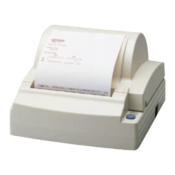
- Seite 1 LINE THERMAL PRINTER MODEL iDP3240 User’s Manual...
- Seite 2 WEEE MARK...
-
Seite 3: Declaration Of Conformity
WARNING : This is a Class A product. In a domestic environment this product may cause radio interference in which case the user may be required to take adequate measures. CITIZEN is registered trade mark of CITIZEN WATCH CO., LTD., Japan CITIZEN es una marca registrada de CITIZEN WATCH CO., LTD., Japón Windows codepage is a registered trademark of Microsoft Corporation —... -
Seite 4: Important Safety Instructions
• This product should be operated from the type of power source indicated on the marking label. If you are not sure of the type of power available, consult your CITIZEN SYSTEMS dealer or local power company. -
Seite 5: Wichtige Sicherheitsanweisungen
WICHTIGE SICHERHEITSANWEISUNGEN • Lesen Sie die nachfolgenden Anweisungen sorgfältig durch und bewahren Sie sie auf. • Befolgen Sie alle auf dem Drucker vermerkten Hinweise und Anweisungen. Vor dem Reinigen grundsätzlich Stecker aus der Steckdose ziehen. Keine Flüssigkeiten oder Aerosolreiniger benutzen. Nut mit einem feuchten Tuch abwischen. •... - Seite 6 IMPORTANT: This equipment generates, uses, and can radiate radio frequency energy and if not installed and used in accordance with the instruction manual, may cause interference to radio communications. It has been tested and found to comply with the limits for a Class A computing device pursuant to Subpart J of Part 15 of FCC Rules, which are designed to provide reasonable protection against such interference when operated in a commercial environment.
-
Seite 7: General Precautions
GENERAL PRECAUTIONS • Prior to using the iDP3240 Printer, be sure to read this User’s Manual thoroughly. Please keep it handy so that you can refer to it whenever necessary. • The information contained herein may be changed without prior notice. -
Seite 8: Safety Precautions
User’s Manual to indicate important items to be strictly observed. • The following describes the degrees of hazards and damages that can occur if the iDP3240 Printer is incorrectly operated without observing the instructions indicated by the warning symbols. WARNING Negligence of the precautions indicated by this symbol may result in death or serious injuries. - Seite 9 WARNING G Never handle the iDP3240 Printer in the manners descried below; otherwise, it may be damaged, get out of order or overheated, possibly causing smoke, fire or electric shock. If the printer is damaged or breaks down, be sure to turn off the power, disconnect the power plug from the wall outlet, and contact your CITIZEN SYSTEMS dealer.
-
Seite 10: Precautions For Installation
PRECAUTIONS FOR INSTALLATION • Do not use or store the iDP3240 Printer in a place exposed to heat of fire, moisture or direct sunlight, or in a place where the prescribed operating temperature and humidity are not met, or in a place exposed to oily mist, iron powder or dust;... - Seite 11 PRECAUTIONS FOR HANDLING Observe the following precautions to use the iDP3240 Printer correctly and avoid troubles from occurring. • Do not use any other power supply than the specified AC adapter. • Do not allow the printer to start printing when there is no recording paper installed.
- Seite 12 In the position indicated below, a label is provided to alert your attention. Read the cautionary information on it, and handle the printer properly. This label alerts you to the print head as it becames HOT, and if you touch it, you may get burnt.
-
Seite 13: Daily Maintenance
DAILY MAINTENANCE • Prior to start maintenance work, be sure to turn off the printer. • When cleaning the platen, use a cotton swab applied with ethyl alcohol and wipe off stains. Platen CAUTION: Avoid cleaning the print head immediately after printing is finished. The print head is HOT. - Seite 14 DAILY MAINTENANCE Cleaning the print head 1 Turn off the power of the printer. 2 Remove the platen roller unit. Refer to “4.6 Removing paper Jams”. 3 Using a gauze impregnated with a small amount of alcohol, wipe off stains and dust on the heat-emitting surface of the head.
-
Seite 15: Inhaltsverzeichnis
2.3.2 Print Position and Barcode Printing ..........7 2.3.3 Cutter Position ................... 8 3. OUTER APPEARANCE AND COMPONENT PARTS ....9 3.1 iDP3240 ...................... 9 4. OPERATION ................10 4.1 Connecting the AC Adapter and AC Power Cord ......... 10 4.2 Connecting Interface Cables .............. - Seite 16 6. PARALLEL INTERFACE ............. 29 6.1 Bidirectional Parallel Interface (IEEE1284) ..........29 6.1.1 Compatibility Mode (Host → Printer communication : Centronics compliant) ..............29 6.1.2 Reverse Mode (Printer → Host communication) ......29 6.1.3 Connector Pin Configuration ............30 6.2 Description of Input and Output Signals ..........31 6.2.1 Input and Output Signals ...............
- Seite 17 10. PRINT CONTROL FUNCTIONS ..........42 10.1 Command List ..................42 10.2 Command Details .................. 45 10.2.1 Description of Each Item .............. 45 10.2.2 Command Details ................46 11. CHARACTER CODES TABLE ..........141 11.1 Code page .................... 141 11.1.1 Codepage 00H to 7FH & PC437 (USA, European Standard) ..141 11.1.2 Codepage Katakana (Japanese) ..........
- Seite 18 14. APPENDIX 3. IDENTIFICATION OF SEND STATUS ....166 15. APPENDIX 4. OUTLINE DRAWING........167 15.1 iDP3240 ....................167 15.2 AC Adapter (31AD) ................168 16. APPENDIX 5. BLOCK DIAGRAM .......... 169 — xvi —...
- Seite 19 <<< German >>> INHALT 4. BETRIEB .................. 179 4.1 Anschließen des Netzteils und Netzkabels ......... 179 4.2 Anschließen der Schnittstellenkabel ........... 180 4.3 Anschließen des Drawer Kickout-Steckers ......... 181 4.4 Einlegen / Auswechseln von Papierrollen ........... 182 4.4.1 Einlegen von Papierrollen ............182 4.4.2 Einlegen von Papierrollen bei deaktiviertem einfachen Ladevorgang ..............
- Seite 20 7. SERIELLE SCHNITTSTELLE ........... 203 7.1 Technische Daten .................. 203 7.2 Belegung der Anschlußstifte ..............204 7.3 Beschreibung der Eingangs- und Ausgangssignale ......205 7.3.1 Eingangs- und Ausgangssignale ..........205 7.3.2 Fehlererkennung ................206 7.3.3 Datenempfangssteuerung ............206 7.3.4 Pufferung ..................206 7.3.5 Elektrische Kenndaten ..............
-
Seite 21: General Outline
1. GENERAL OUTLINE The iDP3240 is a compact-sized, line thermal printer developed for a variety of applications. It has abundant built-in features, and can be used as a data communication terminal, pos terminal, kitchen terminal and for other applications. 1.1 Features •... -
Seite 22: Unpacking
1.2 Unpacking When unpacking the printer, confirm that the following are provided: • Printer .................... 1 unit • Sample paper roll ................. 1 piece • AC adapter ..................1 piece • AC power cord ................1 piece • User’s manual (This book) ............1 piece Sample Printer paper roll... -
Seite 23: Before Using The Printer
1.3 Before using the printer Before using the printer, remove the head protective paper using the following procedure: 1 Open the printer cover. 2 Pull the platen levers in the direction shown. 3 Pull out the protective paper in the direction of the arrow. When the printer is not used for a prolonged period of time, insert a sheet of printing paper in use between the platen roller and the head. -
Seite 24: Basic Specifications
2. BASIC SPECIFICATIONS 2.1 Model Classification The printer models are classified by the following designation method: iDP3240 - R F 120 Model Name Attached power cord spec 120: For AC 120 V 230: For AC 230 V Character Set F: International... -
Seite 25: Basic Specifications
Safety Standard* UL, C-UL, FCC Class A TUV, GS, CE marking The number of print columns can be selected with the DIP switch. Represents the safety standards acquired when CITIZEN SYSTEMS-made adapters (31AD series) are used. — 5 —... -
Seite 26: Print Paper Specifications
• Use of paper other than the specified papers may cause a difference in print density from the CITIZEN SYSTEMS specifications. In that case, you can select an appropriate print density with a DIP switch. (See “5. SETTING DIP SWITCHES”) •... -
Seite 27: Print Position And Barcode Printing
2.3.2 Print Position and Barcode Printing Roll paper width 112 mm provided: Paper width 112 mm applies to printing area 103.5 mm (832 dots), and both left and right margins each ca. 4.25 mm. Paper width 112 mm 0.125 mm Print area 103.5 (90) mm The values in ( ) are for when the... -
Seite 28: Cutter Position
2.3.3 Cutter Position Paper outlet slot Auto cutting position Top print line — 8 —... -
Seite 29: Outer Appearance And Component Parts
3. OUTER APPEARANCE AND COMPONENT PARTS 3.1 iDP3240 Printer cover Top cover Power switch POWER lamp ERROR lamp FEED switch Power Interface Drawer Kick-Out Grounding Connector Connector Connector Terminal — 9 —... -
Seite 30: Operation
4. OPERATION 4.1 Connecting the AC Adapter and AC Power Cord Turn off the power of the printer. With the flat side of the AC adapter’s cable connector facing upward, insert the cable connector into the power connector on the back side of Cable the printer. -
Seite 31: Connecting Interface Cables
4.2 Connecting Interface Cables Serial interface connector Turn off the power of the printer. (As well as the host computer connected.) Serial interface Orienting the interface cable cable terminal correctly, insert it into the interface connector. Secure the cable terminal as shown below. -
Seite 32: Connecting The Drawer Kick-Out Connector
4.3 Connecting the Drawer Kick-Out Connector Turn off the power of the printer. Drawer kick-out connector Orienting the Drawer Kick-Out Cable Connector correctly, insert it into the Drawer Kick-Out Connector on the back of the printer. Fasten the ground wire to the ground connector on the printer with a screw. -
Seite 33: Setting / Replacing Paper Rolls
4.4 Setting / Replacing Paper Rolls 4.4.1 Setting Paper Rolls Turn on the power of the printer. Placing your hands on the small hollows on both sides of the printer cover, lift the cover up until it comes to a stop. Small hollows Cut the end of the paper roll at right... - Seite 34 Check the winding direction of the paper roll, and then place it into the paper roll holder in the Top cover. With the paper roll placed between the platen levers on both sides of the printer, pull the end of the paper roll out up to the end of the Top Platen lever cover, and close the printer cover.
- Seite 35 CAUTION: • Always use the specified types of paper roll. • Use of other types of paper roll may not be able to guarantee the specified print quality or service life of the printer. • Pull out the end of the paper roll up to the end of the upper cover. The end of the paper should not go beyond or short of the end of the Top cover.
-
Seite 36: Setting Paper Rolls When Easy Loading Is Disabled
4.4.2 Setting Paper Rolls when Easy Loading is Disabled (“5.2” DS1-3 ON) Follow steps 1 to 4 in “4.4.1 Setting Paper Rolls”. Insert the end of the paper roll straight between the platen roller and the head. The paper is automatically pulled in by the platen roller and guided into the auto-cutter. -
Seite 37: Removing The Remainder Of Paper Rolls
4.5 Removing the Remainder of Paper Rolls Open the printer cover. Platen lever Pull both platen levers in the direction of the arrows to separate the platen roller from the head, and then pull out the paper roll. Printer cover CAUTION: When removing the paper roll (in either direction), the platen levers must be pulled. -
Seite 38: Removing Paper Jams
4.6 Removing Paper Jams Chassis hook Turn off the power of the printer. Open the printer cover. Cut the paper near the paper insertion slot. Move the head springs on both sides in the direction of arrows to unhook them from the chassis hooks, and lift them up. -
Seite 39: Releasing A Locked Cutter
4.7 Releasing a Locked Cutter Remove any paper in the paper path following the procedure in “4.6 Removing Paper Jams”. Turn on the power of printer. The auto cutter initializes itself, returning the cutter blade to the normal position. The alarm condition is also Emergency knob cleared. -
Seite 40: Cleaning The Print Head
4.8 Cleaning the Print Head Remove the platen roller unit Platen roller unit following the procedure in “4.6 Removing Paper Jams”. Wipe off stains, such as dust and the like, on the heating element of the head using a cotton swab impregnated with ethyl alcohol. -
Seite 41: Operation Panel And Error Indication
4.9 Operation Panel and Error Indication POWER lamp (Green) Lights when the power is turned on. It blinks when a memory check error has occurred. ERROR lamp (Red) Lights or blinks to show different error states. Error indication POWER LED ERROR LED Recovery method Memory check error... - Seite 42 Description of errors Cover open: When you open the printer cover, the cover open sensor is activated, causing the ERROR LED to light and the printing operation to stop. However, by making a proper setting on the DIP switch, the paper can be fed through the printer with the cover open.
-
Seite 43: Self Printing
4.10 Self Printing Performing Self Printing If you press the POWER switch while holding down the FEED switch, self printing is performed. POWER switch POWER lamp (Green) ERROR lamp (Red) FEED switch — 23 —... -
Seite 44: Hexadecimal Dump
4.11 Hexadecimal Dump Hexadecimal dump function allows data sent from the host computer to be printed in hexadecimal numbers as well as in characters corresponding to the numbers. Starting hexadecimal dump Open the top cover. While pressing the FEED switch, turn ➀... -
Seite 45: Setting Dip Switches
5. SETTING DIP SWITCHES 5.1 Location of DIP Switches To access the DIP switches, follow these steps: Turn off the power of the printer. Disconnect the Power Unit Connector. Remove the back cover. (Unfasten the two screws and lift the back cover in the direction of the arrow.) Parallel Interface Serial Interface... -
Seite 46: Table For Setting Dip Switches
5.2 Table for Setting DIP Switches DIP switch 1 Function Factory setting Auto cutter Available Not available Cover open Invalid Valid Easy Loading Invalid Valid Print columns 60 columns 69 columns CR mode LF Operation Ignored Input buffer 4K bytes 64K bytes Print density See the table below... - Seite 47 DIP switch 2 Function Factory setting Character code OFF * Character code OFF * See the table below. Character code OFF * Character code OFF * JIS/Shift JIS Shift JIS • Off-line Condition for BUSY Reception • Reception to occur buffer full buffer full Unused...
- Seite 48 DIP switch 3 Function Factory setting Bit length 7 bits 8 bits Parity Available Not available Odd /Even Even number Odd number Communication mode XON/XOFF DTR/DSR DIP switch 4 Function Factory setting Baud rate See the table below. Baud rate Reset INIT Reset...
-
Seite 49: Parallel Interface
6. PARALLEL INTERFACE 6.1 Bidirectional Parallel Interface (IEEE1284) 6.1.1 Compatibility Mode (Host → Printer communication : Centronics compliant) • General description This printer provides Compatibility Mode, which specifies the Centronics interface conventionally used for a wide variety of applications. • Specifications Data transfer method: 8-bit parallel Synchronizing method:... -
Seite 50: Connector Pin Configuration
6.1.3 Connector Pin Configuration Source Compatibility Mode Nibble Mode Byte Mode Host nStrobe HostClk HostClk Host/Ptr Data0(LSB) Data0(LSB) Data0(LSB) Host/Ptr Data1 Data1 Data1 Host/Ptr Data2 Data2 Data2 Host/Ptr Data3 Data3 Data3 Host/Ptr Data4 Data4 Data4 Host/Ptr Data5 Data5 Data5 Host/Ptr Data6 Data6 Data6... -
Seite 51: Description Of Input And Output Signals
CAUTION: • The first letter “n” of each signal name indicates that the signal is active “L”. • If any one of the above signals is not available, bidirectional communication cannot be accomplished. • In interfacing signals, be sure to use twist-paired wires for signal lines, and the return side must be connected to signal ground level. -
Seite 52: Electrical Characteristics
6.2.2 Electrical Characteristics Input signal level (nStrobe, Data 0-7) All the input signals are at the C-MOS level. “HIGH” level: 4.0 V minimum “LOW” level: 0.9 V maximum Output signal level All the output signals are at the C-MOS level. “HIGH”... -
Seite 53: Timing Chart (Compatibility Mode)
6.2.3 Timing Chart (Compatibility Mode) Data input and print timing Power Data nStrobe Busy nAck T1, T2, T3: 0.5 µs MIN 270 ns MAX 2.3 µs TYP 500 ms MIN (At power- on) 6.2.4 Data Reception Control When the Busy signal is at “LOW”, the printer can receive data from the host computer, but when at “HIGH”, data reception is not possible. -
Seite 54: Serial Interface
7. SERIAL INTERFACE 7.1 Specifications (1) Synchronizing system Asynchronous (2) Baud rate 2400, 4800, 9600, or 19200 bps (User selectable) (3) Configuration of one word Start bit: 1-bit Data bits: 7 or 8-bits (User selectable) Parity bit: Odd, even, or none (User selectable) Stop bit: 1-bit or more (4) Signal polarity RS-232C... -
Seite 55: Connector Pin Configuration
7.2 Connector Pin Configuration Signal name Input/output Function — Grounding for safety Output Transferred data Input Received data Output Same as DTR Data set ready or reset Input (Selected with a DIP switch) — Ground for signals Output Printer Busy signal INIT Input Reset (Selected with a DIP switch) -
Seite 56: Description Of Input And Output Signals
7.3 Description of Input and Output Signals 7.3.1 Input and Output Signals (1) RD This is a serial reception data signal. When a framing error, overrun error or parity error occurs, the data containing the error is printed as a “?”. (2) DTR, RTS When this signal is Ready, you can write data or commands into the input buffer. -
Seite 57: Error Detection
7.3.2 Error Detection Detection of parity errors, framing errors, and overrun errors is provided with this printer. When an error is detected, the data containing the error is stored in the buffer as a “?”. (1) Framing error If a space state is detected at the timing of stop bit detection, this indicates that an error has occurred. -
Seite 58: Electrical Characteristics
7.3.5 Electrical Characteristics RS-232C circuit Input (RD, DSR, INIT) [Printer Side] [Host Side] Equivalent to MAX232 Output (DTR, TD, RTS) [Printer Side] [Host Side] Equivalent to MAX232 — 38 —... -
Seite 59: Drawer Kick-Out Connector And Power Connector
8. DRAWER KICK-OUT CONNECTOR AND POWER CONNECTOR 8.1 Specifications of Drawer Kick-Out Connector 8.1.1 Drawer Kick-Out drive signal A pulse specified by ESC p, DLE DC4 is output. In parallel interface mode, the SW(+) state can be confirmed at No. 34 pin of the interface connector or by the DLE EOT, GS a and GS r commands at the serial/parallel interface. -
Seite 60: Drive Circuit
8.1.4 Drive Circuit 8.2 Specifications of the Power Connector The following shows the power connector from the dedicated AC adapter. Pin configuration of Power connector (Pin number and function) +24V Power connector: TCS7960-53-2010 (Hosiden) or equivalent Applicable connector: TCP8927-63-1100 (Hosiden) or equivalent TCP8927-53-1100 (Hosiden) or equivalent —... -
Seite 61: Maintenance And Service
9. MAINTENANCE AND SERVICE For the information on maintenance and service, please contact our dealer. — 41 —... -
Seite 62: Print Control Functions
10. PRINT CONTROL FUNCTIONS 10.1 Command List No. Command Function Mode Code Page Horizontal tab S.P. <09>H Printing and paper feed S.P. <0A>H Back to printing S.P. <0D>H Printing in PAGE MODE and returning to <0C>H STANDARD MODE Canceling print data in PAGE MODE <18>H DLE EOT Sending status in real-time S.P. -
Seite 63: No. Command
No. Command Function Mode Code Page Selecting the character printing direction 30 ESC T <1B>H<54>H<n> in PAGE MODE Specifying/Canceling 90°-right-turned 31 ESC V <1B>H<56>H<n> characters <1B>H<57>H<xL><xH> 32 ESC W Defining the print area in PAGE MODE <yL><yH><dxL><dxH> <dyL><dyH> 33 ESC \ Specifying the relative position S.P. - Seite 64 No. Command Function Mode Code Page <1D>H<57>H<nL> 54 GS W Setting the print area width S.P.* <nH> Specifying the relative vertical position <1D>H<5C>H<nL> 55 GS \ S.P.* of a character in PAGE MODE <nH> <1D>H<5E>H<n1> 56 GS ^ Executing the macro S.P.
-
Seite 65: Command Details
10.2 Command Details 10.2.1 Description of Each Item XXXX [Function] The name of a command. [Code] The string of codes comprising the command is represented by < >H for hexadecimal numbers, < >B for binary numbers, and < > for decimal numbers, [ ] k denotes the number of repetition of “k”... -
Seite 66: Command Details
10.2.2 Command Details [Function] Horizontal tab [Code] <09>H [Outline] Shifts the printing position to the next horizontal tab position. • Ignored when the next horizontal tab position has not been set. [Caution] • The horizontal tab position is set by ESC D. •... -
Seite 67: Printing And Paper Feed
[Function] Printing and paper feed [Code] <0A>H [Outline] Prints data inside the print buffer and feeds paper based on the line feed amount having been set. • The head of the line becomes the next print starting position. [See Also] ESC 2, ESC 3 [Sample Program] LPRINT “AAA”... -
Seite 68: Back To Printing
[Function] Back to printing [Code] <0D>H [Outline] 1) When DSW1-5 is OFF: This command is ignored. 2) When DSW1-5 is ON: With data held inside the internal print buffer, printing and line feed are performed. Without data inside the internal print buffer, however, only line feed is performed. -
Seite 69: Printing In Page Mode And Returning To Standard Mode
[Function] Printing in PAGE MODE and returning to STANDARD MODE [Code] <0C>H [Outline] Executes a batch printout of the data mapped in the entire print area, and then returns to STANDARD MODE. [Caution] • All mapped data is erased after printout. •... -
Seite 70: Can
[Function] Canceling print data in PAGE MODE [Code] <18>H [Outline] Erases all data contained in the currently effective print area in PAGE MODE. [Caution] • This command is only effective when PAGE MODE is selected. • If any data mapped in the previously established print area overlaps the data in the currently set print area, the overlapped data in the previously established area will be erased when this command is executed. -
Seite 71: Dle Eot Sending Status In Real-Time
DLE EOT n [Function] Sending status in real-time [Code] <10>H<04>H<n> [Range] [Outline] Sends in real-time the status specified by “n”. n = 1: Printer status n = 2: Status caused by an offline condition n = 3: Status caused by an error n = 4: Continuous paper detector status [Caution] •... - Seite 72 (1) Printer status (When n = 1 is specified) Status Hex. Decimal Unused (Fixed at 0) Unused (Fixed at 1) Status of pin 3 of Drawer Kick-Out Connector = L Status of pin 3 of Drawer Kick-Out Connector = H Online status Offline status Unused (Fixed at 1)
- Seite 73 (3) Status caused by an error (when n = 3 is specified) Status Hex. Decimal Unused (Fixed at 0) Unused (Fixed at 1) Undefined — — Auto cutter error not occurred Auto cutter error occurred Unused (Fixed at 1) Unrecoverable error not occurred Unrecoverable error occurred Auto recovery error not occurred Auto recovery error occurred...
- Seite 74 DLE ENQ n [Function] Real-time request to printer [Code] <10>H<05>H<n> [Range] [Outline] The printer responds in real-time to the requests from the host. n = 1: After recovering from an error, the printer resumes printing from the beginning of the line where the error occurred.
-
Seite 75: Dle Dc4 Outputting Specified Pulse In Real-Time
DLE DC4 n m t [Function] Outputting specified pulse in real-time. [Code] <10>H<14>H<n><m><t> [Range] n=1, m=0,1 [Outline] A signal specified with “t” is output to the connector pin specified with “m”. Connector pin Pin No. 2 of drawer Kick-Out Connector Pin No. -
Seite 76: Esc Ff
ESC FF [Function] Printing data in PAGE MODE [Code] <1B>H<0C>H [Outline] Prints out all the data mapped in the entire print area in PAGE MODE. [Caution] • This command is only effective when PAGE MODE is selected. • Mapped data, as well as the ESC T and ESC W settings, and the character mapping position are held even after printing. -
Seite 77: Setting The Right Spacing Of The Character
ESC SP n [Function] Setting the right spacing of the character [Code] <1B>H<20>H<n> [Range] Sets the right spacing of character to [n × basic calculation pitch]. [Outline] [Caution] • If the horizontal magnification of character is set, the right spacing increases with the magnification. •... - Seite 78 [Sample Program] LPRINT CHR$(&H1B) + “ ” + CHR$(0) ; LPRINT “AAAAA” + CHR$(&HA) ; LPRINT CHR$(&H1B) + “ ” + CHR$(1) ; LPRINT “AAAAA” + CHR$(&HA) ; LPRINT CHR$(&H1B) + “ ” + CHR$(12) ; LPRINT “AAAAA” + CHR$(&HA) ; [Print Results] ←...
-
Seite 79: Collectively Specifying The Printing Mode
ESC ! n [Function] Collectively specifying the printing mode [Code] <1B>H<21>H<n> [Range] [Outline] Printing mode is assigned. Value Function Character Font Font A Font B Undefined Undefined Emphasis Canceled Specified Double height Canceled Specified Double width Canceled Specified Undefined Underline Canceled Specified [Caution]... - Seite 80 [Sample Program] LPRINT CHR$(&H1B) + “!” + CHR$($H00) + “H” ; LPRINT CHR$(&H1B) + “!” + CHR$($H01) + “H” ; LPRINT CHR$(&H1B) + “!” + CHR$($H08) + “H” ; LPRINT CHR$(&H1B) + “!” + CHR$($H10) + “H” ; LPRINT CHR$(&H1B) + “!” + CHR$($H20) + “H” ; LPRINT CHR$(&H1B) + “!”...
-
Seite 81: Specifying The Absolute Positions
ESC $ n1 n2 [Function] Specifying the absolute positions [Code] <1B>H<24>H<n1><n2> [Range] [Outline] The printing start position is moved to a position specified with (n1 + (n2 × 256) ) × basic calculation pitch from the beginning (left margin) of a line. •... - Seite 82 [Sample Program] LPRINT CHR$(&H1B) + “$” ; LPRINT CHR$(0) + CHR$(0) + “A” ; LPRINT CHR$(&H1B) + “$” ; LPRINT CHR$(50) + CHR$(0) + “B” ; LPRINT CHR$(&H1B) + “$” ; LPRINT CHR$(0) + CHR$(1) + “C” ; LPRINT CHR$(&HA) ; LPRINT CHR$(&H1B) + “$”...
-
Seite 83: Specifying/Canceling Download Character Set S.p. H H
ESC % n [Function] Specifying/Canceling download character set [Code] <1B>H<25>H<n> [Range] [Outline] Specifying/canceling download characters. • Only the lowest bit (n0) is valid for n. Function Canceling download character set Specifying download character set [Caution] Download characters and download bit images cannot be defined simultaneously. -
Seite 84: Defining The Download Characters
ESC & s n m [a [p] s × a] m–n+1 [Function] Defining the download characters <1B>H<26>H<s>H<n><m>[<a><p1><p2> ⋅ ⋅ <ps × a>]m-n+1 [Code] [Range] s = 3 12 (Font A) 9 (Font B) p1 ⋅ ⋅ ps × a [Outline] Defines the fonts of download characters. - Seite 85 [Example] 12dot 9dot p1 p4 p1 p4 24dot 24dot Font A Font B Create each data bit by setting “1” for a printed dot and “0” for an unprinted dot. [Sample Program] Refer to Sample Program and Print Results for ESC % on page 63.
-
Seite 86: Esc
m n1 n2 [ d ] k [Function] Specifying the bit image mode [Code] <1B>H<2A>H<m><n1><n2> [<d>] k [Range] m= 0, 1, 32, 33 k = n1 + 256 × n2 (m = 0, 1) k = (n1+ 256 × n2) × 3 (m = 32, 33) [Outline] According to the number of dots specified in “n1”, “n2”, specify the bit image of mode “m”. - Seite 87 [Sample Program] LPRINT CHR$(&H1B) + “ ”; LPRINT CHR$(0) + CHR$(20) + CHR$(0); IMG1: GOSUB IMG1 LPRINT CHR$(&HFF); LPRINT CHR$(&HA); FOR I=1 TO 18 LPRINT CHR$(&H1B + “ ”; LPRINT CHR$(&H85); LPRINT CHR$(1) + CHR$(20) + CHR$(0); NEXT I GOSUB IMG1 LPRINT CHR$(&HFF);...
-
Seite 88: Specifying/Canceling Underline
ESC – n [Function] Specifying/Canceling underline [Code] <1B>H<2D>H<n> [Range] [Outline] Specifying/canceling an underline. n=0, 48 Canceling an underline n=1, 49 Specifying an underline for 1-dot width n=2, 50 Specifying an underline for 2-dots width [Caution] • An underline is attached to the full character width. It is, however, not attached to the part having been skipped by horizontal tab command. -
Seite 89: Esc 2
ESC 2 [Function] Specifying 1/6-inch line feed rate [Code] <1B>H<32>H [Outline] The line feed rate per line is specified by 1/6 inch. [Caution] Line feed rate can be specified respectively for both STANDARD MODE and PAGE MODE. [Sample Program] LPRINT “AAAAA” + CHR$(&HA); LPRINT CHR$(&H1B) + “3”... -
Seite 90: Setting Line Feed Width
ESC 3 n [Function] Setting line feed width [Code] <1B>H<33>H<n> [Range] Sets the line feed width per line to [n × basic calculation pitch] . [Outline] [Caution] The line feed width can be set separately for the STANDARD and PAGE MODES. The basic calculation pitch currently set is used. -
Seite 91: Data Input Control
ESC = n [Function] Data input control [Code] <1B>H<3D>H<n> [Range] [Outline] Selecting equipment for which data input from the host is valid. • Each bit of “n” indicates as follows: Value Equipment Printer Invalid Valid Not defined Not defined Not defined Not defined Not defined Not defined... -
Seite 92: Deleting Download Characters
ESC ? n [Function] Deleting download characters [Code] <1B>H<3F>H<n> [Range] [Outline] Deletes the downloaded characters of specified code. [Caution] • Specifies the character code for the defined pattern to be deleted. After the deletion, internal characters are printed. • This command deletes the code-defined pattern of the character font selected currently. -
Seite 93: Esc
ESC @ [Function] Initializing the printer [Code] <1B>H<40>H [Outline] Clears data stored in the print buffer and brings various settings to the initial state (Default state). [Caution] • The settings of DIP switches are not read again. • Data inside the internal input buffer is not cleared. •... -
Seite 94: Setting Horizontal Tab Position
ESC D { n } k NUL [Function] Setting horizontal tab position [Code] <1B>H<44>H [<n>] k<00> [Range] [Outline] Specifying a horizontal tab position. • “n” indicates the number of columns from the beginning (left margin) to the horizontal tab position. Note, however, that “n= set position –... -
Seite 95: Specifying/Canceling Emphasis Printing
ESC E n [Function] Specifying/Canceling Emphasis Printing [Code] <1B>H<45>H<n> [Range] [Outline] Specifying/canceling the emphasized characters. • “n” is valid only for the lowest bit (n0). • Control by the lowest bit (n0) is shown as follows: Type Canceling emphasis printing Specifying emphasis printing •... -
Seite 96: Specifying/Canceling Double Strike Printing S.p. H H
ESC G n [Function] Specifying/Canceling Double strike printing [Code] <1B>H<47>H<n> [Range] [Outline] Specifying/canceling the double strike printing. • “n” is valid only for the lowest bit (n0). • Control by “n” is shown as follows. Type Canceling double strike printing Specifying double strike printing This is effective to all characters. -
Seite 97: Printing And Feeding Paper
ESC J n [Function] Printing and feeding paper [Code] <1B>H<4A>H<n> [Range] Prints the data held in the print buffer and feeds paper by [n × [Outline] basic calculation pitch] inches. The beginning of the line is taken as the next print start position. [Caution] The line feed width can be set separately for the STANDARD and PAGE MODES. -
Seite 98: Esc L
ESC L [Function] Selecting PAGE MODE [Code] <1B>H<4C>H [Outline] Switches from STANDARD MODE to PAGE MODE. [Caution] • This command is only effective if it entered at the beginning of a line. • This command is not effective if it is entered when in PAGE MODE. -
Seite 99: Selection Of Character Fonts
ESC M n [Function] Selection of character fonts [Code] <1B>H<4D>H<n> [Definition value] n=0, 1, 48, 49 [Outline] Selects character fonts. Function Selection of font A (12 × 24) 0, 48 Selection of font B (9 × 24) 1, 49 [Details] Fonts can also be selected with ESC !, but are only valid with the command that is set last. -
Seite 100: Selecting The International Character Set
ESC R n [Function] Selecting the international character set [Code] <1B>H<52>H<n> [Range] [Outline] Depending on the value of “n”, one of the following character sets is specified; Character Set U.S.A. France Germany U.K. Denmark I Sweden Italy Spain I Japan Norway Denmark II Spain II... -
Seite 101: Esc S
ESC S [Function] Selecting STANDARD MODE [Code] <1B>H<53>H [Outline] Switches from PAGE MODE to STANDARD MODE. [Caution] • This command is only effective if it is entered when in PAGE MODE. • Any data mapped in PAGE MODE is erased. •... -
Seite 102: Esc
ESC T n [Function] Selecting the character printing direction in PAGE MODE [Code] <1B>H<54>H<n> [Range] [Outline] Selects the direction and start point of character printing in PAGE MODE. Printing direction Start point 0, 48 Left to right Top left (“A” in the figure) 1, 49 Bottom to top Bottom left (“B”... -
Seite 103: Specifying/Canceling 90°-Right-Turned Characters
ESC V n [Function] Specifying/Canceling 90°-right-turned characters [Code] <1B>H<56>H<n> [Range] n = 0, 1, 48, 49 [Outline] Specifying/canceling 90°-right- turned characters. Function 0, 48 Canceling 90°-right- turned Characters 1, 49 Specifying 90°-right- turned Characters [Caution] No underlines are attached to 90°-right- turned characters. The settings of this command have no effect on PAGE MODE, but items set in PAGE MODE are valid even after STANDARD MODE resumes. -
Seite 104: Defining The Print Area In Page Mode
ESC W xL xH yL yH dxL dxH dyL dyH [Function] Defining the print area in PAGE MODE [Code] <1B>H<57>H<xL><xH><yL><yH><dxL><dxH><dyL><dyH> [Range] xL, xH, yL, yH, dxL, dxH, dyL, dyH 255, except for dxL = dxH = 0 or dyL = dyH = 0 [Outline] Defines the location and size of the print area. - Seite 105 • The figure below illustrates the print area, where X = horizontal start point, Y=vertical start point, Dx=horizontal length, and Dy=vertical length. Paper ↑ Paper Feed Direction Print Area The printable area for this printer is approximately 104.1 mm (832/203 inches) horizontally and 117 mm (1662/360 inches) vertically.
-
Seite 106: Specifying The Relative Position
ESC \ nL nH [Function] Specifying the relative position [Code] <1B>H<5C>H<nL><nH> [Range] [Outline] This command specifies the next print start position in a relative position with respect to the current position. The next print start position will be at a point of [(nL + nH × 256) × basic calculation pitch] away from the current position. -
Seite 107: Aligning The Characters
ESC a n [Function] Aligning the characters [Code] <1B>H<61>H<n> [Range] [Outline] All the printed data within one line are aligned in the specified position. • Depending on the value “n”, positional alignment is carried out as shown in the table below: Position 0,48 Left end alignment... -
Seite 108: Esc C3
ESC c 3 n [Function] Selecting the Paper Sensor valid for a paper end signal output [Code] <1B>H<63>H<33>H<n> [Range] [Outline] This command selects by which Paper Sensor a paper end signal should be output. Each bit for “n” has the following meaning: Value Position Paper Near-end... -
Seite 109: Esc C4
ESC c 4 n [Function] Selecting the Paper Near-end Sensor valid for print stop [Code] <1B>H<63>H<34>H<n> [Range] [Outline] This command selects the Paper Near-end Sensor which helps to stop printing when the paper supply almost runs out. Each bit for “n” has the following meaning: Value Position Paper Near-end... -
Seite 110: Esc C5
ESC c 5 n [Function] Enabling/Disabling the panel switches [Code] <1B>H<63>H<35>H<n> [Range] [Outline] Enabling/disabling the FEED switch. • “n” is valid only in the lowest bit. Condition FEED switch valid FEED switch invalid [Caution] When the panel switch is disabled with this command, the FEED switch is also disabled. -
Seite 111: Printing And Feeding The Paper By "N" Lines S.p. H H
ESC d n [Function] Printing and feeding the paper by “n” lines [Code] <1B>H<64>H<n> [Range] [Outline] Prints data in the print buffer and feeds paper by “n” lines. • Specified lines do not remain. • The beginning of the line is specified as the next print start position. -
Seite 112: Generating The Specified Pulses
ESC p m n1 n2 [Function] Generating the specified pulses [Code] <1B>H<70>H<m><n1><n2> [Range] m = 0, 1, 48, 49 [Outline] The signals specified by “n1” and “n2” are output to the connector pin specified by “m”. • “m” has the followings. Connector Pin 0, 48 Drawer Kick-Out pin No.2... -
Seite 113: Selecting The Character Code Table
ESC t n [Function] Selecting the character code table [Code] <1B>H<74>H<n> [Range] 9, n = 255 [Outline] Selecting the character code table: The character code table is selected based on the value of “n”. Character Code Table Codepage PC437 (USA, European Standard) Codepage Katakana (Japanese) Codepage PC850 (Multilingual) Codepage PC860 (Portuguese) -
Seite 114: Specifying/Canceling The Inverted Characters
ESC { n [Function] Specifying/Canceling the inverted characters [Code] <1B>H<7B>H<n> [Range] [Outline] Specifying/canceling inverted characters. • “n” is valid only for the lowest bit. Condition Canceling inverted characters. Specifying inverted characters. [Caution] • Inverted printing means printing the line turned 180°. •... -
Seite 115: Specifying The Character Size
GS ! n [Function] Specifying the character size [Code] <1D>H<21>H<n> [Range] 255, where: vertical magnification horizontal magnification [Outline] Specifies the character size (Vertical and horizontal magnification). Value Function Hex. Number Decimal Number Vertical magnification Refer to Table 2, “Vertical specification Magnification”. - Seite 116 • If characters of different vertical magnification are contained in a line, the baseline of each character is lined up. • Horizontal and vertical magnification can also be specified/ canceled by ESC !. The ESC ! or GS ! command, whichever is handled last, becomes effective.
-
Seite 117: Specifying The Absolute Vertical Position Of Characters In Page Mode
GS $ nL nH [Function] Specifying the absolute vertical position of characters in PAGE MODE [Code] <1D>H<24>H<nL><nH> [Range] [Outline] This command is used in PAGE MODE to specify the vertical position of characters at the data mapping start position as an absolute value measured from the start point. -
Seite 118: Defining The Download Bit Image
n1 n2 [ d ] n1 × n2 × 8 [Function] Defining the download bit image <1D>H<2A>H<n1><n2> [< d >] n1 × n2 × 8 [Code] [Range] n1 × n2 1536 [Outline] Defines download bit images of the number of dots specified by n1 and n2. - Seite 119 [Sample Program] GOSUB IMG LPRINT CHR$(&H1D) + “/” + CHR$(0); LPRINT CHR$(&H1D) + “/” + CHR$(1); LPRINT CHR$(&H1D) + “/” + CHR$(2); LPRINT CHR$(&H1D) + “/” + CHR$(3); IMG: n1=10 : n2=5 LPRINT CHR$(&H1D) + “ ”; LPRINT CHR$(n1) + CHR$(n2); FOR J=1 TO n1 FOR I=1 TO n2 LPRINT CHR$(J);...
-
Seite 120: Execution Of Test Printing
GS (A pL pH n m [Function] Execution of test printing [Code] <1D>H<28>H<41>H<pL><pH><n><m> (pL+(pH × 256))=2 (pL=2, pH=0) [Definition] 2, 48 3, 49 [Outline] Specified test printing will be executed. • pL, pH will specify the number of subsequent parameters by (pL+(pH ×... -
Seite 121: Printing The Downloaded Bit Image
GS / m [Function] Printing the downloaded bit image [Code] <1D>H<2F>H<m> [Range] [Outline] Prints downloaded bit image in a mode specified by “m”. Modes that can be selected by “m” are shown below. Dot Density in Dot Density in Mode Name Vertical Direction Horizontal Direction 0,48... -
Seite 122: Starting/Ending Macro Definition
GS : [Function] Starting/Ending macro definition [Code] <1D>H<3A>H [Outline] Specifying starting/ending macro definition. Reception of this command during macro definition signifies ending the macro definition. [Caution] Maximum content available for macro definition is 2048 bytes. A portion exceeding 2048 bytes is not defined. •... -
Seite 123: Specifying/Canceling The Black/White Inverted Printing
GS B n [Function] Specifying/Canceling the black/white inverted printing [Code] <1D>H<42>H<n> [Range] [Outline] This command specifies or cancels the black/white inverted printing. Function The black/white inverted printing is canceled. The black/white inverted printing is specified. [Caution] • Number “n” is only valid in the lowest bit. •... -
Seite 124: Selecting Of Printing Position Of Hri Characters
GS H n [Function] Selecting of printing position of HRI characters [Code] <1D>H<48>H<n> [Range] [Outline] Selecting printing position of HRI characters in printing bar codes. • “n” means the followings. Printing Position 0,48 No printing 1,49 Above the bar code 2,50 Below the bar code 3,51... - Seite 125 [Print Results] No HRI characters Printed above Printed below Printed above and below — 105 —...
-
Seite 126: Sending The Printer Id
<1D>H<49>H<n> [Range] [Outline] Sends the specified printer ID. Type of printer ID Specification Value (Hex.) 1,49 Model ID iDP3240 2,50 Type ID Refer to table “Type ID” below 3,51 ROM version ID As per ROM version Type ID Meaning Hex. -
Seite 127: Setting The Left Margin
GS L nL nH [Function] Setting the left margin [Code] <1D>H<4C>H<nL><nH> [Range] [Outline] This command sets the left margin specified by nL and nH. The value of the left margin is [(nL + nH × 256) × basic calculation pitch]. Printable Area Left Margin Print Area Width... -
Seite 128: Specifying The Basic Calculation Pitch
GS P x y [Function] Specifying the basic calculation pitch [Code] <1D>H<50>H<x><y> [Range] [Outline] This command sets the horizontal basic calculation pitch to approx. 25.4/x mm (1/x inches), and the vertical basic calculation pitch to approx. 25.4/y mm (1/y inches). •... -
Seite 129: Cutting The Paper
GS V m ..(1) GS V m n ..(2) [Function] Cutting the paper [Code] (1) <1D>H<56>H<m> (2) <1D>H<56>H<m><n> [Range] (1) m = 1, m = 49 (2) m = 66 [Outline] Performs the specified paper cutting. Function 1,49 Partial cut (Leaving a bridge area uncut) Paper feed by “cut position + {n ×... - Seite 130 GS W nL nH [Function] Setting the print area width [Code] <1D>H<57>H<nL><nH> [Range] [Outline] Sets the print area width specified by nL and nH. • The print area width will be [(nL + nH × 256) × basic calculation pitch]. Printable Area Left Margin Print Area Width...
- Seite 131 (2) If a sufficient area cannot be provided as a result of step (1), the print area is extended toward the left (So, the left margin is decreased). Printable Area Extended toward the right (2) The left margin Left Margin is trimmed Print Area Width (3) If a sufficient area cannot be provided as a result of step...
- Seite 132 GS \ nL nH [Function] Specifying the relative vertical position of a character in PAGE MODE [Code] <1D>H<5C>H<nL><nH> [Range] [Outline] This command is used in PAGE MODE to specify the vertical position of a character in the data mapping start position, in a relative position with respect to the current position.
- Seite 133 GS ^ n1 n2 n3 [Function] Executing the macro [Code] <1D>H<5E>H<n1><n2><n3> [Range] [Outline] Executing contents defined in macro. n1 : The number of times of macro execution n2 : Waiting time on macro execution Waiting time of n2 × 100 msec is given for every execution. n3 : Macro execution mode n3=0 Continuous execution: The Macro is executed “n1”...
- Seite 134 GS a n [Function] Enabling/Disabling ASB (Automatic Status Back) [Code] <1D>H<61>H<n> [Range] [Outline] This command selects the status item to be addressed by ASB (Automatic Status Back.) Status item addressed by ASB Hex. Decimal Status of pin 3 of Drawer Kick-Out Connector = disabled Status of pin 3 of Drawer Kick-Out Connector = enabled Online/offline status = disabled Online/offline status = enabled...
- Seite 135 (1) 1st byte (Printer information) Status Hex. Decimal Unused (Fixed at 0) Unused (Fixed at 0) Status of pin 3 of Drawer Kick-Out Connector = “L” Status of pin 3 of Drawer Kick-Out Connector = “H” Online status Offline status Unused (Fixed at 1) Cover closed Cover open...
- Seite 136 (4) 4th byte (Paper Sensor information) Status Decimal Undefined — — Undefined — — Undefined — — Undefined — — Unused (Fixed at 0) Undefined — — Undefined — — Unused (Fixed at 0) [Default] DIP Switch 2-6 OFF: n = 0 DIP Switch 2-6 ON: n = 2 [See Also] DLE EOT, GS r, “IDENTIFICATION OF SEND STATUS”...
- Seite 137 GS f n [Function] Selecting the font of HRI characters [Code] <1D>H<66>H<n> [Range] n = 0, 1, 48, 49 [Outline] Selecting the font of HRI characters in printing bar code. The type of font can be selected with “n” as follows: Font Font A (12 ×...
- Seite 138 GS h n [Function] Specifying the height of the bar code [Code] <1D>H<68>H<n> [Range] [Outline] Selecting bar code height. “n” denotes the number of dots in the vertical direction. [Default] n = 162 [Sample Program] Refer to Sample Program and Print Results for GS w on page 131.
- Seite 139 GS k m [d1 ..dk] NUL GS k m n [d1 ..dn] [Function] Printing the bar code [Code] (1) <1D>H<6B>H<m> [d1..dk] NUL (2) <1D>H<6B>H<m><n> [d1..dn] [Range] (1) 0 The definitions of “k” and “d” vary with the bar code system. (2) 65 73 The definitions of “n”...
- Seite 140 [Caution] For (1): • This command ends with a NUL code. • For UPC-A or UPC-E, the bar code is printed when 12 bytes of bar code data have been entered, and the subsequent data is handled as normal data. •...
- Seite 141 For PAGE MODE: • This command only maps the bar code, without performing a printout. After the bar code is mapped, the dot next to the last data item of the bar code is taken as the start position for the next data mapping.
- Seite 142 [Description of Bar Codes] <For print examples, refer to page 126.> UPC-A This bar code, consisting of numerals only, has a fixed length of 12 columns; a 11-column number entered from the host or application software plus a check digit (12th column) automatically calculated inside the printer.
- Seite 143 CODABAR (NW-7) This bar code, consisting of alphanumerics, has a variable length of columns. Available characters include “0 1 2 3 4 5 6 7 8 9 A B C D $ + – . / :”. A start/stop code is required; any one of A, B, C, and D is used.
- Seite 144 CODE128 This bar code consists of 103 bar code characters and three code sets, enabling 128 ASCII code characters to be printed. It has a variable length of columns. • Code set A ASCII characters 00H - 5FH can be represented.
- Seite 145 Special characters Hex. ASCII Code set A Code set B Code set C 7B53 SHIFT SHIFT –N/A– 7B41 –N/A– CODE A CODE A 7B42 CODE B –N/A– CODE B 7B43 CODE C CODE C –N/A– 7B31 FNC1 FNC1 FNC1 7B32 FNC2 FNC2 –N/A–...
- Seite 146 [Description of Bar Codes] UPC-A, UPC-E, JAN-13 (EAN), JAN-8 (EAN), CODE39, ITF, CODABAR, CODE93, CODE128 Type Print Sample Outline of Symbol UPC-A 12-column fixed-length bar code consisting of numerals only. UPC-E 8-column fixed-length bar code consisting of numerals only. Abbreviated version of UPC-A. JAN-13 13-column fixed-length bar code consisting of numerals only.
- Seite 147 GS r n [Function] Sending status [Code] <1D>H<72>H<n> [Range] [Outline] Sends the specified status to the host. n = 1, 49: Sends the Paper Sensor status. n = 2, 50: Sends the Drawer Kick-Out Connector status. [Caution] • When the serial interface is used: For DTR/DSR control: The printer sends the status after verifying that the host is ready to receive.
- Seite 148 • Drawer Kick-Out Connector status (n = 2, 50) Status Hex. Decimal Status of pin 3 of Drawer Kick Connector = “L” Status of pin 3 of Drawer Kick Connector = “H” 01 Undefined — — Undefined — — Undefined —...
- Seite 149 GS v 0 m xL xH yL yH d1...dk [Function] Printing of raster bit image [Code] <1D>H<76>H<30>H<m><xL><xH><yL><yH> [<d>] k [Range] 3, 48 51, 0 255, 0 255, 255, 0 8, 0 255, k=(xL+xH × 256) × (yL+yH × 256), however, k≠0 [Outline] Prints raster bit images in mode “m”.
- Seite 150 • If this command is executed during macro definition, the macro definition is suspended, and the processing of the command starts. The macro is left undefined. • “d” denotes defined data. Dots to be printed are specified as “1”, and those not to be printed as “0”. When xL+xH ×...
- Seite 151 GS w n [Function] Specifying the horizontal size (Magnification) of bar code [Code] <1D>H<77>H<n> [Range] [Outline] Selecting bar code width. “n” denotes the number of dots in fine element width. [Default] n = 3 [Sample Program] LPRINT CHR$(&H1D) + “h” + CHR$(30); LPRINT CHR$(&H1D) + “w”...
- Seite 152 FS g3 m a1 a2 a3 a4 nL nH d1…dk [Function] Writing data into the download user NV memory [Code] <1C>H<67>H<33>H<m><a1><a2><a3><a4> <nL><nH>[<d>]nL+(nH × 256) [Range] (a1+(a2 × 256)+(a3 × 65536)+(a4 × 16777216)) 6000H 7FFFH (nL+(nH × 256)) Sto rage start address 1024 k=(nL+(nH ×...
- Seite 153 [Caution] • Because frequent writing in the non-volatile memory can destroy the memory, the writing command (FS g3) should be used less than 10 times a day. • It may happen that the printer becomes BUSY during the process of writing data into the non-volatile memory while this command is executed.
- Seite 154 FS g4 m a1 a2 a3 a4 nL nH [Function] Reading data from the download user NV memory [Code] <1C>H<67>H<34>H<m><a1><a2><a3><a4> <nL><nH> [Range] (a1+(a2 × 256)+(a3 × 65536)+(a4 × 16777216)) 6000H 7FFFH Write start address +n1+nH × 256 8000H K=(nL+(nH × 256)) [Outline] •...
- Seite 155 • When the XON/XOFF control is selected, all the codes are sent continuously without verifying that the host can receive the data. Data that has been sent is always continuous except for the XOFF code. • When parallel interface is used, the size of the buffer for sending data (The buffer that stores all data to be sent except for ASB status) is 99 bytes.
- Seite 156 F S p n m [Function] Printing the download NV bit images [Code] <1C>H<70>H<n><m> [Range] [Outline] This command prints the download NV bit images (n) using a specified mode (m). Dot Density in Dot Density in Mode Name Vertical Direction Horizontal Direction 0,48 NORMAL MODE...
- Seite 157 • When the size of a bit image exceeds the limits of the printing area, the data within the limits of the printing area will be printed but the parts exceeding the limit will not be printed. • Regardless of the amount of line feed set with ESC 2 and ESC 3, NORMAL MODE and DOUBLE WIDTH MODE execute a paper feed of (Height n of NV bit image) dots while DOUBLE HEIGHT MODE and QUADRUPLE SIZE MODE execute a paper...
- Seite 158 F S q n [xL xH yL yH d1…dk] 1… [xL xH yL yH d1…dk] n [Function] Defining the download NV bit image [Code] <1C>H<71>H<n>H [Range] 255, 0 255, (xL + xH × 256) 3 but, 1 1023 (yL + yH × 256) 1 but, 1 k = (xL + xH ×...
- Seite 159 • If outside-defined-area arguments are processed for the second or subsequent NV bit image data groups, the processing of this command is suspended, and a writing process into the non-volatile memory starts. At this time, the NV bit image being defined becomes invalid (Undefined), but the preceding NV bit images are valid.
- Seite 160 [Caution] • Too frequent use of this command may destroy the non-volatile memory. • Just after the completion of the writing operation into the non- volatile memory, the printer hardware will be reset. Therefore, download characters, download bit images, and macro definition will be cleared.
-
Seite 161: Character Codes Table
CHARACTER CODES TABLE 11.1 Code Page 11.1.1 Codepage 00H to 7FH & PC437 (USA, European Standard) — 141 —... -
Seite 162: Codepage Katakana (Japanese)
11.1.2 Codepage Katakana (Japanese) — 142 —... -
Seite 163: Codepage Pc850 (Multilingual)
11.1.3 Codepage PC850 (Multilingual) — 143 —... -
Seite 164: Codepage Pc860 (Portuguese)
11.1.4 Codepage PC860 (Portuguese) — 144 —... -
Seite 165: Codepage Pc863 (Canadian-French)
11.1.5 Codepage PC863 (Canadian-French) — 145 —... -
Seite 166: Codepage Pc865 (Nordic)
11.1.6 Codepage PC865 (Nordic) — 146 —... -
Seite 167: Codepage Pc852 (Eastern Europe)
11.1.7 Codepage PC852 (Eastern Europe) — 147 —... -
Seite 168: Codepage Pc866 (Russian)
11.1.8 Codepage PC866 (Russian) — 148 —... -
Seite 169: Codepage Pc857 (Turkish)
11.1.9 Codepage PC857 (Turkish) — 149 —... -
Seite 170: Windows Codepage
11.1.10 Windows Codepage — 150 —... -
Seite 171: International Character Codes Table
11.2 International Character Codes Table Country U.S.A. France Germany U.K. Denmark1 Sweden Italy Spain1 Japan Norway Denmark2 Spain2 Latin America Korea — 151 —... -
Seite 172: Appendix 1. Page Mode
12. APPENDIX 1. PAGE MODE 12.1. Overview The printer has two print modes: STANDARD and PAGE. In STANDARD MODE, the printer prints or feeds paper each time it receives a print or paper feed command. In PAGE MODE, when the printer receives print commands and/or form feed commands, it simply forwards them to the specified print area of memory. -
Seite 173: Mapping Of Print Data In The Print Area
12.2 Mapping of print data in the print area Print data is mapped in the print area as follows: (1) The print area is set by ESC W. When the printer has finished all of the print and paper feed actions specified before receiving an ESC W, the ESC W sets the left end (As viewed facing the printer) as the start point (x0, y0) of the print area. - Seite 174 Mapping Direction x0,y0 Baseline Point A Print Area dx,dy [Mapping Position for Character Data] Double Height Character Downloaded Bar Code Bit Image GS k m GS * x y nH*256+nL Bit Image Baseline Esc * m nL nH (HRI Characters) Point B Point B Point B...
-
Seite 175: Example Of The Use Of Page Mode
12.2.1 Example of the Use of PAGE MODE The following explains specific uses of PAGE MODE. When in PAGE MODE, the commands are typically sent from the host to the printer in the following sequence: (1) An ESC L puts the printer in PAGE MODE. (2) An ESC W specifies the print area. - Seite 176 In Figure 1-1, a line feed occurs between “lesson” and “Test 1” because the space “ “ next to “lesson” dose not fit in the horizontal range of the 200 × 400-pitch print area. The line feed width conforms to the value specified by a command such as ESC 3.
- Seite 177 Before an FF is sent, the following program code can be added to remove part of the data. LPRINT CHR$(&H1B) + “W” + CHR$((72) + CHR$(0) + CHR$(120) + CHR$(0); LPRINT CHR$(36) + CHR$(0) + CHR$(48) + CHR$(0); LPRINT CHR$(&H18); LPRINT CHR$(&HC);...
-
Seite 178: Appendix 2. Bidirectional Parallel Interface
13. APPENDIX 2. BIDIRECTIONAL PARALLEL INTERFACE 13.1 Overview The interface of the printer is a Level-1 compatible device according to IEEE-P1284. It supports the communication modes described in 13.1.1 below. 13.1.1 Parallel Interface Communication Modes The parallel interface of the printer provides three communication modes as outlined below. -
Seite 179: Interfacing Phases
13.1.2 Interfacing Phases Interfacing in each communication mode is divided into several phases. In addition, there is a phase for mode initialization, as well as a phase for mode switching. Interface signals may differ in name and function for different modes and different phases. -
Seite 180: Negotiation
13.2 Negotiation 13.2.1 Overview Usually, the printer is started in Compatibility mode, which corresponds to the Centronics interface phase. When the host intends to switch to the Nibble or Byte mode, it sends a request and negotiates with the printer. A general flow of negotiations is given below. -
Seite 181: Precautions
13.2.3 Precautions 1) The Negotiation phase is triggered when the IEEE 1284 Active signal sent by the host becomes High. 2) In Compatibility mode, the time when the negotiation process begins is, as a general rule, after the host sets nStrobe to High and then the printer outputs an nAck pulse. -
Seite 182: Data Communication From Printer To Host
13.2.4 Data Communication from Printer to Host 13.2.4.1 Nibble Mode In this mode, data is transferred between the printer and the host through the procedure described below. The steps beginning from 1) are applicable when the Negotiation phase has switched to the Host Busy Data Available phase. If the Negotiation phase has switched to the Host Busy Data Not Available phase, the procedure starts at step 9). -
Seite 183: Byte Mode
12) If the host selected the Reverse Idle phase and new data becomes available to be sent from the printer, the printer sets PtrClk to Low to request the host for an interrupt. (Event 18) 13) The printer sets PtrClk back to High. (Event 19) 14) Upon receiving a request for interrupt from the printer, the host responds by setting HostBusy (nAutoFd) to High. -
Seite 184: Device Id
<00> H <2E> H MFG : CBM ; CMD : ESC / POS; MDL : iDP3240 ; CLS : PRINTER ; The first two bytes of the device ID indicate the length of the entire device ID (Including the first two bytes themselves). For a description of a request for a device ID, refer to the “Negotiation”... - Seite 185 (1) Termination through a handshake between the host and the printer: When switching from Reverse mode to Compatibility mode, this termination method can be used if the interface is activated (IEEE 1284 Active: High) and event 22 has taken place. 1) The printer responds to IEEE 1284 Active by setting PtrBusy (Busy) and nDataAvail (nFault) to High.
- Seite 186 14. APPENDIX 3. IDENTIFICATION OF SEND STATUS Because the status sent from the printer has certain fixed bits, it is possible to identify to which command the status belongs. When using ASB (Automatic Status Back), however, the first byte of ASB should be checked, and then the three consecutive bytes except for XOFF should be treated as ASB data.
- Seite 187 15. APPENDIX 4. OUTLINE DRAWING 15.1 iDP3240 Unit : mm —167 —...
- Seite 188 15.2 AC Adapter (31AD) Unit : mm —168 — —168 —...
- Seite 189 16. APPENDIX 5. BLOCK DIAGRAM OSC 20MHz FLASH FEED Switch Print Head Cover Switch Cutter Driver DIP Switch Paper Near-end Paper End Stepping Driver Motor DC 5V DC 24V Driver Interface Reset Power Source DC 24V 1.8A Drawer1 Parallel Centronics compliant Drawer2 IEEE1284 compliant Serial...
- Seite 190 GERMAN — 170 —...
-
Seite 191: Allgemeine Vorsichtsmassnahmen
• Druckerkomponenten, die nicht ausdrücklich im Handbuch beschrieben werden, dürfen nicht gewartet, demontiert oder repariert werden. • Beachten Sie, daß CITIZEN SYSTEMS nicht für Schäden haftet, die auf falschen Betrieb, falsche Handhabung oder ungeeignete Betriebsumgebungen zurückzuführen sind, welche nicht im Benutzerhandbuch beschrieben werden. -
Seite 192: Sicherheitsvorschriften
Sachschäden auszuschalten. Diese Warnsymbole machen auf wichtige Punkte aufmerksam, die unbedingt eingehalten werden müssen. • The following describes the degrees of hazards and damages that can occur if the iDP3240 Printer is incorrectly operated without observing the instructions indicated by the warning symbols. WARNUNG Wenn diese Vorschriften nicht beachtet werden, die auf diesem Symbol aufgeführt werden, kann die Mißachtung der Vorschriften den Tod oder... - Seite 193 Sie auch keine Flüssigkeiten, die Chemikalien enthalten, auf den Drucker. Wenn Flüssigkeit in den Drucker eingedrungen ist, schalten Sie ihn aus, ziehen Sie das Netzkabel aus der Netzsteckdose, und setzen Sie sich mit dem CITIZEN SYSTEMS- Händler in Verbindung. • Schließen Sie den Drucker nicht an eine Netzsteckdose an, die bereits andere Geräte mit Strom versorgt.
- Seite 194 VORSICHTSMASSNAHMEN FÜR DIE INSTALLATION • Betreiben und lagern Sie den Drucker iDP3240 auf keinen Fall an Orten, die Feuer, Feuchtigkeit oder direkter Sonneneinstrahlung ausgesetzt sind, oder an Orten, an denen die vorgeschriebene Betriebstemperatur und Feuchtigkeit nicht eingehalten werden, oder an Orten, die Ölnebel, Eisenpulver oder Staub ausgesetzt sind.
-
Seite 195: Vorsichtsmassnahmen Für Die Handhabung
VORSICHTSMASSNAHMEN FÜR DIE HANDHABUNG Beachten Sie die folgenden Vorsichtsmaßnahmen, um den Drucker iDP3240 richtig zu betreiben und um zu verhindern, daß Probleme auftreten. • Verwenden Sie ausschließlich das vorgeschriebene Netzteil. • Achten Sie darauf, daß der Drucker nicht druckt, wenn kein Papier eingelegt ist. -
Seite 196: Heisser Bereich
Nachstehend wird ein Warnschild des Druckers beschrieben, das Sie auf eine potentielle Gefahr aufmerksam machen soll. Lesen Sie den Warnhinweis auf diesem Schild, und verhalten Sie sich im Umgang mit dem Drucker entsprechend. Dieses Etikett warnt Sie davor, daß der Druckkopf HEISS wird. -
Seite 197: Tägliche Wartungsarbeiten
TÄGLICHE WARTUNGSARBEITEN • Schalten Sie den Drucker unbedingt aus, bevor Sie Wartungsarbeiten durchführen. • Wenn Sie die Walze reinigen, verwenden Sie einen in Ethylalkohol getränkten Wattebausch, um Flecken abzuwischen. Puraten ACHTUNG: Vermeiden Sie es, den Druckkopf zu reinigen, wenn gerade ein Druckvorgang beendet worden ist. - Seite 198 TÄGLICHE WARTUNGSARBEITEN Reinigen des Druckkopfs 1 Schalten Sie die Stromversorgung des Druckers aus. 2 Bauen Sie die Papierwalze aus. Weitere Informationen finden Sie in Abschnitt “4.6 Beseitigen von Papierstaus”. 3 Verwenden Sie Gaze, die mit etwas Alkohol benetzt ist, um Flecken und Staub auf der Seite des Druckkopfes abzuwischen, die Wärme abstrahlt.
-
Seite 199: Betrieb
4. BETRIEB 4.1 Anschließen des Netzteils und Netzkabels Schalten Sie die Stromversorgung des Druckers aus. Drehen Sie die flache Seite des Netzteilkabelanschlusses nach oben, und stecken Sie den Netzkabelanschluß in den Netzanschluß auf der Rückseite des kabelanschluß Druckers. Flache seite Stromanschluß... -
Seite 200: Anschließen Der Schnittstellenkabel
4.2 Anschließen der Schnittstellenkabel Schalten Sie die Stromversorgung Serielle Schnittstelle des Druckers (Und die Stromversorgung des angeschlossenen Computers) aus. Serielles Schnittstellenkabel Richten Sie das Schnittstellenkabel richtig aus, und schließen Sie es an die entsprechende Schnittstelle an. Sichern Sie das Kabel gemäß der Darstellung weiter unten. -
Seite 201: Anschließen Des Drawer Kickout-Steckers
4.3 Anschließen des Drawer Kickout-Steckers Schalten Sie die Stromversorgung Drawer Kickout-Stecker des Druckers aus. Richten Sie den Drawer Kickout- Kabelstecker richtig aus, und stecken Sie ihn in den Drawer Kickout-Stecker auf der Rückseite des Druckers. Befestigen Sie den Erdungsleiter an der Erdungsklemme am Drucker mit einer Schraube. -
Seite 202: Einlegen / Auswechseln Von Papierrollen
4.4 Einlegen / Auswechseln von Papierrollen 4.4.1 Einlegen von Papierrollen Schalten Sie den Drucker ein. Legen Sie Ihre Hände in die Mulden auf beiden Seiten der Druckerabdeckung, und heben Sie die Abdeckung bis zum Anschlag an. Mulde Schneiden Sie das Ende der Papierrolle im rechten Winkel und in gerader Linie ab. - Seite 203 Überprüfen Sie die Wickelrichtung der Papierrolle, und legen Sie sie richtig in den Papierrollenhalter der oberen Abdeckung. Wenn sich die Papierrolle zwischen den Walzenhebeln auf beiden Seiten des Druckers befindet, ziehen Sie Walzenhebel das Papierende bis zum Ende der oberen Abdeckung heraus, und schließen Sie anschließend die Druckerabdeckung.
- Seite 204 ACHTUNG : • Verwenden Sie stets den vorgeschriebenen Papierrollentyp. • Wenn andere Papierrollentypen verwendet werden, kann die angegebene Druckqualität möglicherweise nicht erzielt oder die Lebensdauer des Druckers reduziert werden. • Ziehen Sie das Ende der Papierrolle bis zum Ende der oberen Abdeckung heraus. Das Papierende sollte genau mit dem Ende der oberen Abdeckung abschließen.
-
Seite 205: Einlegen Von Papierrollen Bei Deaktiviertem Einfachen Ladevorgang ("5.2"Ds1-3 On)
4.4.2 Einlegen von Papierrollen bei deaktiviertem einfachen Ladevorgang (“5.2”DS1-3 ON) Führen Sie die Schritte 1 bis 4 aus Kapitel “4.4.1 Einlegen von Papierrollen” durch. Führen Sie das Ende der Papierrolle gerade zwischen Papierwalze und Kopf ein. Das Papier wird von der Papierwalze eingezogen und in den automatischen Papierschneider geführt. -
Seite 206: Entfernen Von Papierrollenresten
4.5 Entfernen von Papierrollenresten Öffnen Sie die Druckerabdeckung. Walzenhebel Ziehen Sie beide Walzenhebel in Pfeilrichtung, um die Papierwalze vom Kopf anzuheben, und ziehen Sie die Papierwalze anschließend heraus. Druckerabdeckung ACHTUNG: Bevor Sie die Papierrolle (in beiden Richtungen) herausnehmen können, müssen Sie die Walzenhebel ziehen. -
Seite 207: Beseitigen Von Papierstaus
4.6 Beseitigen von Papierstaus Gehäusezapfen Schalten Sie die Stromversorgung des Druckers aus. Öffnen Sie die Druckerabdeckung. Schneiden Sie das Papier in der Nähe des Papierladeschlitzes. Verschieben Sie die Kopffedern auf beiden Seiten in Richtung der Pfeile, um sie von den Gehäusezapfen zu lösen, und heben Sie sie anschließend an. -
Seite 208: Freigeben Eines Verriegelten Papierschneiders
4.7 Freigeben eines verriegelten Papierschneiders Beseitigen Sie alle Papierreste im Papierweg, und führen Sie hierzu das Verfahren durch, das in Abschnitt “4.6 Beseitigen von Papierstaus” beschrieben wird. Schalten Sie die Stromversorgung des Druckers ein. Der automatische Notdrehknopf Papierschneider wird initialisiert, und die Klinge wird in die normale Position zurückgefahren. -
Seite 209: Reinigen Des Druckkopfes
4.8 Reinigen des Druckkopfes Nehmen Sie die Papierwalze heraus, Papierwalze und führen Sie hierzu das Verfahren durch, das in Abschnitt “4.6 Beseitigen von Papierstaus” beschrieben wird. Wischen Sie Schmutz, wie beispielsweise Staub und ähnliches, vom Heizelement des Kopfes mit Hilfe eines Wattebausches ab, der mit Ethylalkohol getränkt ist. -
Seite 210: Bedienungsfeld Und Fehleranzeige
4.9 Bedienungsfeld und Fehleranzeige Anzeigeleuchte POWER (Grün) Diese Anzeigeleuchte leuchtet bei eingeschalteter Stromversorgung. Sie blinkt, wenn ein Speicherfehler aufgetreten ist. Anzeigeleuchte ERROR (Rot) Diese Anzeigeleuchte leuchtet oder blinkt, um unterschiedliche Fehlerzustände anzuzeigen. Fehleranzeige POWER LED ERROR LED Fehlerbehebungsverfahren Speicherprüfehler Leuchtet Nicht behebbar. - Seite 211 Fehlerbeschreibung Abdeckung geöffnet: Wenn Sie die Druckerabdeckung öffnen, wird der Abdeckungssensor aktiviert. Dieser schaltet die LED ERROR ein und unterbricht den Druckvorgang. Wenn Sie jedoch den DIP-Schalter richtig setzen, kann das Papier auch bei geöffneter Abdeckung zugeführt werden. Überhitzung des Kopfes: Um den Druckkopf vor Üerhitzung zu schützen, wird der Sensor für die Druckkopftemperatur aktiviert, wenn die Temperatur des Druckkopfes über ca.
- Seite 212 Taste FEED • Wenn Sie diese Taste einmal kurz drücken, wird das Papier um eine Zeile vorgeschoben. Wenn Sie die Taste länger drücken, wird das Papier kontinuierlich vorgeschoben. • Wenn der Schalter gedrückt wird, während der Drucker auf die Ausführung eines Makros wartet, wird der Makro ausgeführt.
- Seite 213 4.11 Hexdump Funktion zur Erstellung eines hexadezimalen Speicherauszugs Mit dieser Funktion können Daten, die vom Computer gesendet werden, in Hexadezimalzahlen sowie in Zeichen gedruckt werden, die diesen Zahlen entsprechen. Starten des Hexdump Öffnen Sie die obere Abdeckung. Halten Sie die Taste FEED gedrückt, und schalten Sie dabei die ➀...
-
Seite 214: Einstellen Der Dip-Schalter
5. EINSTELLEN DER DIP-SCHALTER 5.1 Position der DIP-Schalter Führen Sie die folgenden Schritte aus, um auf die DIP-Schalter zuzugreifen: Schalten Sie die Stromversorgung des Druckers aus. Trennen Sie den Netzteilanschluß vom Netz. Nehmen Sie die hintere Abdeckung ab. (Lösen Sie die beiden Schrauben, und heben Sie die hintere Abdeckung in Pfeilrichtung an.) Parallele Schnittstelle... - Seite 215 5.2 DIP-Schaltertabelle DIP-Schalter 1 Funktion Werkseinstellungen Automatischer Verfügbar Nicht verfügbar Papierschneider Abdeckung geöffnet Invalide Gültig Einfacher Ladevorgang Invalide Gültig Druckspalten 60 columns 69 columns CR-Modus LF-Betrieb Ignoriert Eingangspufferspeicher 4K Byte 64K Byte Druckdichte Vgl. nachstehende Tabelle Druckdichte (DIP-Schalter 1) Druckdichte Stufe 1 Stufe 2 Stufe 3...
- Seite 216 DIP-Schalter 2 Funktion Werkseinstellungen Zeichencode OFF * Zeichencode OFF * Vgl. nachstehende Tabelle. Zeichencode OFF * Zeichencode OFF * JIS/Umschalt-JIS Umschalt-JIS • Offline Bedingung für Eingangspuffer- • Eingangspuffer- Busy-Signal speicher voll speicher voll Nicht verwendet — — Nicht verwendet — —...
- Seite 217 DIP-Schalter 3 Funktion Werkseinstellung Bitlänge 7-Bit 8-Bit Parität Verfügbar Nicht verfügbar Ungerade/Gerade Gerade Zahl Ungerade Zahl Kommunikationsmodus XON/XOFF DTR/DSR DIP-Schalter 4 Funktion Werkseinstellung Baud-Rate Vgl. nachstehende Tabele. Baud-Rate Rücksetzung INIT Rücksetzung — Baud-Rate (DIP-Schalter 4) Baud-Rate 2400 4800 9600 19200 Hinweis: Die DIP-Schalter 3 und 4 sind nur für die serielle Schnittstelle vorgesehen.
-
Seite 218: Parallele Schnittstelle
6. PARALLELE SCHNITTSTELLE 6.1 Bidirektionale parallele Schnittstelle (IEEE1284) 6.1.1 Kompatibilitätsmodus (Host → Druckerkommunikation: Centronics-kompatibel) • Allgemeine Beschreibung Dieser Drucker bietet den Kompatibilitätsmodus, der die Centronics-Schnittstelle spezifiziert, die konventionell für eine Vielzahl von Anwendungen verwendet wird. • Technische Daten Datenübertragungsverfahren: 8-Bit parallel Synchronisierungsverfahren: Steuerung durch externes Hinweissignal Handshaking: Steuerung über nAck- und Busy-Signal... -
Seite 219: Belegung Der Anschlußstifte
6.1.3 Belegung der Anschlußstifte Quelle KompatibilitätsModus Nibble-Modus Byte-Modus Host nStrobe HostClk HostClk Host/Ptr Data0(LSB) Data0(LSB) Data0(LSB) Host/Ptr Data1 Data1 Data1 Host/Ptr Data2 Data2 Data2 Host/Ptr Data3 Data3 Data3 Host/Ptr Data4 Data4 Data4 Host/Ptr Data5 Data5 Data5 Host/Ptr Data6 Data6 Data6 Host/Ptr Data7(MSD) Data7(MSD) -
Seite 220: Beschreibung Von Eingangs- Und Ausgangssignalen
ACHTUNG: • Wenn der erste Buchstabe eines Signalnamens mit “n” beginnt, bedeutet dies, daß das Signal im Tiefpegelzustand aktiv ist. • Wenn eines der obigen Signale nicht zur Verfügung steht, läßt sich keine bidirektionale Kommunikation durchführen. Verwenden Sie für Schnittstellensignale verdrillte Doppelleitungen als Signalleitungen. -
Seite 221: Elektrische Kenndaten
6.2.2 Elektrische Kenndaten Eingangssignalpegel (nStrobe, Data 0-7) Alle Eingangssignale entsprechen dem C-MOS Pegel. Hochpegel: maximal 4,0 V Tiefpegelzustand: maximal 0,9 V Ausgangssignalpegel Alle Ausgangssignale entsprechen dem C-MOS Pegel. Hochpegel: maximal 2,4 V Tiefpegelzustand: maximal 0,4 V Eingangs- und Ausgangsbedingungen Alle Eingangssignale (Data 0-7) werden jeweils über einen 50 kΩ-Widerstand gesteuert, und die anderen Eingangssignale werden über einen 3,3 kΩ- Widerstand gesteuert. -
Seite 222: Datenempfangssteuerung
6.2.3 Timing-Tabelle (KompatibilitätsModus) Timing von Dateneingang und Datendruck Stromversorgung Data nStrobe Busy nAck T1, T2, T3: minimal 0,5 µs maximal 270 ns typischerweise 2,3 µs minimal 500 ms (Beim Einschalten der Stromversorgung) 6.2.4 Datenempfangssteuerung Wenn sich das Busy-Signal im Tiefpegelzustand befindet, kann der Drucker Daten vom Computer empfangen. -
Seite 223: Serielle Schnittstelle
7. SERIELLE SCHNITTSTELLE 7.1 Technische Daten (1) Systemsynchronisierung Asynchron (2) Baud-Rate 2400, 4800, 9600 oder 19200 Bit/s (Vom Benutzer wählbar) (3) Konfiguration eines Wortes Startbit: 1-Bit Datenbit: 7 oder 8-Bit (Vom Benutzer wählbar) Paritätsbit: ungerade, gerade, keines (Vom Benutzer wählbar) Stoppbit: 1-Bit oder mehr (4) Signalpolarität... - Seite 224 7.2 Belegung der Anschlußstifte Signalname Eingang/Ausgang Funktion — Sicherheitserdung Ausgang Übertragene Daten Eingang Empfangene Daten Ausgang Identisch mit DTR Eingang DSR oder RESET (mit DIP-Schalter wählbar) — Signalerde Ausgang BUSY-Signal des Druckers INIT Eingang Rücksetzung (mit DIP-Schalter gewählt) Verwendbare Anschlüsse (D-Sub-Anschlüsse) Druckerseitig: 17LE-13250 (DDK) oder äquivalente Anschlüsse Kabelseitig: 17JE-23250 (DDK) oder äquivalente Anschlüsse ACHTUNG :...
-
Seite 225: Beschreibung Der Eingangs- Und Ausgangssignale
7.3 Beschreibung der Eingangs- und Ausgangssignale 7.3.1 Eingangs- und Ausgangssignale (1) RD Hierbei handelt es sich um ein serielles Empfangsdatensignal. Wenn ein DÜ- Blockfehler, Überlauffehler oder Paritätsfehler auftritt, werden die fehlerhaften Daten so geduruckt: “?”. (2) DTR, RTS Bei entsprechendem Signal können Sie Daten oder Befehle in den Eingangspufferspeicher schreiben. -
Seite 226: Pufferung
(7) GND Hierbei handelt es sich um die gemeinsame Erde von Schaltkreisen. 7.3.2 Fehlererkennung Dieser Drucker kann Paritätsfehler, DÜ-Blockfehler und Überlauffehler erkennen. Wenn ein Fehler erkannt wird, werden die fehlerhaften Daten im Pufferspeicher als “?” gespeichert. (1) DÜ-Blockfehler Wenn ein Leerzeichenzustand zum Zeitpunkt einer Stoppbiterkennung erkannt wird, ist ein Fehler aufgetreten. - Seite 227 7.3.5 Elektrische Kenndaten RS-232C-Schaltkreis Eingang (RD, DSR, INIT) [Druckerseitig] [Computerseitig] Äquivalent zu MAXIMUM232 Ausgang (DTR, TD, RTS) [Druckerseitig] [Computerseitig] Äquivalent zu MAXIMUM232 — 207 —...
-
Seite 228: Drawer Kickout-Anschluss Und Stromanschluss
8. DRAWER KICKOUT-ANSCHLUSS UND STROMANSCHLUSS 8.1 Technische Daten des Drawer KickOut-Anschlusses 8.1.1 Drawer KickOut-Treibersignal Ein Impuls (ESC p, DLE DC4) wird gesendet. Im Parallelmodus kann der SW(+)- Zustand an Stift 34 des Schnittstellenanschlusses oder durch die Befehle DLE EOT, GS a und GS r an der seriellen/parallelen Schnittstelle überprüft werden. 8.1.2 Elektrische Kenndaten •... -
Seite 229: Treiberschaltung
8.1.4 Treiberschaltung 8.2 Technische Daten des Stromanschlusses Nachstehend ist der Stromanschluß des speziellen Netzteils dargestellt. Stiftbelegung des Netzanschlusses (Stiftnummer und Funktion) +24V Netzanschlusses: TCS7960-53-2010 (Hosiden) oder äquivalenter Anschluß Verwendbarer Anschluß: TCP8927-63-1100 (Hosiden) oder äquivalenter Anschluß TCP8927-53-1100 (Hosiden) oder äquivalenter Anschluß —... -
Seite 230: Wartung Und Kundendienst
9. WARTUNG UND KUNDENDIENST Für Informationen über Wartung und Kundendienst wenden Sie sich bitte an unseren Händler. — 210 —... - Seite 231 1.06E-0605 Printed in Japan...