Inhaltsverzeichnis
Werbung
Quicklinks
Werbung
Inhaltsverzeichnis

Verwandte Anleitungen für Citizen CBM-820


Inhaltszusammenfassung für Citizen CBM-820
- Seite 1 TERMINAL SLIP PRINTER MODEL CBM-820 User’s Manual...
-
Seite 3: Declaration Of Conformity
: EN55024 This declaration is applied only for 230V model. CITIZEN is a registered trade mark of CITIZEN WATCH CO., LTD., Japan CITIZEN es una marca registrada de CITIZEN WATCH CO., LTD., Japón ESC/POS and TM-295 are trademarks of SEIKO EPSON CORPORATION Auto Side Loading™... -
Seite 4: Important Safety Instructions
IMPORTANT SAFETY INSTRUCTIONS • Read all of these instructions and save them for future reference. • Follow all warnings and instructions marked on the product. • Unplug this product from the wall outlet before cleaning. Do not use liquid or aerosol cleaners. Use a damp cloth for cleaning. -
Seite 5: Wichtige Sicherheitsanweisungen
WICHTIGE SICHERHEITSANWEISUNGEN • Lesen Sie die nachfolgenden Anweisungen sorgfältig durch und bewahren Sie sie auf. • Befolgen Sie alle auf dem Drucker vermerkten Hinweise und Anweisungen. Vor dem Reinigen grundsätzlich Stecker aus der Steckdose ziehen. Keine Flüssigkeiten oder Aerosolreiniger benutzen. Nut mit einem feuchten Tuch abwischen. •... -
Seite 6: Sicherheitshinweis
IMPORTANT: This equipment generates, uses, and can radiate radio frequency energy and if not installed and used in accordance with the instruction manual, may cause interference to radio communications. It has been tested and found to comply with the limits for a Class A computing device pursuant to Subpart J of Part 15 off FCC Rules, which are designed to provide reasonable protection against such interference when operated in a commercial environment. - Seite 7 < CAUTIONS > 1. Prior to using the equipment, be sure to read this User’s Manual thoroughly. Please keep it handy for reference whenever it may be needed. 2. The information contained herein may be changed without prior notice. 3. Reproduction of part or all of this User’s Manual without permission is strictly prohibited. 4.
- Seite 8 SAFETY PRECAUTIONS ----- BE SURE TO OBSERVE In order to prevent hazards to an operator or other persons and damage to property, be sure to observe the following precautions. G The following describes the degrees of hazard and damages that can occur if the given instructions are neglected or the equipment is incorrectly operated.
- Seite 9 WARNING G Never handle the equipment in the following manners, as it may break, become out of order, or overheat causing smoke and resulting in fire or electric shock. If the equipment is used in an abnormal condition, such as when broken, then problems, smoke emission, abnormal odor/noise, and fire can result.
-
Seite 10: Precautions For Installation
PRECAUTIONS FOR INSTALLATION • Do not use or store the equipment in a place exposed to fire, moisture, or direct sunshine, or in a place near a heater or thermal device where the prescribed operating temperature and humidity are not met, or in a place exposed to much oil, iron powder, or dust. The equipment may become out of order, emit smoke, or catch fire. - Seite 11 PRECAUTIONS FOR HANDLING Do not handle the equipment in the following manners, because problems may result. • Do not use any other power source besides the accessory AC adapter. Also, do not use the AC adapter for other purposes. • Do not print without paper. •...
-
Seite 12: Daily Maintenance
DAILY MAINTENANCE • At the time of maintenance, be sure to turn off the power switch of the printer and unplug it from the socket. • Use a dry soft cloth to wipe off stains and dust from the surfaces of the main body case. For severe soiling, dip the cloth in water and wring it, for wiping off the soil. -
Seite 13: Inhaltsverzeichnis
CONTENTS 1. Printer Setup........................1 Choosing a place for the printer................1 Unpacking the printer ....................2 Removing the protective materials ................3 2. Specifications ........................4 General Specifications ...................4 Printing Specifications...................5 Paper Specifications and Print Area ..............5 Power Supply Specifications .................7 3. Outer Appearance and Component Parts ..............8 General guide......................8 4. - Seite 14 10.9 Codepage PC857 (Turkish) ................84 10.10 Windows Codepage...................85 10.11 Codepage PC858 (Multilingual+Euro) ............. 86 Appendix 1: Outline Drawing of Printer (CBM-820) ............ 87 Appendix 2: Outline Drawing of AC Adapter (31AD) ..........88 <<< German >>> 1. Drucker-Einrichtung ....................96 Wahl eines Aufstellungsorts für den Drucker............96 Auspacken des Druckers..................97...
- Seite 15 5. DIP-Schaltereinstellung ....................120 Zugang zu den DIP-Schaltern................120 Verwendbare DIP-Schaltereinstellungen............122 Einstellen der Speicherschalter................123 6. Schnittstelle ........................124 Stifte und Signalnamen..................124 Schnittstellenanschlüsse..................125 7. Treiberschaltung für periphere Einheiten..............126 Modularstecker ....................126 Treiberschaltung ....................127 8. Wartung und Dienst....................128...
-
Seite 16: Printer Setup
1. Printer Setup This chapter contains important information on setting up your printer. Be sure to read this chapter carefully before using the printer for the first time. In this chapter you will learn about: ❏ Choosing a place for the printer ❏... -
Seite 17: Unpacking The Printer
1.2 Unpacking the printer Check to make sure that the carton contains each of the items shown in the following illustration. Ribbon cassette Printer User’s Manual Ferrite core Fastener AC Cable AC Adapter Notes of the AC adapter Note: The AC adapter is accompanied by Notes. Be sure to read this document prior to using the AC adapter, and keep it together with this manual. -
Seite 18: Removing The Protective Materials
1.3 Removing the protective materials Four protective materials are inserted into the printer to protect components during shipping. Before using the printer, be sure to remove all protective materials as shown in the illustration. tape tape – 3 –... -
Seite 19: Specifications
2. Specifications 2.1 General Specifications Printing System Serial impact dot-matrix Number of Head Pins 9 wires Printing Speed 3.1 lines/sec maximum Number of Print Columns Total dots Printing width 63 mm Dot spacing Horizontal: 0.30mm Vertical: 0.35mm Paper Width 80mm to 182mm Sensors Paper out top-of-form, bottom-of-form sensors Command Modes... -
Seite 20: Printing Specifications
2.2 Printing Specifications Character Set Codepage PC437 (USA, European Standard) Codepage Katakana (Japanese) Codepage PC850 (Multilingual) Codepage PC860 (Portuguese) Codepage PC863 (Canadian-French) Codepage PC865 (Nordic) Codepage PC852 (Eastern Europe) Codepage PC866 (Russian) Codepage PC857 (Turkish) Windows Codepage Codepage PC858 (Multilingual+Euro) 7 ×... - Seite 21 Form stopper (fixed) Paper TOF sensor (fixed) Head #1 62.7 First printed line Last printed line Head #9 Paper feed roller BOF sensor (fixed) Print Position 8 mm No holes in this area Do not use paper with perforations within the shaded area. Perforations may cause the paper sensor to erroneously report an out of paper condition.
-
Seite 22: Power Supply Specifications
2.4 Power Supply Specifications Power Supply AC Adaptor 31AD, switching type Input AC100 to 240V 50/60Hz Output DC 24V ± 5%, 1.9A Plug TCP8927-83-1100 (Hoshiden brand or equivalent.) Consumption Current Conditions: DC 24V, excluding external equipment driving Operating Continuous ASCII printing + paper feed: 0.6A (approximate averages) Solid block printing + paper feed: 1.0A Solid block printing: 1.9A... -
Seite 23: Outer Appearance And Component Parts
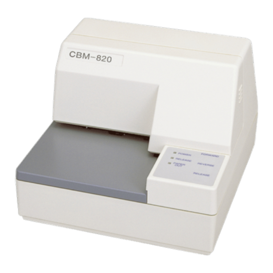
3. Outer Appearance and Component Parts 3.1 General guide The following illustrations describe the major components, buttons, and connectors of your printer. Printer cover Protects internal components. Control panel Three indicators show the printer status, and two switches provide control over printer functions. -
Seite 24: Operation
4. Operation 4.1 Removing the printer cover ❏ Push straight up on the ridged locations on the sides of the printer cover to remove it from the printer. ❏ To replace the cover, slide it back down into position. Gently press down on the cover until you hear it click securely into place. - Seite 25 ❏ Remove the ribbon cassette from its packaging, and turn its knob in the direction indicated by the arrow to take up any slack in the ribbon. ❏ Holding the ribbon cassette so that the ribbon is facing down, install the cassette into the slip printer as shown in the illustration.
-
Seite 26: Removing The Ribbon Cassette
4.3 Removing the ribbon cassette Use the following procedure to remove the ribbon cassette from the slip printer when you want to replace it with a new one. ❏ Make sure that the printer is turned off and unplugged from its power outlet. - Seite 27 ❏ Plug the other end of the power cord to a standard household wall outlet. ❏ Use the power switch on the left side of the printer to turn power on and off. Important! We recommend that you unplug the printer from the power outlet whenever you do not plan to use it for long periods.
-
Seite 28: Connecting To Your Host Computer
4.5 Connecting to your host computer The computer sends data to the printer through a cable to the printer’s standard serial interface (Connector Type: D-sub 25-pin). This printer does not come with a cable, so it is up to you to obtain one that suits your needs. Important! •... - Seite 29 Pass the fastener through the ferrite core. 5 cm maximum Fastner Loop the fastener around the cable and lock it. Use scissors to cut off any excess. Pull and cut ❏ Plug one end of the serial cable into the serial port of your computer, and the other end of the cable into the socket on the back of the printer.
-
Seite 30: Connecting To A Peripheral Unit
4.6 Connecting to a peripheral unit You can connect a peripheral unit to the printer using a modular plug. The following describes how to install the ferrite core and make the actual connection. See “Modular plug” on page 31 for details about the type of modular plug that is required. -
Seite 31: Inserting The Paper Into The Printer
Loop the fastener around the cable and lock it. Use scissors to cut off any excess. Pull and cut ❏ Plug one end of the modular cable into the modular jack of the peripheral. ❏ Remove the modular jack cover from the back of the printer and plug the other end of the modular cable into the jack of the printer. -
Seite 32: Autoside Loading
❏ Place a piece of the paper onto the printer’s document table and slide its right edge into the printer. Printing will be performed on the side of the paper that is facing up (the one you can see), starting from the top of the paper. - Seite 33 ❏ Push the right edge of the paper into the printer until it stops. At that time, the PAPER OUT indicator will go out, and the printer mechanism will automatically align the paper for printing from the top. ❏ Send data from your host computer to be printed on the paper. ❏...
-
Seite 34: Control Panel Operations
4.9 Control Panel Operations The control panel gives you some push-button control over the slip printer operation. It also includes indicator lights, which tell you the current status of the printer at a glance. FORWARD POWER RELEASE PAPER REVERSE RELEASE 4.9.1 Indicator lights The following table describes the meaning of indicator lights when it is on, off, or flashing. -
Seite 35: Producing A Test Print
4.9.3 Producing a test print The following procedure can be used at any time to test the printer. ❏ Turn on the printer and insert a piece of paper (page 11, 16). ❏ Turn off printer power. ❏ While holding down RELEASE, turn printer back on. Keep RELEASE depressed for a few moments until the printer beeps and the printer test print starts. - Seite 36 This is caused when mechanical parts of the printer get out of alignment. This happens only rarely and you may never experience it at all throughout the life of the printer. If you do have problems, use the following procedure to correct it. ❏...
-
Seite 37: Hexadecimal Dump
The dots alignment adjustment setting you selected is stored in printer memory and a pattern is printed using the selected setting followed by the message “Adjust Complete!” The printer ejects the paper after printing is complete. Note: You setting is not registered if you turn off printer power before pressing REVERSE to exit the Dot Alignment Adjust Mode. -
Seite 38: Errors
4.9.6 Errors There are three types of errors: recoverable errors that require some action by you before they clear, non-recoverable errors that require servicing by an authorized service provider, and a data receive error. Errors are indicated by and audible buzzer and the indicators. (1) Recoverable Errors Indicators Error Type... -
Seite 39: Paper Sensors
4.10 Paper Sensors The following paper sensors are available. ❏ TOF Sensor This top-of-form sensor detects the leading edge of the paper. When enabled, the TOF sensor detects when there is no paper present and stops printing. ❏ BOF Sensor This bottom-of-form sensor detects the trailing edge of the paper. -
Seite 40: Making Dip Switch Settings
5. Making DIP Switch Settings The printer’s DIP switches let you specify communications parameters, receive buffer size, and emulation. This “5. Making DIP Switch Settings” explains the settings you can make and tells you how to actually change DIP switch settings. 5.1 Accessing the DIP switches The DIP switches are located inside the printer, underneath the document table. - Seite 41 It is not necessary to remove the document table completely, just move it enough so you can get at the DIP switches inside. Note: If the document table seems to be getting caught on the rollers, it means that you are not pressing down at point (a) enough. Pressing at point (a) should separate the rollers to the document table can slide freely.
-
Seite 42: Available Dip Switch Settings
5.2 Available DIP switch settings The following table shows all the possible settings for the DIP switch. The factory default settings are ON for switches 1 through 7 and OFF for switches 8 through 10. Switch Parameter Baud Rate See table below Data Length 8 bits 7 bits... -
Seite 43: Memory Switch Settings
5.3 Memory Switch Settings Each memory switch is a 16-bit word store in EEPROM. For details on the functions and settings of memory switches, see the “9. Print Control Functions (ESC#)”. The table below shows the factory settings for the memory switches. Memory Switch Hexadecimal Code –... -
Seite 44: Interface
6. Interface This appendix provides detailed specifications for the printer’s standard serial interface. 6.1 Pins and Signal Names Signal Direction Function Name — Frame ground Transmission data Receive data Same as DTR signal N.C. Not connected • DIP Switch 9 = OFF In DTR/DSR communication mode when Memory Switch4-5 = 0, indicates whether data receive from host is enabled or disabled. -
Seite 45: Interface Connections
Signal Direction Function Name Indicates whether data receive from host is enabled or disabled. DTR/DSR Communication Mode Space when receive is enabled. X-On/X-Off Communication Mode Always space, except during following conditions: • Period between reset and communication enabled • During self-test printing and dot alignment adjustment 21 - 24 N.C. -
Seite 46: Peripheral Unit Driver Circuit
7. Peripheral Unit Driver Circuit This printer is equipped with a circuit for driving peripheral units, such as cash drawers. A 6-pin modular connector for connection of the peripheral unit is located on the back of the printer. To connect to the drive circuit, connect the peripheral unit to the modular connector using a cable supplied by you like that one shown in the figure below. -
Seite 47: Drive Circuit
7.2 Drive circuit The recommended drive unit is shown below. Drive output: 24V, 1.0A max. With shield Peripheral unit 1 +24V 7824 M-GND 4.7kΩ 1/4W M-GND Peripheral unit 2 Compulsion switch Frame ground Printer side User side Notes • Peripheral Units 1 and 2 cannot be driven simultaneously. •... -
Seite 48: Maintenance And Service
8. Maintenance and Service For the information on maintenance and service, please contact our dealer. – 33 –... -
Seite 49: Print Control Functions
9. Print Control Functions This printer supports one command mode: the ESC/POS mode. The ESC/POS mode emulates the Epson TM-295 slip printer. This chapter provides you with all of the commands supported by this printer. 9.1 List of ESC/POS Commands Standard Page Command... - Seite 50 Standard Page Command Function Code Page Mode Mode ESC W Sets Print Area in Page Mode 1BH 57H (Set) ESC c4 Selects No-paper Sensor Valid for Print Stop 1BH 63H 34H n ESC c5 Enables/Disables Panel Switch 1BH 63H 35H n ESC d Print and N-line Paper Feed 1BH 64H n...
-
Seite 51: Command Details
9.2 Command Details 9.2.1 Description of Each Items XXXX [Function] Shows a command function. [Code] Shows a sequence of code consisting the command; ASCII represents the ASCII code and [ ]k a repeat count of k-times. [Range] Shows a settable range of an argument. [Outline] Outlines the command. -
Seite 52: Command Details
9.2.2 Command Details [Function] Horizontal Tab [Code] ASCII Hexadecimal Decimal [Outline] This command shifts a printing position to the next horizontal tab position. [Caution] • The horizontal tab position is set by ESC D. • The command is ignored if the next horizontal tab position has not been set. •... - Seite 53 [Function] Prints and Ejects Single Sheet, and Prints and Returns in Paper Mode [Code] ASCII Hexadecimal Decimal There is the following difference between the standard mode and page mode: <Standard Mode> [Outline] This command prints the data in the print buffer and ejects a single sheet. [Caution] •...
- Seite 54 DLE EOT n [Function] Sends Status at Real Time [Code] ASCII DLE EOT n Hexadecimal Decimal [Range] 3, n = 5 [Outline] This command sends the n-specified status at real time. Description Sends the printer status. Sends the off-line factor status. Sends the error factor status.
- Seite 55 n = 1: Printer status Description Hexadecimal Decimal Unused Unused Status of the drawer kick connector No. 3 pin = L Status of the drawer kick connector No. 3 pin = H On-line status Off-line status Unused Undefined – – Undefined –...
- Seite 56 n = 3: Error factor status Description Hexadecimal Decimal Unused Unused Undefined – – Undefined – – Unused No irrecoverable error Irrecoverable error Undefined – – Unused n = 5: Slip status Description Hexadecimal Decimal Unused Unused The slip has been selected Slip insertion non-waiting status Slip insertion waiting status Unused...
- Seite 57 [Function] Cancels Print Data in Page Mode [Code] ASCII Hexadecimal Decimal [Outline] This command erases all the print data in the current print area in the page mode. [Caution] • This command is valid only in the page mode. • Even the print data in the previously set print area is erased, if it is extended over the currently set print area.
- Seite 58 ESC ! n [Function] Selects Print Mode in Batch [Code] ASCII ESC ! Hexadecimal Decimal [Range] [Outline] This command specifies the print mode. Each bit has the following meaning. Description Hexadecimal Decimal Character font 5 × 7 Character font 7 × 7 Undefined –...
- Seite 59 ESC # [Function] Sets Memory Switch [Code] ASCII <ESC>"#N, n1 n2 n3 n4" <LF> <NUL> Hexadecimal 1B 23 N 2C n1 n2 n3 n4 0A 00 Decimal 27 35 N 44 n1 n2 n3 n4 10 0 N : Memory switch segment number (4 and 5 only) n1 n2 n3 n4: Set data [Range] N="4"(34h) or "5"(35h)
- Seite 60 Memory Switch 5 (MSW5) The setting upon shipment from the factory is indicated with “ ”. Description 0 0 0 0 1 1 1 1 <ESC> "q" command function See Table below (LSB) <ESC> "q" command function See Table below (LSB) (LSB) Automatic clamp function...
- Seite 61 ESC % n [Function] Selects/Deselects Download Character Set [Code] ASCII ESC % Hexadecimal Decimal [Range] [Outline] This command selects or deselects the download character set. n is valid only for the least significant bit. • At n = < 0>B, the command deselects the download character set(selects an internal character set).
- Seite 62 ESC & y c1 c2 [x[d]yxx]c2-c1+1 [Function] Defines Download Characters [x [d] y × x ] c2-c1+1 [Code] ASCII ESC & [x [d] y × x ] c2-c1+1 Hexadecimal [x [d] y × x ] c2-c1+1 Decimal [Range] y = 1 6 (When the 5 ×...
- Seite 63 [Example] • When selecting the 5 × 7 font p1 p2 p3 p4 p5 p6 When defining the pattern above to the code 20H & Code (hex.) • When selecting the 7 × 7 font p1 p2 p3 p4 p5 p6 p7 p8 p9 p10 When defining the pattern above to the code 20H &...
- Seite 64 ESC * m nL nH [d]k [Function] Selects Bit Image Mode [Code] ASCII ESC * [d] k Hexadecimal [d] k Decimal [d] k [Range] m = 0, 1 nH × 256 k = nL [Outline] • This command specifies the bit image of the m-mode as to the number of dots specified with nL and nH.
- Seite 65 • The following shows the relations between the bit image data and the dots printed. 7 6 5 4 3 2 1 0 Bit Image Data High Print Data – 50 –...
- Seite 66 ESC 2 [Function] Sets 1/6-inch Line Feed [Code] ASCII ESC 2 Hexadecimal Decimal [Outline] This command sets a line feed amount per line to 1/6 inch. [Caution] There are two kinds of line feed amounts for the standard mode and page mode. •...
- Seite 67 ESC = n [Function] Selects Peripheral Device [Code] ASCII ESC = Hexadecimal Decimal [Range] [Outline] This command selects a peripheral device which validates the subsequent data, depending on a value of n. • Each bit has the following different meanings. •...
- Seite 68 ESC @ Fnction] Initializes Printer [Code] ASCII ESC @ Hexadecimal Decimal [Outline] This command clears the data in the print buffer to initialize various settings. [Caution] • The setting of the DIP switch is not re-read. • The data in the reception buffer is not cleared. ESC C n [Function] Sets Single Sheet Ejection Length...
- Seite 69 ESC D [n]k NUL [Function] Sets Horizontal Tab Position [Code] ASCII ESC D [n] k NUL Hexadecimal [n] k 00 Decimal [n] k [Range] [Outline] This command sets a horizontal tab position. • n denotes the number of columns from the head of the line to the horizontal tab setting position.
- Seite 70 ESC F n [Function] Selects/Deselects Ejection of Single Sheet in Reverse Direction [Code] ASCII ESC F Hexadecimal Decimal [Range] [Outline] This command selects or deselects single sheet ejection in the reverse direction with FF. • n is valid only for the least significant bit. At n = <...
- Seite 71 ESC K n [Function] Print and Reverse Paper Feed [Code] ASCII ESC K Hexadecimal Decimal [Range] [Outline] This command prints the data in the print buffer and feeds the paper by n/60 inch in the reverse direction. Since the printer has the minimum paper feed pitch of 1/144 inch, n/60-inch reverse directional paper feed is treated as follows: •...
- Seite 72 ESC L [Function] Selects Page Mode [Code] ASCII ESC L Hexadecimal Decimal [Outline] This command switches from the standard mode to the page mode. • The page mode deploys the received data over the specified print area and prints it in batch with the FF command.
- Seite 73 ESC R n [Function] Selects International Characters [Code] ASCII ESC R Hexadecimal Decimal [Range] [Outline] This command selects the character sets for the countries listed below, depending on a value of n. Character Set U.S.A France Germany England Denmark I Sweden Italy Spain...
- Seite 74 ESC T n [Function] Selects Character Print Direction in Page Mode [Code] ASCII ESC T Hexadecimal Decimal [Range] 3, 48 [Outline] This command specifies the character printing direction and start point in the page mode. The character printing direction is specified with n. n = 0, 48 : →...
- Seite 75 ESC W xL xH yL yH dxL dxH dyL dyH [Function] Sets Print Area in Page Mode [Code] ASCII ESC W dxH dyL Hexadecimal dxH dyL Decimal dxH dyL [Range] 255, xH = 0, 0 255, 0 1, 0 255, dxH = 0 255, 0 1 (Except dxL = dxH = 0 or dyL = dyH = 0) [Outline]...
- Seite 76 ESC c 4 n [Function] Selects No-paper Sensor Valid for Print Stop [Code] ASCII ESC c Hexadecimal Decimal [Range] [Outline] • This command selects in which status of the no-paper Sensor printing should be stopped. Each bit has the following different meanings. Sensor Hexadecimal Decimal...
- Seite 77 ESC c 5 n [Function] Enables/Disables Panel Switch [Code] ASCII ESC c Hexadecimal Decimal [Range] [Outline] This command enables/disables the panel switch. • n is valid only for the least significant bit. At n = < 0>B, the command enables the panel switch. At n = <...
- Seite 78 ESC e n [Function] Print and N-line Reverse Paper Feed [Code] ASCII ESC e Hexadecima l Decimal [Range] [Outline] This command prints the data in the print buffer and feeds the paper by n-lines in the reverse direction. [Caution] • This command is valid only in the standard mode. •...
- Seite 79 ESC p m t1 t2 [Function] Generates Specified Pulses [Code] ASCII ESC p Hexadecimal Decimal [Range] m = 0, 1, 48, 49 [Outline] This command outputs the signal specified with t1 or t2 to the connector pin m. • The following table lists the types of m. Connector Pin 0, 48 Drawer kick connector No.
- Seite 80 ESC q [Function] Release [Code] ASCII ESC q Hexadecimal Decimal [Outline] This command executes a release. The function can be selected with the Memory switch. Memory Switch Description 4–D 4–C Executes a release. Executes a release after ejecting all the paper in the forward direction(far side).
- Seite 81 ESC "t" n [Function] Selects Character Code Table [Code] ASCII ESC t Hexadecimal Decimal [Range] [Outline] This command selects Page-n in the Character Code List.. Character Type Codepage PC437 (USA, European Standard) Codepage Katakana (Japanese) Codepage PC850 (Multilingual) Codepage PC860 (Portuguese) Codepage PC863 (Canadian-French) Codepage PC865 (Nordic) Codepage PC852 (Eastern Europe)
- Seite 82 ESC u n [Function] Sends Peripheral Device Status [Code] ASCII ESC u Hexadecimal Decimal [Range] n = 0, 48 [Outline] This command sends the status of the connector pin n every time the command is executed. The following lists the type of n. Connector Pin 0, 48 Drawer kick connector No.
- Seite 83 ESC v [Function] Sends Paper Sensor Status [Code] ASCII ESC v Hexadecimal Decimal [Outline] This command sends the status of the paper sensor when it is executed. [Caution] The following table describes the status sent. • If DTR/DSR control is selected and the memory switch 4-5 is set to 0, the printer sends only 1 byte after confirming that the host is ready to receive (the DSR signal status is Space).
- Seite 84 ESC { n [Function] Selects/Deselects Inverted Print [Code] ASCII ESC { Hexadecimal Decimal [Range] [Outline] This command selects or deselects inverted print. • n is valid only for the least significant bit. At n = < 0>B, the command deselects inverted print. At n = <...
- Seite 85 This command sends the printer ID listed in the table below, depending on setting of n, when it is executed. Type of Printer ID Specification ID (Hex.) 1, 49 Model ID CBM-820 2, 50 Type ID See Table below 3, 51 ROM version Depends on ROM version [Caution] •...
- Seite 86 GS a n [Function] Enables/Disables Automatic Status Sending [Code] ASCII Hexadecimal Decimal [Range] [Outline] This command selects which status should be the target of automatic status sending (ASB: Automatic Status Back). Each bit has the following different meanings. ASB Target Status Hexadecimal Decimal Drawer kick connector No.
- Seite 87 1st Byte (Printer Information) Status Hexadecimal Decimal Unused Unused Drawer kick connector No. 3 pin status = L Drawer kick connector No. 3 pin status = H On-line status Off-line status Unused Unused Not feeding the paper by the Paper Feed switch Feeding the paper by the Paper Feed switch Unused 2nd Byte (Error Information)
- Seite 88 4th Byte (Paper Sensor Information) Status Hexadecimal Decimal Slip selected Slip printable Slip unprintable Undefined – – Undefined – – Unused Undefined – – Undefined – – Unused [Default] Bit 1: • "0" (printable) when the slip is inserted, and "1" (unprintable) when ejection starts. •...
- Seite 89 GS r n [Function] Sends Status [Code] ASCII Hexadecimal Decimal [Range] 2, 49 [Outline] This command sends the status, depending on setting of n. Description 1, 49 Sends the paper sensor status. (Same as ESC v) 2, 50 Sends the status of the drawer kick connector. (Same as ESC u 0) •...
- Seite 90 n = 2, 50 : Drawer kick connector status Status Hexadecimal Decimal Drawer kick connector No. 3 pin status = L Drawer kick connector No. 3 pin status = H Undefined – – Undefined – – Undefined – – Unused undefined –...
-
Seite 91: Character Codes Table
10. Character Codes Table 10.1 Codepage PC437 (USA, European Standard) – 76 –... -
Seite 92: Codepage Katakana (Japanese)
10.2 Codepage Katakana (Japanese) – 77 –... -
Seite 93: Codepage Pc850 (Multilingual)
10.3 Codepage PC850 (Multilingual) – 78 –... -
Seite 94: Codepage Pc860 (Portuguese)
10.4 Codepage PC860 (Portuguese) – 79 –... -
Seite 95: Codepage Pc863 (Canadian-French)
10.5 Codepage PC863 (Canadian-French) – 80 –... -
Seite 96: Codepage Pc865 (Nordic)
10.6 Codepage PC865 (Nordic) – 81 –... -
Seite 97: Codepage Pc852 (Eastern Europe)
10.7 Codepage PC852 (Eastern Europe) – 82 –... -
Seite 98: Codepage Pc866 (Russian)
10.8 Codepage PC866 (Russian) – 83 –... -
Seite 99: Codepage Pc857 (Turkish)
10.9 Codepage PC857 (Turkish) – 84 –... -
Seite 100: Windows Codepage
10.10 Windows Codepage – 85 –... -
Seite 101: Codepage Pc858 (Multilingual+Euro)
10.11 Codepage PC858 (Multilingual+Euro) – 86 –... -
Seite 102: Appendix 1: Outline Drawing Of Printer (Cbm-820)
Appendix 1: Outline Drawing of Printer (CBM-820) Dimensions and Weight 180 (W) × 190 (D) × 138 (H) mm / 7.09 ″ × 7.48 ″ × 5.43 ″ Dimensions Weight 2.1 kg / 4.6 lbs. 180 mm (7.09”) 190 mm (7.48”) -
Seite 103: Appendix 2: Outline Drawing Of Ac Adapter (31Ad)
Appendix 2: Outline Drawing of AC Adapter (31AD) Dimensions and Weight 70 (W) × 130 (D) × 40 (H) mm / 2.76 ″ × 5.12 ″ × 1.58 ″ Dimensions Weight 0.43 kg / 0.94 lbs. AC ADAPTER Unit: mm –... -
Seite 104: German
<<< German >>>... - Seite 105 < VORSICHT > 1. Bitte lesen Sie die Bedienungsanleitung vor dem Betrieb des Geräts aufmerksam durch und bewahren Sie die Anleitung anschließend für späteres Nachschlagen an einem sicheren Platz auf. 2. Änderungen des Inhalts dieser Anleitung bleiben ohne Vorankündigung vorbehalten. 3.
-
Seite 106: Zu Beachtende Sicherheitsmassregeln
ZU BEACHTENDE SICHERHEITSMASSREGELN Zur Vermeidung von Gefahren gegenüber dem Bediener und anderen Personen und Sachschäden sind die folgenden Vorsichtsmaßregeln unbedingt zu beachten. G Der folgende Text beschreibt das Ausmaß der Gefahren und potentiellen Sachschäden, die durch eine Mißachtung der Bedienungshinweise oder durch die unsachgemäße Handhabung des Geräts entstehen können. - Seite 107 WARNUNG G Beim Betrieb des Geräts sind die nachfolgenden Vorsichtsmaßregeln unbedingt zu beachten. Eine Mißachtung dieser Hinweise kann zu Schäden, Funktionsstörungen, Rauchentwicklung und Brandgefahr durch Überhitzen und zu elektrischen Schlägen führen. Der fortgesetzte Betrieb des Geräts in anormalem Zustand, wie z.B. nach einer Beschädigung, kann Funktionsstörungen, Rauchentwicklung, fremde Gerüche/Geräusche und Brände verursachen.
-
Seite 108: Vorsichtsmassregeln Für Die Aufstellung
VORSICHTSMASSREGELN FÜR DIE AUFSTELLUNG • Das Gerät nicht an Plätzen abstellen oder betreiben, an denen es Feuer, Feuchtigkeit oder direkter Sonnenbestrahlung ausgesetzt ist. Ebenso sind Plätze in der Nähe von Heizkörpern und sonstigen Wärmenquellen zu vermeiden, an denen Umgebungstemperatur und Luftfeuchtigkeit nicht den vorgeschriebenen Betriebsbedingungen entsprechen, sowie Plätze, an denen das Gerät Öl, Metallspänen oder Staub ausgesetzt ist. -
Seite 109: Vorsichtsmassregeln Für Die Handhabung
VORSICHTSMASSREGELN FÜR DIE HANDHABUNG Zur Vermeidung von Problemen sind bei der Handhabung des Geräts die folgenden Vorsichtsmaßregeln zu beachten. • Keine andere Betriebsstromquelle als das mitgelieferte Netzteil verwenden. Das Netzteil nicht für andere Zwecke verwenden. • Nicht ohne eingelegte Papier drucken. •... -
Seite 110: Tägliche Wartung
TÄGLICHE WARTUNG • Bei der Wartung immer den Netzschalter des Druckers auf Aus stellen und den Stecker aus der Steckdose ziehen. • Schmutz und Staub mit einem trockenen, weichen Tuch vom Druckergehäuse abwischen. Bei starker Verschmutzung einen Lappen in Wasser anfeuchten, auswringen und damit abwischen. Hierzu niemals flüchtige organische Lösungsmittel, wie z.B. -
Seite 111: Drucker-Einrichtung
1. Drucker-Einrichtung Dieses Kapitel enthält wichtige Informationen zur Vorbereitung Ihres Druckers. Bitte dieses Kapitel sorgfältig durchlesen, bevor Sie den Drucker zum ersten Mal in Betrieb nehmen. In diesem Kapitel erfahren Sie Einzelheiten über: ❏ Wahl eines Aufstellungsorts für den Drucker ❏... -
Seite 112: Auspacken Des Druckers
1.2 Auspacken des Druckers Überprüfen Sie den Kartoninhalt, und vergewissern Sie sich, daß alle unten abgebildeten Teile vorhanden sind. Farbbandkasset Drucker Bedienungsanleitung Ferritkern Kabelbinder Netzkabel Netzteil Hinweise zum Netzteil Hinweis: Das Netzteil wird von Hinweisen begleitet. Bitte dieses Dokument vor der Verwendung des Netzteils durchlesen, und zusammen mit dieser Anleitung aufbewahren. -
Seite 113: Entfernen Der Schutzmaterialien
1.3 Entfernen der Schutzmaterialien Schutzstreifen und ein Stück Pappe sind im Drucker eingelegt, um die internen Bauteile beim Transport zu schützen. Vor der Inbetriebnahme des Druckers müssen die in der Abbildung markierten Schutzmaterialien entfernt werden. Klebeband Klebeband – 98 –... -
Seite 114: Technische Daten
2. Technische Daten 2.1 Allgemeine Daten Drucksystem Serieller Nadeldruck Anzahl der Druckkopfnadeln 9 Stifte Druckgeschwindigkeit Maximal 3,1 Zeilen/s Anzahl der Druckspalten Gesamt-Punkte Druckbreite 63 mm Punktabstand Horizontal: 0,30 mm Vertikal: 0,35 mm Papierbreite 80 mm bis 182 mm Sensoren Sensor für Papier verbraucht, obere Papierkante, untere Papierkante Befehlsmodi ESC/POS-Modus... -
Seite 115: Druckspezifikationen
2.2 Druckspezifikationen Zeichensatz Codepage PC437 (USA, European Standard) Codepage Katakana (Japanese) Codepage PC850 (Multilingual) Codepage PC860 (Portuguese) Codepage PC863 (Canadian-French) Codepage PC865 (Nordic) Codepage PC852 (Eastern Europe) Codepage PC866 (Russian) Codepage PC857 (Turkish) Windows Codepage Codepage PC858 (Multilingual+Euro) 7 × 9 (halb), 42 Spalten Zeichenmatrix 5 ×... - Seite 116 Blattanschlag (fixiert) Oberer Papierkantensensor (fixiert) Papier Kopf Nr. 1 62,7 Erste Druckzeile Letzte Druckzeile KopfNr. 9 Papiervorsc hubwalze Unterer Papierkantensensor (fixiert) Einheit: mm Print Position 8 mm Keine Löcher in diesem Bereich Kein Papier mit Löchern in diesem Bereich verwenden. Löcher im Papier können Fehlfunktionen des Papiersensors verursachen.
-
Seite 117: Technische Daten Zur Netzversorgung
2.4 Technische Daten zur Netzversorgung Netzversorgung Netzteil 31AD, Schalttyp Eingang 100 bis 240 V Netzspannung, 50/60 Hz Ausgang DC 24V Gleichspannung ±5%, 1,9 A Stecker TCP8927-83-1100 (Hersteller: HOSHIDEN, oder gleichwertiges Teil) Leistungsaufnahme Bedingungen: DC 24 V, Antrieb für externe Geräte nicht eingeschlossen Betrieb Fortlaufender ASCII-Druck +Papiervorschub: 0,6 A (Durchschnittswerte) -
Seite 118: Außenansicht Und Bauteile
3. Außenansicht und Bauteile 3.1 Allgemeine Anleitung Die folgenden Abbildungen zeigen die Hauptbauteile des Druckers. Druckerabdeckung Schützt interne Bauteile. Bedienfeld Drei Anzeigen zeigen den Druckerzustand, und zwei Schalter erlauben Steuerung von Druckerfunktionen. Netzschalter Zum Ein- und Ausschalten Dokumentenauflage des Druckers. Stützt das Quittungspapier, das in den Quittungsdrucker eingeschoben wird. -
Seite 119: Betrieb
4. Betrieb 4.1 Abnehmen der Druckerabdeckung ❏ Die geriffelten Teile an den Druckerseiten gerade nach oben drücken, um die Abdeckung abzunehmen. ❏ Zum Schließen die Abdeckung wieder nach unten aufsetzen. Vorsichtig aufdrücken, bis sie hörbar einrastet. 4.2 Einsetzen der Farbbandkassette ❏... - Seite 120 ❏ Die Farbbandkassette aus der Verpackung nehmen, und den Knopf auf der Farbbandkassette im Uhrzeigersinn drehen, um eventuell vorhandene Bandschlaufen aufzuwickeln. ❏ Die Farbbandkassette so halten, daß das Farbband nach unten weist und die Kassette in den Drucker einsetzen, wie in der Abbildung gezeigt. ❏...
-
Seite 121: Entnehmen Der Farbbandkassette
4.3 Entnehmen der Farbbandkassette Folgendermaßen verfahren, um die Farbbandkassette zum Austausch aus dem Drucker zu nehmen. ❏ Sicherstellen, daß der Drucker ausgeschaltet und von der Betriebsstromversorgung getrennt ist. ❏ Die Druckerabdeckung abnehmen. ❏ Die Farbbandkassette wie in der Abbildung gezeigt greifen und vorsichtig aus dem Druckmechanismus ziehen. - Seite 122 ❏ Den anderen Stecker des Netzkabels an eine Netzsteckdose anschließen. ❏ Den Netzschalter an der linken Seite des Druckers zum Ein- und Ausschalten verwenden. Wichtig! Wir empfehlen, den Netzstecker aus der Steckdose zu ziehen, wenn der Drucker längere Zeit lang nicht benutzt werden soll. Der Drucker sollte vorzugsweise an einem Platz aufgestellt werden, der leichten Zugang zur Netzsteckdose gewährt.
-
Seite 123: Anschließen An Den Hostcomputer
4.5 Anschließen an den Hostcomputer Die Datenübertragung vom Computer zum Drucker erfolgt über ein Kabel zur seriellen Schnittstellenbuchse des Druckers (Buchse: D-sub 25polig). Das Kabel ist im Lieferumfang dieses Druckers nicht enthalten und muß getrennt gekauft werden. Wichtig! • Die folgende Anleitung bezieht sich auf das mit IBM-kompatiblen Personalcomputern verwendete Schnittstellenkabel. - Seite 124 Führen Sie den Kabelbinder durch den Ferritkern. Maximum 5 cm Kabelbinder Führen Sie den Kabelbinder um das Kabel und sperren Sie ihn. Schneiden Sie überschüssiges Band mit einer Schere ab. Ziehen und abschneiden ❏ Ein Ende des Kabels an den seriellen Anschluß des Computers anschließen und das andere Ende an die Buchse an der Rückseite des Druckers an.
-
Seite 125: Anschluß An Ein Peripheriegerät
4.6 Anschluß an ein Peripheriegerät Es kann ein Peripheriegerät an den Drucker mit einem Modularstecker angeschlossen werden. Im folgenden wird beschrieben, wie der Ferritkern angebracht und die Verbindung hergestellt wird. “Modularstecker” auf Seite 126 für den Typ von Modularstecker, der dazu erforderlich ist. Beachten Sie, daß... -
Seite 126: Papier In Den Drucker Einlegen
Das Befestigungsband um das Kabel wickeln und sperren. Schneiden Sie überschüssiges Band mit einer Schere ab. Ziehen und abschneiden ❏ Einen Stecker des Modularkabels in die Modularbuchse am Peripheriegerät stecken. ❏ Die Modularbuchsenabdeckung von der Rückseite des Druckers abnehmen, und den anderen Stecker des Modularkabels in die Modularbuchse am Drucker stecken. -
Seite 127: Automatischer Papiereinzug (Autoside Loading™)
❏ Legen Sie ein Blatt Papier auf den Dokumententisch des Druckers und schieben Sie die rechte Ecke in den Drucker. Der Ausdruck erfolgt auf der Seite, die nach oben zeigt (die Seite, die Sie sehen können) und beginnt am oberen Rand des Blattes. Wichtig! Benutzen Sie kein verknicktes oder verwelltes Papier. - Seite 128 ❏ Schieben Sie die rechte Ecke des Blattes in den Drucker, bis Sie einen Widerstand spüren. Zu diesem Zeitpunkt wird die Anzeige PAPER OUT ausgehen und der Druckermechanismus zieht das Blatt automatisch ein und richtet es an der Druckstartposition aus. ❏...
-
Seite 129: Bedienfeld
4.9 Bedienfeld Das Bedienungsfeld enthält einige Tasten, mit deren Hilfe Sie den Drucker bedienen künnen. Es enthält auch einige LED-Anzeigen, die Sie über den aktuellen Status des Druckers informieren. FORWARD POWER RELEASE PAPER REVERSE RELEASE 4.9.1 Anzeigeleuchten Die folgende Tabelle stellt die Bedeutung des Leuchtens, Nichtleuchtens oder Blinkens der Anzeigeleuchten dar. -
Seite 130: Tasten
4.9.2 Tasten Die folgende Tabelle stellt die Funktion der drei Steuertasten am Bedienfeld dar. Taste Beschreibung Drücken, um das Quittungspapier zur Rückseite des Druckers FORWARD zuzuführen. Ein Tastendruck schiebt um eine Zeile vor, Gedrückthalten schiebt kontinuierlich vor. Drücken , um das Quittungspapier zur Vorderseite des Druckers REVERSE zurückzuführen. - Seite 131 Der Grund dafür ist, daß mechanische Teile des Druckers gegeneinander verschoben werden. Dies geschieht nur selten, und die meisten Anwender werden während der Lebensdauer des Druckers damit nicht konfrontiert werden. Falls aber dieses Problem auftritt, kann es auf folgende Weise behoben werden.
-
Seite 132: Sedezimaler Datenausdruck
Die Einstellungen für die Punktausrichtung werden im Druckerspeicher gespeichert, und ein Muster wird mit der gewählten Einstellung ausgedruckt, gefolgt von der Meldung “Adjust Complete!”. Der Drucker gibt das Papier nach dem Druckvorgang aus. Hinweis: Wenn der Drucker ausgeschaltet wird, ohne die Taste REVERSE zum Verlassen des Punkteinstellmodus zu drücken, werden die Einstellungen nicht gespeichert. -
Seite 133: Nicht Behebbare Fehler
4.9.6 Fehler Es gibt drei Typen von Fehlern: behebbare Fehler, die zum Beheben eine Maßnahme von Seiten des Anwenders erfordern, und nicht behebbare Fehler, die Wartungsmaßnahmen durch den Kundendienst erfordern, und Datenempfangsfehler. Die Fehlertypen werden durch ein Tonsignal und die Anzeigen dargestellt. -
Seite 134: Papiersensoren
4.10 Papiersensoren Die folgenden Papiersensoren stehen zur Verfügung. ❏ TOF-Sensor Dieser Vorderkantensensor ("top of form") erkennt die Papiervorderkante. Wenn er aktiviert ist, erkennt der TOF-Sensor, daß kein Papier vorhanden ist und stoppt den Druckvorgang. ❏ BOF-Sensor Dieser Hinterkantensensor ("bottom of form") erkennt die Hinterkante des Papiers. -
Seite 135: Dip-Schaltereinstellung
5. DIP-Schaltereinstellung Die DIP-Schalter des Druckers dienen zum Einstellen der Datenaustausch- parameter, Der Abschnitt“5. DIP-Schaltereinstellung” erkärt die Einstellungen, die Sie vornehmen können und beschreibt, wie DIP-Schalter umgestellt werden. 5.1 Zugang zu den DIP-Schaltern Die DIP-Schalter befinden sich im Drucker unter der Papierauflage. Für Zugang zu den DIP-Schaltern ist die Papierauflage wie folgt zu verschieben. - Seite 136 Die Papierauflage braucht hierzu nicht vollständig entfernt zu werden. Er genügt die Auflage soweit zur Seite zu schieben, bis die DIP-Schalter zugänglich sind. Hinweis: Falls die Papierauflage durch die Walzen festgehalten wird, bedeutet dies, daß nicht stark genug auf Punkt (a) gedrückt wird. Durch ausreichenden Druck auf Punkt (a) lösen sich die Walzen von der Papierablage, wonach sich die Ablage ungehindert verschieben läßt.
-
Seite 137: Verwendbare Dip-Schaltereinstellungen
5.2 Verwendbare DIP-Schaltereinstellungen Die folgende Tabelle zeigt alle möglichen DIP-Schaltereinstellungen. Die Schalter 1 bis 7 sind werksseitig auf ON gestellt, während die Schalter 8 bis 10 werksseitig auf OFF gestellt sind. Schalter Parameter Baudrate Siehe untenstehende Tabelle Datenlänge 8 bits 7 bits Paritätsprüfung Inaktiv... -
Seite 138: Einstellen Der Speicherschalter
5.3 Einstellen der Speicherschalter Jeder Speicherschalter ist ein 16-Bit-Wortspeicher in EEPROM. Einzelheiten über Funktionen und Einstellungen der Speicherschalter siehe “9. Print Control Functions (ESC#)”. Die untenstehende Tabelle zeigt die werksseitigen Einstellungen der Speicherschalter. Speicherschalter Hexadezimalcode – – – – 0000 0000 Wichtig! Ein Umstellen der Speicherschalter kann zu Funktionsstörungen des Druckers... -
Seite 139: Schnittstelle
6. Schnittstelle Dieser Anhang enthält detaillierte Spezifikationen für die Standardeinstellung der Druckerschnittstelle. 6.1 Stifte und Signalnamen Stift- Signal Richtung Funktion name – Gehäuseerdung Übertragungsdaten Empfangsdaten ESC/POS-Modus Identisch mit DTR-Signal N.C. Nicht angeschlossen • DIP-Schalter 9 = OFF Speicherschalter 4-5 im DTR/DSR-Datenaustauschmodus = 0 zeigt an, ob der Datenempfang vom Hauptrechner aktiv oder inaktiv ist. -
Seite 140: Schnittstellenanschlüsse
Stift- Signal Richtung Funktion name Zeigt an, ob der Datenempfang vom Hauptrechner aktiv oder inaktiv ist. DTR/DSR-Datenaustauschmodus SPACE, wenn Empfang aktiv ist. X-ON/X-OFF-Datenaustauschmodus Immer SPACE, außer im folgenden Zustand: • Wenn der Punkt zwischen Rückstellung und Datenaustausch aktiv ist • Während des Selbsttestdrucks oder der Punktausrichtung 21-24 N.C. -
Seite 141: Treiberschaltung Für Periphere Einheiten
7. Treiberschaltung für periphere Einheiten Dieser Drucker verfügt über eine Treiberschaltung für periphere Einheiten, wie z.B. Geldschubladen. An der Rückwand des Druckers befindet sich ein modularer 6-Stift-Stecker für den Anschluß peripherer Einheiten. Zum Anschluß an die Treiberschaltung ist die periphere Einheit mit einem im Fachhandel erhältlichen Kabel (siehe Abbildung unten) an den modularen Stecker anzuschließen. -
Seite 142: Treiberschaltung
7.2 Treiberschaltung Die folgende Abbildung zeigt die empfohlene Treiberschaltung. Treiberausgang: 24V, 1,0A max. Mit Abschirmung Periphere Einheit 1 +24V 7824 M-GND 4,7kΩ 1/4W M-GND Periphere Einheit 2 Zwangsgesteuerter Schalter Gehauseerdung Druckerseite Bedienerseite Hinweis: • Die peripheren Einheiten 1 und 2 können nicht gleichzeitig angetrieben werden. -
Seite 143: Wartung Und Dienst
8. Wartung und Dienst Für Informationen über Wartung und Kundendienst wenden Sie sich bitte an unseren Händler. – 128 –... - Seite 144 1.09E-0605 Printed in Japan...