EMPHASER EA450-250 Einbau- Und Bedienungsanleitung

Verwandte Anleitungen für EMPHASER EA450-250


Inhaltszusammenfassung für EMPHASER EA450-250
- Seite 1 5 - C H A N N E L P O W E R A M P L I F I E R INSTALLATION & OPERATING MANUAL EINBAU- & BEDIENUNGSANLEITUNG...
-
Seite 2: Inhaltsverzeichnis
4.2 RCA & REMOTE WIRES 4.3 LOUDSPEAKER WIRES CROSSOVER ADJUSTMENTS 5.1 SELECTING THE OPERATION MODE 5.2 HIGHPASS CROSSOVER FREQUENCY ADJUSTMENT 5.3 LOWPASS CROSSOVER FREQUENCY ADJUSTMENT 5.4 SUBSONIC HIGHPASS CROSSOVER ADJUSTMENT 5.5 INPUT LEVEL ADJUSTMENT TECHNICAL SPECIFICATIONS EMPHASER LIMITED WARRANTY 7.1 WARRANTY LIMITATIONS WARRANTY CARD... - Seite 3 4.1 HAUPT-STROMKABEL 4.2 CINCH- & REMOTE KABEL 4.3 LAUTSPRECHERKABEL EINSTELLUNG DER FREQUENZWEICHE 5.1 WAHL DES OPERATIONS-MODUS 5.2 HOCHPASS TRENNFREQUENZ EINSTELLUNG 5.3 TIEFPASS TRENNFREQUENZ EINSTELLUNG 5.4 SUBSONIC HOCHPASS TRENNFREQUENZ EINSTELLUNG 5.5 ANPASSUNG DER EINGANGSEMPFINDLICHKEIT TECHNISCHE SPEZIFIKATIONEN EMPHASER GARANTIE-BESTIMMUNGEN 7.1 GARANTIE-EINSCHRÄNKUNGEN GARANTIEKARTE...
- Seite 12 Herzlichen Glückwunsch! Wir danken Ihnen, dass Sie sich zum Kauf dieses EMPHASER Verstärkers entschieden haben. Damit Sie die Wiedergabequalität und die Leistungsfähigkeit Ihres Verstärkers voll ausschöpfen kön- nen, möchten wir Sie bitten, sich eingehend mit den Möglichkeiten und technischen Features dieses Verstärkers vertraut zu machen.
-
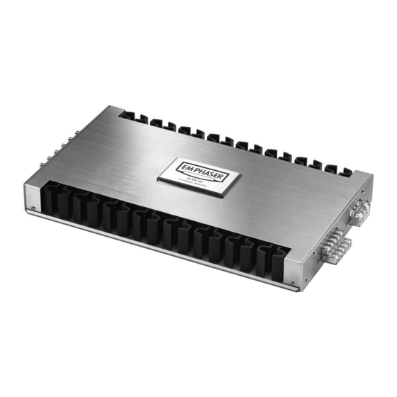
Seite 13: Technischer Aufbau / Merkmale
1. TECHNISCHER AUFBAU / MERKMALE ■ 5-KANAL CAR AUDIO VERSTÄRKER: Dieser Verstärker dient zur Realisierung eines einbau- freundlichen klangstarken und sehr leistungsfähigen Car Audio Systems mit fünf Kanälen ■ SUBWOOFER-PEGELREGELUNG ÜBER EXTERNE KABELFERNBEDIENUNG: Die im Fond des Fahrzeuges montierbare kleine Fernbedienung ermöglicht die bequeme Anpassung der Lautstärke des Subwoofers vom Fahrersitz aus ■... -
Seite 14: Anschlüsse & Bedienungselemente
2.1. EINGÄNGE & FUNKTIONEN AM FRONT PANEL EA450-250 5-KANAL VERSTÄRKER 1a/1b CINCH EINGÄNGE 1/2-CH Cinch Eingangsbuchsen 1/2-CH für den Anschluss der Cinch Ausgänge des Steuergerätes. 2a/2b CINCH EINGÄNGE 3/4-CH Cinch Eingangsbuchsen 3/4-CH für den Anschluss der Cinch Ausgänge des Steuergerätes. - Seite 15 POWER LED Grüne “Power” LED; signalisiert den normalen Betriebszustand der Endstufe im eingeschalteten Zustand. PROTECTION LED Rote “Protection” LED; signalisiert eine generelle Fehlfunktion der Endstufe, wie z.B. Kurzschluss an den Lautsprecherausgängen, Überhitzung sowie Gleichspannung an den Lautsprecher-Ausgängen. FRONT PANEL EA450-250...
-
Seite 16: Eingänge Am Rear Panel
2.2 EINGÄNGE & FUNKTIONEN AM REAR PANEL EA450-250 5-KANAL VERSTÄRKER LAUTSPRECHER AUSGANGS-TERMINAL 1/2-CH Lautsprecheranschlussterminals für den Anschluss von Lautsprechern an die Kanäle 1/2-CH des Verstärkers. LAUTSPRECHER AUSGANGS-TERMINAL 3/4-CH Lautsprecheranschlussterminals für den Anschluss von Lautsprechern an die Kanäle 3/4-CH des Verstärkers. -
Seite 17: Lautsprecher-Impedanz & Kabelinfo
Subwoofer-Kanal 2 Ohm / Satelliten-Kanäle 2 Ohm stereo oder 4 Ohms gebrückt ➡ HAUPTSTROMKABEL EMPHASER empfiehlt einen minimalen Kabelquerschnitt (bei einer Länge von 5m) von 20 – 25 mm für das +12V und das Massekabel. Falls die Endstufe an sehr niederohmigen Lasten oder im Brückenbetrieb arbeiten muss, empfiehlt sich der Einsatz von 35 mm... -
Seite 18: Verkabelung / Elektrischer Anschluss
Als Montageort eignet sich z.B. ein Platz im Kofferraum oder an einem Seitenteil, bzw jeder andere Ort, der eine saubere Installation ermöglicht. Vermeiden Sie Montageorte mit „unbekanntem Hintergrund“. Es könnten sich ein Benzintank, hydrau- lische Bremsleitungen, Kabelbäume etc. dahinter verbergen! Achten Sie auch auf einen trocken, gegen mechanische Einwirkungen geschützten Installationsort. -
Seite 19: Lautsprecherkabel
4.3 LAUTSPRECHERKABEL Schliessen Sie nun die Lautsprecher Kabel an. Entfernen Sie ca. 6-8 mm der Isolierung des LS-Kabels und beachten Sie die richtige Polung der Lautsprecherkabel am Terminal (Plus auf Plus, Minus auf Minus). Ziehen Sie die LS-Schraublemmen satt an. Schliessen Sie nun den Stromkreis zum Verstärker durch das Einsetzen der Hauptsicherung. -
Seite 20: Tiefpass Trennfrequenz Einstellung
Dabei führt eine zu tief gewählte Trennfrequenz zu einer guten Midbasswiedergabe, schränkt aber die Pegelfestigkeit stark ein. Eine zu hohe Trennfrequenzeinstellung hat einen „dünnen“ Klang mit guter Pegelfestigkeit zur Folge. Als gute Annäherungen an die übliche Praxis können folgende Einstellungen gelten: Kompo oder Koaxsystem Front („HPF“... -
Seite 21: Fine-Tuning
SUBWOOFER KANAL Drehen Sie die drei GAIN Regler an der Endstufe im Gegenuhrzeigersinn auf ihre Minimumposition. Zuerst folgt der Pegelabgleich des Subwoofersystems! Stellen Sie den Lautstärkeregler Ihres Steuergerätes auf ca. 3/4 der Maximallautstärke und benutzen Sie für die nun kommende Einstellung ein gut aufgenommenes dynamikreiches Musikstück. Drehen Sie den GAIN Regler vom Subwoofer Kanalpaar 5CH langsam im Uhrzeigersinn auf, bis Sie gerade die Verzerrungsgrenze im Bassbereich erreichen. -
Seite 23: Emphaser Limited Warranty
Should your EMPHASER product require warranty service, please return it to the retailer from whom it was purchased or the distributor in your country. Please do not send any product to EMPHASER Inc. U.S.A. Should you have difficulty in finding an authorized EMPHASER service center, details are available from your local distributor.