Inhaltsverzeichnis
Werbung
Verfügbare Sprachen
Verfügbare Sprachen
Quicklinks
FR GUIDE D'UTILISATION
DE BETRIEBSANLEITUNG
EN GUIDE TO INSTALLATION
ES MANUAL DE UTILIZACIÓN
IT MANUALE D'USO
NL GEBRUIKSAANWIJZING
PT GUIA DE UTILIZAÇÂO
CS PŘÍRUČKA K POUŽITÍ
PL INSTRUCJA OBSŁUGI
HU HASZNÁLATI UTASÍTÁS
EL ΕΓΧΕΙΡΙΔΙΟ ΧΡΗΣΗΣ
DA BRUGERMANUAL
SK PRÍRUČKA NA POUŽITIE
Hotte plan de travail
Dunstabzugshaube für arbeitsplatten
Worktop hood
Campana aspirante para mesa de trabajo
Cappa per piano di lavoro
Afzuigkap voor werkblad
Exaustor para plano de trabalho
DHD9001X
DHD9002X
DHD7000X
SV BRUKSANVISNING
Digestoř pro pracovní plochu
Okap do blatów kuchennych
Szagelszívó készülék munkatervhez
Απορροφητηρασ για παγκο κουζινασ
Emhætte til arbejdsplan
Digestor pre pracovnú plochu
Spiskåpa för innebruk
Werbung
Kapitel
Inhaltsverzeichnis

Verwandte Anleitungen für De Dietrich DHD9001X


Inhaltszusammenfassung für De Dietrich DHD9001X
- Seite 1 ES MANUAL DE UTILIZACIÓN IT MANUALE D’USO NL GEBRUIKSAANWIJZING PT GUIA DE UTILIZAÇÂO CS PŘÍRUČKA K POUŽITÍ PL INSTRUCJA OBSŁUGI HU HASZNÁLATI UTASÍTÁS EL ΕΓΧΕΙΡΙΔΙΟ ΧΡΗΣΗΣ DA BRUGERMANUAL SK PRÍRUČKA NA POUŽITIE Hotte plan de travail Digestoř pro pracovní plochu Dunstabzugshaube für arbeitsplatten Okap do blatów kuchennych Worktop hood Szagelszívó készülék munkatervhez Campana aspirante para mesa de trabajo Απορροφητηρασ για παγκο κουζινασ Cappa per piano di lavoro Emhætte til arbejdsplan Afzuigkap voor werkblad Digestor pre pracovnú plochu Exaustor para plano de trabalho Spiskåpa för innebruk DHD9001X DHD9002X DHD7000X...
- Seite 3 Le symbole sur le produit ou son emballage indique que ce produit ne peut être traité comme déchet ménager. Il doit plutôt être remis au point de ramassage concerné, se chargeant du recyclage du matériel électrique et électronique. En vous assurant que ce produit est éliminé correctement, vous favorisez la prévention des conséquences négatives pour l’environnement et la santé humaine qui, sinon, seraient le résultat d’un traitement inapproprié des déchets de ce produit. Pour obtenir plus de détails sur le recyclage de ce produit, veuillez prendre contact avec le bureau municipal de votre région, votre service d’élimination des déchets ménagers ou le magasin où vous avez acheté le produit. Cet appareil est commercialisé en accord avec la direc- tive européenne 2002/96/CE sur les dèchets del équipments èlectriques et èlctroniques (WEEE). Das Symbol auf dem Produkt oder seiner Verpackung weist darauf hin, dass dieses Produkt nicht als normaler Haushaltsabfall zu behandeln ist, sondern an einem Sammelpunkt für das Recycling von elektrischen und elektronischen Geräten abgegeben werden muss. Durch Ihren Beitrag zum korrekten Entsorgen dieses Produkts schützen Sie die Umwelt und die Gesundheit Ihrer Mitmenschen. Umwelt und Gesundheit werden durch falsches Entsorgen gefährdet. Weite- re Informationen über das Recycling dieses Produkts erhalten Sie von Ihrem Rathaus, Ihrer Mül- labfuhr oder dem Geschäft, in dem Sie das Produkt gekauft haben. Dieses Elektrohaushaltsgerät ist entsprechend der EU-Richtlinie 2002/96/CE Über Elektro- und Elektronik – Altgeräte (WEEE). The symbol on the product or on its packaging indicates that this product may not be treated as household waste. Instead it shall be handed over to the applicable col- lection point for the recycling of electrical and electronic equipment. By ensuring this product is disposed of correctly, you will help prevent potential negative consequen- ces for the environment and human health, which could otherwise be caused by inappro-...
- Seite 4 Het symbool op het product of op de verpakking wijst erop dat dit product niet als huishoudafval mag worden behandeld. Het moet echter naar een plaats worden gebra- cht waar elektrische en elektronische apparatuur wordt gerecycled. Als u ervoor zorgt dat dit product op de correcte manier wordt verwijderd, voorkomt u mogelijk voor mens en milieu negatieve gevolgen die zich zouden kunnen voordoen in geval van verkeerde afval- behandeling. Voor meer details in verband met het recyclen van dit product, neemt u het...
- Seite 5 Το σύμβολο στο προϊόν ή στη συσκευασία δείχνει ότι το προϊόν δεν πρέπει να θεωρηθεί σαν κανονικό οικιακό απόρριμμα, αλλά πρέπει να παραδοθεί στο κατάλληλο σημείο περισυλλογής για την ανακύκλωση ηλεκτρικών και ηλεκτρονικών συσκευών. Φροντίζοντας να διαθέσετε αυτό το προϊόν με κατάλληλο τρόπο, συμβάλλετε στην αποφυγή πιθανών αρνητικών συνεπειών για το περιβάλλον και την υγεία, που θα μπορούσαν να προκύψουν από μια ακατάλληλη διάθεση του προϊόντος. Για πιο λεπτομερείς πληροφορίες για την ανακύκλωση του παρόντος προϊόντος, ελάτε σε επαφή με τις δημοτικές υπηρεσίες, την τοπική υπηρεσία διάθεσης απορριμμάτων ή το κατάστημα στο οποίο αποκτήσατε το προϊόν. Η παρούσα ηλεκτρική συσκευή έχει σημανθεί σύμφωνα με την Ευρωπαϊκή Οδηγία 2002/96/CE σχετικά με τα απορρίμματα από τις ηλεκτρικές και ηλεκτρονικές συσκευές (WEEE). Symbolet på produktet eller konfektionen indikerer at produktet ikke bør an- ses som normalt husholdningsaffald, men i stedet skal det bringes til et sted der har med genbrug af elektriske og elektroniske apparater at gøre. Ved bortskaffelse af dette pro-...
- Seite 6 Votre nouvelle hotte DE DIETRICH s’intègrera harmonieusement dans vo- tre cuisine et alliera parfaitement les performances d’aspiration, et la facilité d’utilisation. Nous avons voulu vous offrir un produit d’excellence. 68 Vous trouverez également dans la gamme des produits DE DIETRICH, un vaste choix de fours, de fours à micro-ondes, de tables de cuisson, de lave- vaisselle, et de réfrigérateurs intégrables, que vous pourrez coordonner à votre nouvelle hotte DE DIETRICH. Bien entendu, dans un souci permanent de satisfaire le mieux possible vos 99 exigences vis à vis de nos produits, notre service consommateurs est à votre...
-
Seite 7: Inhaltsverzeichnis
SOMMAIRE 1/ A L’ATTENTION DE L’UTILISATEUR - Consignes de sécurité - Montage de votre hotte - Description de votre appareil 2 / COMMENT INSTALLER VOTRE HOTTE - Montage du moteur séparé - Montage et démontage des filtre anti-graisse - Montage et démontage des filtres charbon - Raccordement de votre hotte 3 / COMMENT FONCTIONNE VOTRE HOTTE 4 / COMMENT NETTOYER VOTRE HOTTE 5 / ANOMALIES DE FONCTIONNEMENT 6 / SERVICE APRES-VENTE - Interventions - Relations consommateurs... -
Seite 8: 1/ A L'attention De L'utilisateur
1/ A L’ATTENTION DE L’UTILISATEUR Important: Conservez cette notice d’utilisation avec votre appareil. Si l’appareil devait être vendu ou cédé à une autre personne, assurez-vous que la notice d’utilisation l’accompa- gne. Merci de prendre connaissance de ces conseils avant d’installer et d’utiliser votre appareil. Ils ont été rédigés pour votre sécurité et celle d’autrui. Le constructeur décline toute responsabilité pour tous les inconvénients, dommages ou incendies provoqués sur et par l’appareil et dus à la non observatiôn des instructions de la présente notice. -
Seite 9: Montage De Votre Hotte
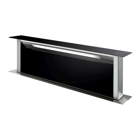
évacué ne doit pas être envoyé dans un conduit utilisé pour évacuer les fumées d‘appareils utilisant du gaz ou autre combustible. L‘utilisation de conduits désaffectés ne peut se faire qu‘après accord d‘un spécialiste compétent. 1/ A L’ATTENTION DE L’UTILISATEUR - DESCRIPTION DE VOTRE APPAREIL DHD7000X DHD9002X DHD9001X... -
Seite 10: Comment Installer Votre Hotte
2/ COMMENT INSTALLER VOTRE HOTTE 1) Pour le bon fonctionnement de la hotte, il est important d’effectuer une installation correcte Avant de commencer l’installation 2) Avant d’installer votre appareil, enlever la partie de sécurité, comme indiqué en fig. 2a-2b-2c-2d. 3) Le moteur est livré, fixé sur l’appareil afin d’éviter tout dommage pendant le transport. Il est nécessaire de le démonter avant de commencer les opérations d’installation. 4) Sur la partie arrière du plan de cuisine, effectuer un trou rectangulaire adaptés aux dimensions de votre hotte (voir dessin 3A et 3B). 5) La distance maximum autorisée entre le trou à réaliser pour la hotte et le plan de cuisson est de 6 cm. La hotte doit impérativement reposer sur les 4 côtés. Pour le modéle DHD9001X: l’installatiòn se fait entre 2 tables de cuisson de 2 foyers maximum chacune (Fig 3C)”. 6) Avant de faire le trou, vérifier, dans la partie interne du meuble, en correspondance de la zone de logement de la hotte, l’absence de structure du meuble ou d’autres éléments pouvant compromet- tre une installation correcte. Vérifier que les encombrements de la hotte avec son moteur ainsi que du plan de cuisson soient compatibles avec le meuble pour permettre l’installation. 7) Appliquer de la colle sur le cadre de la partie inférieure de l’encadrement (fig. 10,11,12) et le positionner à l’intérieur du trou réalisé sur le plan de cuisson. Ensuite insérer la hotte à l’intérieur du meuble. L’installation 8) Installer la hotte à l’intérieur du meuble, en l’introduisant par le haut. 9) L’encadrement en acier de la hotte doit adhérer parfaitement au plan supérieur de la cuisine. 10) Fixer la hotte à l’intérieur du meuble en utilisant les brides spécifiques (Dessin A fig. 5). Selon les dimensions du meuble et les encombrements du tube de sorite de l’air. Utiliser les brides de fixation fournies en dotation. Le moteur 11) Procéder au montage du moteur sur le corps de la hotte en orientant la sortie de l’air sur la position choisie, vers le bas ou vers le haut (dessin 5). REMARQUE: Le moteur peut-être fixé soit à l’avant soit à l’arrière du produit. 12) Pour une installation à l’arrière, veuillez procéder de la façon suivante: - Dévisser la plaque en tôle située à l’arrière de la hotte - Visser le moteur à la place de la tôle arrière - Connecter correcte- ment le câble moteur - Enfin revisser la plaque en tôle à l’avant. - Procéder au montage du tuyau d’évacuation de l’air (non fourni). -
Seite 11: Montage Du Moteur Séparé
Après avoir achevé la procédure d’auto-calibration, frapper la touche ainsi que la partie extractible descend. Ensuite allumer la hotte. Ouvrir ensuite le portillon (fig. 1D/1E) et retirer la protection en PVC du filtre anti-graisse et positionner les filtres comme indiquée en fig. 1F. Attention: La calibration doit être fate correctement, car cela contribue à votre sécurité lors de l’utilisation de l’appareil et notamment au réglage de la sécurité anti-pincement. UTILISATION Cette hotte est prévue pour l’aspiration des fumées, graisses et vapeurs de cuisson. Elle est réalisée de façon qu’elle puisse être utilisée en version évacuation ou en version recyclage. Version évacuation extérieure La hotte est équipée d’une sortie de l’air (Fig.A dessin 4). Pour l’évacuation des fumées vers l’extérieur (tuyau d’évacuation et colliers de fixation non fournis). Blocage du clapet anti-retour Attention! avant de connecter la gaine flexible de sortie d’air au moteur, s’assurer que le clapet anti-retour puisse tourner librement. Dans le cas d’une instalation en evacuation exterieure, l’installation du clapet anti-retour empèche l’entrèe du vent et le retour d’air. -
Seite 12: Raccordement De Votre Hotte
RACCORDEMENT DE VOTRE HOTTE AVERTISSEMENT : Le boitier électronique de commande doit être installé sous le plan de travail à proximité du corps de la hottes et à 65cm au moins de toute substance ou ca- nalisation contenant une substance inflammable (canalisation de gaz, liquide spécifique d’entretien.) RECOMMANDATION : Nous vous recommandons d’installer le boitier électronique à... -
Seite 13: Comment Fonctionne Votre Hotte
3/ COMMENT FONCTIONNE VOTRE HOTTE : Elle a la fonction de fermeture du panneau d’aspiration soit complétament, soit Touche sur des positions intermédiaires au-dessus de 18 cm du plan de cuisson ; durant la fermeture le panneau d’aspiration demeure en fonction à la vitesse établie jusqu’à la hauteur de 18 cm au- dessus du plan de cuisson. En-dessous de cette mesure, la fonction d’aspiration s’interrompt automatiquement. Touche : Elle a la fonction d’extraction du panneau d’aspiration jusqu’à la hauteur maxi- mum de 30 cm et de programmation automatique de la première vitesse d’aspiration lorsqu’on atteint la hauteur de 18 cm au-dessus du plan de cuisson. En frappant à nouveau la touche, après avoir atteint cette dimension, il est possible d’augmen- ter la vitesse du moteur d’aspiration. Si le panneau d’aspiration est positionné à une hauteur intermédiaire comprise entre 18 cm et 30 cm, il est possible de réactiver la montée du panneau d’aspiration en agissant d’abord sur la touche puis sur la touche . Voyants lumineux Les vitesses de fonctionnement sont indiquées par les voyants lumi- neux bleu (1° vitesse voyant en bas à gauche). TOUCHE : Elle est active seulement si la hauteur du panneau d’aspiration est supérieure à 18 cm au-dessus du plan de cuisson et elle permet de réduire la vitesse du moteur d’aspiration. : Elle a la fonction d’arrêt automatique du dispositif d’aspiration et de fermeture TOUCHE automatique du panneau d’aspiration dix minutes après sa programmation. Autres fonctions: - Après 30 heures de fonctionnement de l’appareil, le clavier de commande signale la saturation des filtres anti-graisse à travers le clignotement des voyants lumineux; pour la mise à zero, frapper la touche minuterie . -
Seite 14: Comment Nettoyer Votre Hotte
4/ COMMENT NETTOYER VOTRE HOTTE Un entretien soigné est une garantie de bon fonctionnement et de bon rendement de votre appareil dans le temps. La hotte doit être mise hors tension, soit en retirant la prise, soit en actionnant le disjoncteur, avant que les filtres métalliques soient enlevés. Après le nettoyage, les filtres métalliques doivent être de nouveau fixés conformément aux instructions. -
Seite 15: Anomalies De Fonctionnement
5/ ANOMALIES DE FONCTIONNEMENT SYMPTOMES SOLUTIONS La hotte ne fonctionne Vérifiez que: pas... • il n’y a pas de coupure de courant. • Le bouton rouge du boitier séparé est bien enfoncé. • une vitesse a été effectivement sélectionnée. • la hauteur de la hotte est supérieure à 18 cm. • le panneau central a été correctement repositionné. • le clapet anti-retour peut bouger librement. • l’air aspiré est évacué correctement du meuble. La hotte a un rende- Vérifiez que: ment insuffisant... • la vitesse moteur sélectionnée est suffisante pour la quantité de fumée de vapeur dégagée. • la cuisine est suffisamment aérée pour permettre une prise d’air. • le filtre à charbon n’est pas usagé (hotte en version recyclage). • le filtre graisse ne soit pas chargé en graisse • la distance maximum entre la table et la hotte ne soit pas dépassé. • cette hotte soit adaptée aux dimensions de votre cuisine. La hotte s’est arrêtée Vérifiez que: au cours du fonction-... -
Seite 16: Service Apres-Vente
- RELATIONS CLIENTS Pour en savoir plus sur tous les produits de la marque: informations, conseils, les points de vente, les spécialistes après-vente. Pour communiquer: nous sommes à l’écoute de toutes vos remarques, suggestions, propositions auxquelles nous vous répondrons personnellement. Vous pouvez nous écrire: SERVICE CONSOMMATEURS DE DIETRICH BP 9526 95069 GERGY PONTOISE CEDEX 0892 02 88 04* ou nous téléphoner au: 0,34 euro TTC/mn à partir d’un poste fixe => tarif en vigueur à la date d’impression du document. - Seite 17 Sehr geehrter Kunde, 6 Wir bedanken uns bei Ihnen, dass Sie sich für eine Dunstabzugshaube von DE DIETRICH entschieden haben. Unsere Forschungsteams haben für Sie eine neue Generation an Geräten en- twickelt, die in ihrer ästhetischen Qualität, in ihrer Funktionalität und in ihrer technischen Entwicklung außergewöhnliche Produkte darstellen und so un- sere Erfahrung bezeugen. Ihre neue Dunstabzugshaube von DE DIETRICH fügt sich harmonisch in ihre Küche und vereint Abzugsleistung und leichte Handhabung vollkommen. Wir bieten Ihnen ein unübertreffliches Produkt. 68 In der Produktpalette von DE DIETRICH können Sie darüber hinaus eine große Auswahl an Öfen, Mikrowellen, Kochfeldern, Geschirrspülmaschinen und ein- baubaren Kühlschränken finden, die sich frei mit Ihrer Dunstabzugshaube kombinieren lassen. Da unser Ziel natürlich die Kundenzufriedenheit mit unseren Produkten ist, 99 steht Ihnen unser Kundenservice zur vollen Verfügung, um Anfrage jeder Art zu beantworten und nützliche Hinweise entgegen zu nehmen (Kontak- thinweise finden Sie am Ende dieser Anleitung).
- Seite 18 INHALT 1 / ALLGEMINE HINWEISE - Sicherheitshinweise - Einbau der Dunstabzugshaube - Gerätebeschreibung 2 / INSTALLATION DER DUNSTABZUGSHAUBE - Einbau des separaten motors - Erausnehmen der filterpatrone - Einsetzen der Kohlefilter - Stromanschluss der Dunstabzugshaube 3 / FUNKTIONSWEISE DER DUNSTABZUGSHAUBE 4 / REINIGUNG DER DUNSTABZUGSHAUBE 5 / UNREGELMÄSSIGKEITEN IN DER FUNKTIONSWEISE 6 / KUNDENDIENST...
-
Seite 19: Allgemine Hinweise
1/ ALLGEMINE HINWEISE Wichtig: Bewahren Sie die vorliegende Bedienungsanleitung mit dem Gerät auf. Sollte das Gerät verkauft oder abgegeben werden, vergewissern Sie sich, dass die mit der vorliegenden Bedienungsanleitung geschieht. Wir danken Ihnen dafür, dass Sie die Hinweise vor der Instal- lation und Inbetriebnahme des Gerätes beachten. Dies dient Ihrer Sicherheit und der Sicherheit anderer. Der Hersteller haftet nicht für eventuelle Störungen, Schäden oder Brände, die am oder durch das Gerät entstehen und auf die Nichteinhaltung der in diesem Heft enthaltenen Anweisungen zurück zu führen sind. - SICHERHEITSHINWEISE Diese Abzugshauben wurden für den häuslichen Gebrauch durch Privatpersonen entwickelt. -
Seite 20: Einbau Der Dunstabzugshaube
Um zukünftig die Daten bezüglich Ihres Gerätes schnell zur Hand zu haben, raten wir Ihnen die- se auf der Seite „Kundenbetreuung nach Kauf“ einzutragen. (Auf dieser Seite wird Ihnen darüber hinaus erklärt, wo Sie die entsprechenden Daten an Ihrem Gerät finden können). Niemals die Dunstabzugshaube ohne Fettfilter benutzen. Der Sicherheitsabstand zwischen der Dunstabzugshaube und der Kochplatte muss mindestens 400 mm betragen. Während der Handhabung des Geräts, die Hände vom Arbeitskreis fernhalten. - EINBAU DER DUNSTABZUGSHAUBE Die Installation muss entsprechend den geltenden Vorschriften bezüglich einer au- sreichenden Belüftung von geschlossenen Räumen durchgeführt werden. In Frankreich sind diese Vorschriften in DTU 61.1 des CSTB enthalten. Im Besonderen darf die abzu- gebende Luft nicht in Luftschächte geführt werden, die für den Abzug von Rauch oder anderen Gas- und Brennstoffgeräten benutzt werden. -
Seite 21: Gerätebeschreibung
1/ ALLGEMINE HINWEISE - GERÄTEBESCHREIBUNG DHD7000X DHD9002X DHD9001X... -
Seite 22: Installation Der Dunstabzugshaube
4) Ein geeignetes rechteckiges Loch in die Hinterseite der Kochplatte für die Einrichtung der Dunstsabzugshaube durchführen (siehe Bild 3A u. 3B). 5) Der Sicherheitsabstand zwischen dem Loch für die Einrichtung des Geräts und der Kochplatte muss maximal 6 cm betragen. Die Dunstabzugshaube muss durchaus auf den 4 Seiten stehen. Für das Modell DHD9001X: der Einbau erfolgt zwischen 2 Kochplatten mit jeweils 2 Brenner (Bild 3C). 6) Bevor Sie die Öffnung herstellen, überprüfen Sie im Inneren des Schranks im Bereich der Abzugshaube, dass keine Strukturteile oder sonstigen Elemente die korrekte Installation beein- trächtigen können. Überprüfen Sie, dass die Abmessungen der Abzugshaube mit ihrem Motor... -
Seite 23: Einbau Des Separaten Motors
3- Nachher die Taste drücken, innerhalb zwei Sekunden, und dann die Taste (simbolo). Das Gerät führt die Kalibrierung der Filtereinheit automatisch durch und verstellt sie wenige Zenti- meter nach oben oder nach unten; während des Verfahrens blinken die Tasten der Bedienleiste. Nach Beendung der automatischen Kalibrierung, die Taste drücken, damit der ausziehbare Korpus senkt. Danach die Dunstabzugshaube einschalten. Das Filterfach öffnen (Bild 1D/1E) und den PVC-Schutz vom Fettfilter entfernen: die Filter wie im Bild 1F einsetzen. Achtung: für eure Sicherheit während der Verwendung des Geräts und insbesondere für die Anti-Kneifen Regelung, muss die Kalibrierung richtig durchgeführt sein. Verwendung Diese Abzugshaube wurde für das Absaugen von Rauch, Fett und Dampf während des Kochens entwickelt. Sie wurde so realisiert, dass sowohl der Ausstoß der Luft nach außen, als auch die Umwälzung möglich ist. Ausführung mit Ausstoß nach außen Die Abzughaube ist mit einem Luftablass ausgestattet (Abb. A, Zeichng. 5) Zum Ausstoß des Rauchs nach außen (Auslassrohr und Befestigungsbügel werden nicht mit- geliefert). -
Seite 24: Herausnehmen Der Filterpatrone - Einsetzen Der Kohlefilter
- HERAUSNEHMEN DER FILTERPATRONE - EINSETZEN DER KOHLEFILTER Während der Einsetzung und der Beseitigung der Fettfilter und der Kohlenfilter, muss sich die Dunstabzugshaube in offener Lage befinden . Dann die Fronttafel durch Drücken im oberen Bereich auf allen Seiten entfernen (Abb. 1d). Die Frontplatte dreht sich nach vorn und gibt den Zugang zu den Fettfiltern (Abb. 8b) frei. Die Fettfilter entfernen, um Zugang zu den Kohlefil- tern (Abb. 9c) zu bekommen. Die Häufigkeit des Wechsels der Kohlefilter ist davon abhängig, wie oft die Versenkklappe benutzt wird. Der Austausch muss jedoch mindestens alle 6 Monate erfolgen. Achtung: Die Edelstahltafel zum Schutz der Filter muss wieder korrekt positioniert werden. Schlechte Positionierung kann zum völligen Stillstand der Abzugshaube führen. - SROMANSCHLUSS DER DUNSTABZUGSHAUBE HINWEIS: die elektronische Steuerkarte muss unter der Arbeitsfläche in der Nähe der Abzugshaube installiert werden und muss mindestens 65 cm von allen brennbaren Su- bstanzen bzw. -
Seite 25: Funktionsweise Der Dunstabzugshaube
3/ FUNKTIONSWEISE DER DUNSTABZUGSHAUBE Diese hat die Funktion, die Absaugplatte sowohl vollständig als auch auf Zwischenpo- Taste sitionen über 18 cm oberhalb der Herdplatte zu fahren. Während des Verfahrens bleibt die Absaugtafel bei der eingestellten Geschwindigkeit auf 18 cm Höher über der Herdplatte in Betrieb. Unterhalt dieses Maßes wird die Absaugfunktion automatisch abgebrochen. Taste Diese hat die Funktion, die Absaugtafel bis auf die maximale Höhe von 30 cm auszu- fahren und bei Erreichen von 18 cm Höhe über der Herdplatte automatisch die erste Absaugge- schwindigkeitsstufe einzustellen. Wird die Taste nach Erreichen dieser Höhe weiterhin betätigt, kann die Geschwindigkeit des Absaugmotors erhöht werden. -
Seite 26: Reinigung Der Dunstabzugshaube
4/ REINIGUNG DER DUNSTABZUGSHAUBE Eine sorgfältige Pflege garantiert auf Dauer eine gute Leistung und Funktionstüchtigkeit des Geräts. Die Dunstabzugshaube muss vom Stromnetz getrennt werden, bevor die Metallfilter entnommen werden können. Nach der Reinigung sind die Metallfilter wie in der Anleitung beschrieben wieder einzusetzen. WARTUNG PUTZ- UND HILFSMITTEL WIE IST VORZUGEHEN? Äußere Verwenden Sie keinesfalls Metall- Um die Oberfläche der Abzugshaube Geräteober- schwämme, Scheuermittel oder zu... -
Seite 27: Unregelmässigkeiten In Der Funktionsweise
5/ UNREGELMÄSSIGKEITEN IN DER FUNKTIONSWEISE ANZEICHEN LÖSUNG Die Abzugshaube Versichern Sie sich, dass: funktioniert nicht. • kein Stromausfall besteht, • die gewünschte Betriebsstufe wirklich ausgewählt wurde. • Die rote Taste des separaten Teils ist richtig eingeschaltet • Der Abstand des Geräts überragt 18 cm. • Das mittlere Paneel ist wieder richtig eingesetzt • Das Rückschlagventil ist nicht fest • Die abgesaugte Luft wird korrekterweise aus dem Möbel evakuiert Die Abzugshaube Versichern Sie sich, dass: funktioniert nicht ri- chtig. • die Motorgeschwindigkeit für die Rauch- und Dampfmenge hoch genug gewählt ist, • die Küche ausreichend belüftet ist, um einen notwendigen Luf- tansog zu gewährleisten, • der Kohlefilter ist schon benutzt worden (Recycling Version) • der Fettfilter ist schmutzig • der Minestabstand zwischen der Kochplatte und der Dunsta- bzugshaube ist überschritten worden • die Dunstabzugshaube ist für die Größe ihrer Küche nicht geei-... - Seite 28 Dear client, 6 You have just purchased a DE DIETRICH range ventilation hood, and we thank you for your purchase. Our research and development teams have designed a new generation of appliances for you, which, because of their aesthetics, functionality, and te- chnological evolution, are truly exceptional products representative of our design experience. Your new DE DIETRICH range ventilation hood will harmoniously suit your kitchen and will perfectly combine ventilation performance and ease of use.
- Seite 29 CONTENTS 1 / TO THE ATTENTION OF THE USER - Safety instructions - Mounting the hood - Description of the applianc 2 / INSTALLING THE HOOD - Remote motor installation - Removal of the filter cartridge - Mounting the carbon filter - Electrical hook-up of the hood 3 / HOW THE HOOD WORKS 4 / CLEANING THE HOOD 5 / OPERATIONAL ANOMALIES 6 / AFTER SALES SERVICE...
-
Seite 30: To The Attention Of The User
1/ TO THE ATTENTION OF THE USER Important: keep these instructions for use with the appliance. If the appliance should be sold or passed on to others, make sure that the instructions are passed on with it. We thank you for taking note of these suggestions before installing and using the appliance. They have been written for your personal safety and the safety of others. The manufacturer cannot be held liable for any problems, damage of fires caused on or by the appliance and arising from failure to follow the instructions in this handbook. - SAFTEY INSTRUCTIONS These hoods have been designed for personal use in the home. The appliance must be used by adults.Take care that children do not touch the appliance and do not use it as a toy. Make sure... -
Seite 31: Description Of The Applianc
1/ TO THE ATTENTION OF THE USER - DESCRIPTION OF THE APPLIANCE DHD7000X DHD9002X DHD9001X... -
Seite 32: Installing The Hood
2/ INSTALLING THE HOOD 1) For the correct operation of the Downdraft, it is important for it to be installed correctly. Before proceeding with installation 2) Before installing your appliance, remove all safety protections as illustrated in Fig. 2 - 2b – 2c – 2d. 3) The motor is delivered fixed to the appliance to prevent any damage during transport. It is necessary to remove the motor prior to beginning the installation. 4) Drill a rectangular hole suitable to the cooker hood dimension in the rear side of the cook top (see figure 3A and 3B). 5) The maximum distance allowed between the hole to be drilled, for the cooker hood, and the cook top is 6 cm. The cooker hood must absolutely rest on all 4 sides. For the DHD9001X model only: installation is carried out between two cook tops with 2 maximum burners for each one. (Fig. 3C) 6) Before making the opening, check the inside of the cabinet level with the hood area to make sure there is no framework or other elements that could adversely affect the correct installation. Make sure that the size of the hood with its motor and the work top are compatible with the unit so as to allow installation. 7) Apply some glue on the trim of the lower side of the cooker hood. (Fig. 10-11-12) and place it inside the opening in the kitchen top. Then fit the Downdraft inside the unit. Installation 8) Fit the hood inside the unit, introducing it from above. 9) The steel cornice of the hood must adhere perfectly to the upper kitchen top. 10) Fasten the hood inside the unit, using the special brackets (Fig. 5 A). According to the size of the unit and the overall size of the air exhaust tube, use the fastening brackets provided. -
Seite 33: Remote Motor Installation
3 - Push the (simbolo) key, within two seconds, and then the key. The cooker hood carries out the filtering unit calibration moving it downwards or upwards for some centimetres; during this phase, the keys on the keypad will flash. Once the self-calibration procedure has been completed, push the key so that the ex- tractable unit moves downwards. Turn the cooker hood on afterwards. Then open the little door (Fig. 1D/1E) and remove the PVC protection from the grease filter; then install the filters as shown in fig. 1F. Attention: the cooker hood calibration should be carried out properly, so that your safety can be assured during the usage of the appliance and, especially, in the adjustment of anti-deflection safety. UTILISATION This product is intended to extract fumes, fats, and steam from cooking. It has been designed and made for use either in the suction or filter versions. VERSION EVACUATION exterieure The hood is equipped with an air outlet (Fig. A FIGURE 5) to convey smoke outwards (the flue pipe and fixing flange are not supplied). Check valve blockage Warning: Before connecting the air exhaust hose, make sure that the check valves are free to turn over freely. In filtering application that the stop valve doesn’t permit the entrance of wind and exhau- sted air. -
Seite 34: Removal Of The Filter Cartridge
-REMOVAL OF THE FILTER CARTRIDGE -MOUNTING THE CARBON FILTER The cooker hood must be in the open position to install and remove its grease filters and char- coal filters. Push this key to do so. Next remove the front panel, pushing on both sides of the top part at the same time (Fig. 1d). The panel will rotate forwards to make it possible to access the grease filters (Fig. 8b). Remove the grease filters to access the carbon filters (Fig. 9c). The carbon filters should be changed according to the frequency of downdraft use and in any case, once every 6 months. Warning: the stainless steel panel that protects the filters needs to be repositioned correctly. Incorrect positioning can cause the hood to stop completely. - ELECTRIAL HOOK UP OF THE HOOD WARNING: The electronic board for the controls needs to be installed beneath the work top, close to the body of the hood and at a minimum distance of 65 cm from all substances or ducting for flammable substances (gas pipes or ducting for specific liquids) USEFUL ADVICE: We recommend fitting the electronic board at a height of at least 10 cm from the ground and at a suitable distance from all heat sources... -
Seite 35: How The Hood Works
3/ HOW THE HOOD WORKS OFF switch: It is used to close the aspiration panel completely or to position it at interme- diate heights at least cm 18 above the cooktop. While closing the aspiration panel keeps on working at the speed set up to the height of cm 18 from the cooktop. Below this height the aspiration function is automatically cut out. On switch/+: It is used to extract the aspiration panel up to the maximum height of cm. 30 and to set automatically the first aspiration speed when reaching the height of cm 18 from the cooktop. When pressing the button again after reaching this height, the aspiration motor speed can be encreased. If the aspiration panel is positioned at an intermediate height between cm 18 and cm 30, the aspiration panel can start raising again by pressing first the OFF switch and then the On/+. Switch . Leds: The different speed levels are indicated by blue leds. (1. Speed level corresponds to the led down on the left). MINUS SWITCH: it is working only if the position reached by the aspiration panel is higher than mm 180 from the cooktop. It is used to decrease the aspiration motor speed. TIMER SWITCH: it is used to stop automatically the aspiration system and to close auto- matically the aspiration panel ten minutes it has been set. -
Seite 36: Cleaning The Hood
4/ CLEANING THE HOOD Careful maintenance helps guarantee proper operation and good results from an appliance over time. The hood must be unplugged from the electrical power source, both by unplugging the appliance from the socket as well as de-activating the breaker, before removing the metal fil- ters. After cleaning, you must replace the metal filters as outlined in the instructions. MAINTENANCE ACCESSORY PRODUCTS TO USE HOW TO PROCEED? -
Seite 37: Operational Anomalies
5/ OPERATIONAL ANOMALIES SYMPTOM SOLUTION The hood does not Check that: work... • there is not a power outage. • a specific speed has actually been selected. • the red button, of the separate body, is inserted properly. • the cooker hood height exceeds 18 cm. • the central panel has been repositioned properly. • The non-return valve moves freely. • The air suctioned is discharged properly from the cabinet. The hood has low ou- Check that: tput... • the motor speed selected is sufficient for the quantity of fumes steam present. • the kitchen is ventilated well enough to allow for air intake. • the charcoal filter has not been used (filtering mode version). • the grease filter is not saturated. • the minimum distance between the cooker hood and the cook top has not been exceeded, • this cooker hood is suitable for your kitchen dimensions. The cooker hood does Check that: not close again. • an obstacle prevents the appliance from being closed completely. In case of malfunctioning, after all the After-Sale service works, it is necessary to carry out the cooker hood calibration again . 6/ AFTER SALES SERVICE Any maintenance on your equipment should be undertaken by: - either your dealer, - or another qualified mechanic who is an authorized agent for the brand appliances. - Seite 38 Estimado cliente, 6 Le agradecemos que Usted haya comprado una campana DE DIETRICH. Nuestros equipos de investigación han proyectado para usted una nueva ge- neración de aparatos que, por su calidad estética, funcionalidad y evolución tecnológica representan productos excepcionales que son la prueba de nue- stra experiencia. Su nueva campana DE DIETRICH se integrará con armonía en su cocina y conjugará perfectamente capacidad de aspiración y facilidad de empleo. He- mos querido ofrecerle un producto excelente. En la gama de los productos DE DIETRICH podrá encontrar además una am- plia variedad de hornos, hornos microondas, encimeras, lavavajillas, frigorí- 68 ficos empotrados, que se pueden coordinar libremente con su nueva campa- na DE DIETRICH. Como nuestro objetivo, naturalmente, coincide con la satisfacción de nue- stros clientes por nuestros productos, nuestro servicio de consumidores está a su completa disposición, para responder a cualquier necesidad y para...
- Seite 39 ÍNDICE 1 / A LA ATENCIÓN DE LOS SEÑORES USUARIOS - Instrucciones de seguridad - Montaje de la campana - Descripción del aparato 2 / CÓMO INSTALAR LA CAMPANA - Montaje del motor separado - Desmontaje del filtro de cartucho - Montaje del filtro de carbono - Enlaces eléctricos de la campana 3 / CÓMO FUNCIONA LA CAMPANA 4 / CÓMO LIMPIAR LA CAMPANA 5 / DEFECTOS DE FUNCIONAMIENTO 6 / SERVICIO POSTVENTA...
-
Seite 40: A La Atención De Los Señores Usuarios
1/ A LA ATENCIÓN DE LOS SEÑORES USUARIOS Importante: conservar estas instrucciones de uso junto con el aparato. Si el aparato se tuviera que vender o ceder a otras personas, asegurarse de que vaya acompañado de estas instrucciones. Agradecemos que tome nota de estos consejos antes de instalar y utilizar el aparato. Han sido redactados por su seguridad personal y la de los demás. El Constructor no será... -
Seite 41: Descripción Del Aparato
1/ A LA ATENCIÓN DE LOS SEÑORES USUARIOS - DESCRIPCIÓN DEL APARATO DHD7000X DHD9002X DHD9001X... -
Seite 42: Cómo Instalar La Campana
2/ COMO INSTALAR LA CAMPANA 1) Para el buen funcionamiento de la campana retráctil (Downdraft), es importante efectuar una instalación correcta Antes de comenzar la instalación 2) Antes de instalar su aparato, quite las protecciones de seguridad, como se indica en la Fig. 2° - 2b – 2c – 2d. 3) El motor se entrega fijado al aparato para que no sufra ningún daño durante el transporte. Hay que desmontarlo antes de empezar las operaciones de instalación. 4) En la parte trasera de la encimera hacer un agujero rectangular del tamaño apropiado de la campana (ver fig. 3A y 3B). 5) La distancia máxima permitida entre el agujero de la campana que se tiene que hacer y la en- cimera es de 6 cm. La campana debe estar apoyada en los 4 lados. para el modelo DHD9001X: la instalación se hace con 2 encimeras con un máximo de 2 quemadores para cada una (Fig. 3C). 6) Antes de realizar el agujero, compruebe en la parte interior del mueble, en correspondencia con la zona de la campana, que no esté la estructura móvil ni otros elementos que puedan poner en peligro la instalación correcta. Asegúrese de que las dimensiones de la campana con su motor, así como el plano de cocina, sean compatibles con el mueble para permitir la instalación. 7) Aplique el pegamento en la parte inferior de la campana (fig. 10-11-12) y colóquelo dentro del agujero realizado en el plano cocina. A continuación, introduzca la campana retráctil (Downdraft) dentro del mueble. La instalación 8) Instale la campana dentro del mueble introduciéndola desde arriba. 9) El marco de acero de la campana debe adherirse perfectamente al plano superior de la cocina. 10) Fije la campana dentro del mueble utilizando las abrazaderas específicas (dibujo 5 A). Según las dimensiones del mueble y las del tubo para la salida del aire, escogiendo entre las abraza- deras que le suministramos junto con la campana. El motor 11) proceder al montaje del mmotor en el cuerpo de la campana orientando la salida de aire en la posición deseada, hacia arriba o hacia abajo (Fig. 5). Nota: 12) El motor se puede fijar tanto en la parte delantera como en la trasera del producto. Para... -
Seite 43: Montaje Del Motor Separado
3-A continuación, pulse el botón , dentro de dos segundos y, despues, el botón (símbolo). La campana realiza la calibración del filtro moviendolo hacia abajo o hacia arriba de unos centí- metros, durante esta fase se prenden y se apagan las luces de las teclas del teclado. Después de terminar la operación de auto-calibración, presione el botón , de modo que la parte extraible baje. Después encender la campana. A continuación, abra la puertita (Fig. 1D/1E) y elimine la protección de PVC del filtro antigrasa, coloque los filtros como se muestra en la fig. 1F. Advertencia: La calibración se debe realizar correctamente, porqué contribuye a su seguridad mientras se utiliza el aparato y, sobretodo en la regulación de la seguridad anti-aplastamiento. La presente campana se ha proyectado para aspirar los humos, las grasas y los vapores de coc- ción. Se ha realizado para que pueda ser utilizada tanto en versión con descarga al exterior como en versión con reciclaje. Versión con descarga al exterior La campana está dotada de una descarga de aire (Fig. A dib. 5) Para descargar los humos hacia el exterior (tubo de descarga y estribos de fijación no sumini- strados). Bloqueo de la válvula sin retorno Atención^ antes de conectar el tubo flexible de salida del aire asegurarse de que las válvulas sin retorno estén libres para girar libremente. La instalación de la válvula de no retorno impide la entrada de viento y el retorno de aire. -
Seite 44: Desmontaje Del Filtro De Cartucho
-DESMONTAJE DEL FILTRO CARTUCHO -MONTAJE DEL FILTRO CARBÓN La campana debe estar en la posición de apertura para el montaje y desmontaje de los filtros antigrasa y filtros de carbón. Para ello pulse el botón . A continuación, extraiga el panel frontal empujándolo simultáneamente por ambos lados de la parte superior (Fig. 10). El panel rota hacia adelante, liberando el acceso a los filtros antigrasa (fig. 8b). Retire los filtros an- tigrasa para poder acceder a los filtros carbón (fig. 9c). El cambio de los filtros carbón debe realizarse en función de la frecuencia de uso de la campana retráctil (downdraft), y, de todas formas, una vez cada 6 meses. Atención: El panel de acero inoxidable que protege los filtros debe colocarse correctamente. Una mala colocación puede provocar la parada total de la campana. - CONEXIÓN ELÉCTRICA DE LA CAMPANA ADVERTENCIA: La tarjeta electrónica de los mandos se debe instalar bajo la superficie de trabajo cerca del cuerpo de la campana y a 65cm. -
Seite 45: Cómo Funciona La Campana
3/ COMO FUNCIONA LA CAMPANA Botón OFF Tiene la función de cierre del panel aspirante sea en forma total que en posi- ciones intermedias por encima de 18 cm desde la encimera, durante el cierre el panel aspirante permanece en función a la velocidad establecida hasta una altura de 18 cm desde la encimera. Por debajo de dicha dimensión la función de aspiración se interrumpe automáticamente. Botón On/+ Tiene la función de extracción del panel aspirante hasta una altura máxima de 30 Cm y de programación automática de la primera velocidad de aspiración cuando se al- canza la altura de 18 cm desde la encimera. Apretando ulteriormente el botón después de haber alcanzado dicha dimensión se puede au- mentar la velocidad del motor de aspiración. En el caso en que el panel aspirante esté colocado a una altura intermedia comprendida entre 18 cm y 30 cm es posible reiniciar la subida del panel aspirante primero mediante el botón y sucesivamente con el botón . velocidad led Leds Las velocidades de funcionamiento son indicadas por los leds azul (1 parte baja a la izquierda). Está activo sólo si la altura del panel aspirante es superior a los 18 cm BOTÓN MENOS desde la encimera y permite reducir la velocidad del motor de aspiración. BOTÓN TEMPORIZADOR Tiene la función de detención automática del sistema de aspi- ración y de cierre automático del panel aspirante después de diez minutos a partir de su pro- gramación. Otras funciones: - Después de 30 horas de funcionamiento del aparato la botonera muestra la saturación de los filtros antigrasa mediante el parpadeo de los led, para el reset apretar el botón . - Después de 4 horas de funcionamiento continuado desde la última programación el aparato se apaga y se cierra automáticamente. - Durante el desmontaje del panel delantero para operaciones de limpieza y mantenimiento todas las funciones electrónicas de aspiración y movimiento se bloquean. -
Seite 46: Cómo Limpiar La Campana
4/ CÓMO LIMPIAR LA CAMPANA Un mantenimiento cuidadoso es una garantía de buen funcionamiento y buen rendimento de un apa- rato a lo largo del tiempo. La campana se tendrá que desconectar de la alimentación eléctrica, ya sea cuando se desco- necte el enchufe, que cuando se acciona el interruptor diferencial, antes de quitar los filtros metálicos. Después de la limpieza, hay que volver a colocar los filtros metálicos como indican las instrucciones. MANTENI- PRODUCTOS ACCESORIOS PARA ¿CÓMO EFECTUARLO? -
Seite 47: Defectos De Funcionamiento
5/ DEFECTOS DE FUNCIONAMIENTO SÍNTOMA SOLUCIÓN La campana no fun- Compruebe que: ciona... • No haya un black out de corriente • haya sido efectivamente seleccionada una cierta velocidad. • El botón rojo del cuerpo separado esté bien conectado • La altura de la campana supere más de 18 cm • El panel central se haya reposicionado correctamente • La válvula verificadora se mueva libremente • El aire aspirada se evacue correctamente desde el mueble La campana tiene un Compruebe que: bajo rendimiento... • la velocidad motor seleccionada sea suficiente para la cantidad de humos y vapores presentes • la cocina esté bien ventilada para permitir una toma de aire • El filtro de carbón no sea usado (en una campana de reciclaje) • El filtro antigrasa no este saturado • La distancia mínima entre la encimera y la campana no sea su- perado • Esta campana sea adecuada al tamaño de su cocina La campana no se Compruebe que: cierra • se asegure que no haya un obstáculo que impida el cierre com- pleto del producto En caso de mal funcionamiento, después de todas las intervenciones de servicios de Post-venta, es necesario rehacer la calibración de la campana. - Seite 48 Gentile cliente, 6 Lei ha appena acquistato una cappa DE DIETRICH e di questo La ringra- ziamo. I nostri team di ricerca hanno progettato per Lei una nuova generazione di apparecchi che, per la loro qualità estetica, funzionalità e evoluzione tecnologica rappresentano dei prodotti d’eccezione che testimoniano la...
- Seite 49 INDICE 1 / ALL’ATTENZIONE DELL’UTENTE - Istruzioni di sicurezza - Montaggio della cappa - Descrizione dell’apparecchio 2 / COME INSTALLARE LA CAPPA - Montaggio del motore separato - Smontaggio del filtro a cartuccia - Montaggio del filtro a carbone - Connessione elettronica della cappa 3 / COME FUNZIONA LA CAPPA 4 / COME PULIRE LA CAPPA 5 / ANOMALIE DI FUNZIONAMENTO 6 / SERVIZIO DI ASSISTENZA POST VENDITA...
-
Seite 50: All'attenzione Dell'utente
1/ ALL’ATTENZIONE DELL’UTENTE Importante: conservare le presenti istruzioni d’uso con l’apparecchio. Se l’apparecchio dovesse essere venduto o ceduto ad altri, assicurarsi che esso sia accompagnato dalle presenti istruzioni. Vi ringraziamo di prendere nota di questi consigli prima di installare e utilizzare l’apparecchio. Essi sono stati redatti per la sicurezza personale vostra e altrui. Il costruttore declina ogni responsabilità per qualsiasi inconveniente, danno o incendio provoca- to su e dall’apparecchio e dovuto alla non osservazione delle istruzioni del presente manuale. -
Seite 51: Montaggio Della Cappa
In particolare, l’aria evacuata, non deve essere convogliata in un condotto utilizzato per lo scarico dei fumi o di apparecchi che utilizzano gas o altro combustibile. L’utilizzo di con- dotti non più in uso non è possibile, salvo parere favorevole di un tecnico qualificato. 1/ ALL’ATTENZIONE DELL’UTENTE - DESCRIZIONE DELL’APPARECCHIO DHD7000X DHD9002X DHD9001X... -
Seite 52: Come Installare La Cappa
2/ COME INSTALLARE LA CAPPA 1) Per il buon funzionamento del Downdraft, è importante effettuare un’installazione corretta. Prima di cominciare l’installazione 2) Prima di installare il Vostro apparecchio, togliere le protezioni di sicurezza, come indicato in Fig. 2° - 2b – 2c – 2d. 3) Il motore viene consegnato fisso sull’apparecchio al fine di evitare qualsiasi danno durante il trasporto. E’ necessario smontarlo prima di cominciare le operazioni d’installazione. 4) Sulla parte posteriore del piano cottura effettuare un foro rettangolare adattato alle dimen- sioni della vostra cappa (dis. 3A-3B). 5) La distanza minima tra il foro da realizzare per la cappa e il piano cottura e di 6 cm.. La cappa deve tassativamente appoggiare su 4 lati per il modello DHD9001 l’installazione si fa tra due piani cottura di massimo 2 fuochi ciascuno. 6) Prima di effettuare il buco, verificare nella parte interna del mobile, in corrispondenza della zona della cappa,l’assenza della struttura del mobile o di altri elementi che possano compro- mettere un’installazione corretta. Verificare che gli ingombri della cappa con il suo motore così come il piano di cucina siano compatibili con il mobile per permettere l’installazione. 7) Applicare il collante sulla parte inferiore della cornice (fig. 10-11-12) e posizionarlo all’in- terno del buco realizzato sul piano da cucina. N seguito inserire il Downdraft all’interno del mobile. L’installazione 8) Installare la cappa all’interno del mobile introducendolo dall’alto. -
Seite 53: Montaggio Del Motore Separato
3. premere, di seguito, il tasto poi, nei due secondi seguenti, il tasto (simbolo) La cappa esegue la calibrazione dell’unità filtrante spostando il carrello in alto e in basso per qualche cm. Durante questa fase i tasti della pulsantiera lampeggiano. Dopo aver terminato la calibrazione premere il tasto in modo che il carrello della cappa si chiude. In seguito accendere la cappa. Quando il carrello è completamente sollevato, sganciare il pannello (Fig.1D/1E) e togliere la protezione in PVC dei filtri antigrasso e posizionare i filtri come indicato in figura 1F attenzione: La calibrazione deve essere fatta correttamente, questo contribuisce alla vostra si- curezza durante l’utilizzo dell’apparecchio. per evitare lo schiacciamento in fase di discesa del carrello. UTILIZZO La presente cappa è stata progettata per aspirare i fumi, i grassi e i vapori di cottura. E’ stata realizzata per poter essere utilizzata sia in versione con scarico all’esterno che in versione con riciclo. Versione con scarico all’esterno La cappa è dotata di scarico aria (fig. A dis. 4) Per lo scarico dei fumi verso l’esterno (tubo di scarico e staffe di fissaggio non forniti). Bloccaggio della valvola di non ritorno Attenzione prima di connettere il tubo flessibile di uscita dell’aria assicurarsi che le valvole di non ritorno siano libere di ruotare liberamente. -
Seite 54: Smontaggio Del Filtro Antigrasso -Montaggio Del Filtro Carbone
-SMONTAGGIO DEL FILTRO ANTIGRASSO -MONTAGGIO DEL FILTRO CARBONE Il montaggio e smontaggio dei filtri antigrasso e dei filtri carbone va effettuato con il downdraft in posizione aperta. Per questo, spingere il tasto . Quindi rimuovere il pannello frontale spingendo contemporaneamente sulla parte superiore di ogni lato (fig. 1d). Il pannello ruota in avanti, liberando l’accesso ai filtri antigrasso (fig. 8b). Rimuovere i filtri antigrasso per poter accedere ai filtri carbone (fig. 9c). Il cambio dei filtri carbone va effettuato in funzione della frequenza di utilizzo del Downdraft, e comunque una volta ogni 6 mesi. Attenzione: Il pannello in inox che protegge i filtri deve essere correttamente riposizionato. Un cattivo riposizionamento può provocare un arresto totale della cappa. - CONNESSIONE ELETTRICA DELLA CAPPPA RACCOMANDAZIONE: Vi raccomandiamo di installare la scheda elettronica almeno a 10Cm dal suolo e ad una distanza sufficente da tutte le fonti di calore (es: lato di un forno, o piano cottura). -
Seite 55: Come Funziona La Cappa
3/ COME FUNZIONA LA CAPPA Ha la funzione di chiusura del pannello aspirante sia in forma totale che su posizioni Tasto intermedie al di sopra di 18 cm dal piano di cottura, durante la chiusura il pannello aspirante rimane in funzione alla velocità impostata fino all’altezza di 18 cm dal piano di cottura. Al di sotto di tale dimensione la funzione di aspirazione si interrompe automaticamente. Ha la funzione di estrazione del pannello aspirante fino all’altezza massima di 30 cm Tasto e di impostazione automatica della prima velocità di aspirazione al raggiungimento dell’altezza di 18 cm dal piano di cottura. Premendo ulteriormente il tasto dopo il raggiungimento di tale dimensione è possibile aumen- tare la velocità del motore di aspirazione. Nel caso in cui il pannello aspirante sia posizionato ad un altezza intermedia compresa tra 18 cm e 30 cm è possibile riavviare la salita del pannello aspirante agendo prima sul tasto e successivamente sul tasto . Leds Le velocità di funzionamento vengono indicate dai leds blue (1° velocità led in basso a sinistra). è attivo solo se l’altezza del pannello aspirante è superiore ai 18cm dal piano TASTO cottura e consente di ridurre la velocità del motore di aspirazione. TASTO Ha la funzione di arresto automatico del sistema di aspirazione e di chiusura au- tomatica del pannello aspirante dopo dieci minuti dalla sua impostazione. Altre funzioni: - Dopo 30 ore di funzionamento dell’apparecchio la pulsantiera evidenzia la saturazione dei filtri antigrasso mediante il lampeggio dei led, per il reset premere il tasto . - Dopo 4 ore di funzionamento continuo dall’ultima impostazione l’apparecchio si spegne e si chiude automaticamente. - Durante la rimozione del pannello anteriore per operazioni di pulizia e manutenzione tutte le funzioni elettroniche di aspirazione e movimento sono bloccate. - Sicurezza antipinzatura: qualora un ostacolo impedisca la chiusura del Downdraft, la chiusura si interrompe e il Downdraft risale. -
Seite 56: Come Pulire La Cappa
4/ COME PULIRE LA CAPPA Una manutenzione accurata è una garanzia di buon funzionamento e buona resa di un apparecchio nel corso del tempo. La cappa dovrà essere scollegata dall’alimentazione elettrica, sia quando si stacca la presa, sia quando si attiva il salvavita, prima di rimuovere i filtri metallici. Dopo la pulizia, bisogna ri- collocare i filtri metallici come da istruzioni. MANUTEN- PRODOTTI ACCESSORI DA UTILIZ- COME PROCEDERE? -
Seite 57: Anomalie Di Funzionamento
5/ ANOMALIE DI FUNZIONAMENTO SINTOMO SOLUZIONE La cappa non funzio- Verificate che: na... • non vi sia un black out di corrente • sia stata effettivamente selezionata una certa velocità. • il tasto rosso sia premuto correttamente • altezza della cappa è superiore a 18 cm. • il pannello è correttamente posizionato La cappa ha un rendi- Verificate che: mento scarso... • la velocità motore selezionata sia sufficiente per la quantità di fumi e di vapori presenti • la cucina sia areata sufficientemente da permettere una presa d’aria • il filtro al carbone non sia usurato (cappa in versione ricircolo) • il filtro antigrasso sia pulito • questa cappa sia adattata alle dimensioni della vostra cucina • la distanza massima tra il piano di cottura e la cappa non sia oltrepassata La cappa si arresta nel Verificate che:... - Seite 58 Vriendelijk klant, 6 U heeft zojuist een afzuigkap van de firma DE DIETRICH aangeschaft en wij bedanken u daarvoor hartelijk. Ons onderzoeksteam heeft voor u een nieuwe generatie apparaten ontwikkeld die dankzij hun esthetische, functionele kwaliteit en technische evolutie uit- zonderlijke producten zijn die getuigen van onze ervaring. Uw nieuwe afzuigkap DE DIETRICH integreert harmonieus in uw keuken en combineert perfect de afzuigkracht met het gebruiksgemak. Wij hebben u een uitstekend product aan willen bieden. In de reeks producten van DE DIETRICH vindt u tevens een grote keuze van 68 ovens, magnetronovens, kookplaten, vaatwassers, inbouw koelkasten, die vrij met uw nieuwe afzuigkap DE DIETRICH gecombineerd kunnen worden. Het spreekt voor zich dat we als doel hebben om onze klanten helemaal te- vreden te stellen met onze producten en daarom staat onze Klantenservice altijd tot uw dienst om iedere vraag te beantwoorden en nuttige opmerkingen 99 te ontvangen (de coördinaten vindt u aan het einde van deze handleiding). Bezoekt u ook onze website www.dedietrich-elecromanager.com waar u al onze laatste ontwikkelingen en nuttige informatie kunt vinden.
- Seite 59 INHOUD 1 / TER ATTENTIE VAN DE KLANT - Veiligheidsnormen - Monteren van de afzuigkap - Beschrijving van het apparaat 2 / INSTALLEREN VAN DE AFZUIGKAP - De Motor afzonderlijk monteren - Loshalen van het patroonfilter - Monteren van het carbonfilter - Elektrische verbinding van de afzuigkap 3 / WERKING VAN DE AFZUIGKAP 4 / REINIGEN VAN DE AFZUIGKAP 5 / FUNCTIONERINGSTORINGEN 6 / SERVICEAFDELING...
-
Seite 60: Ter Attentie Van De Klant
1/ TER ATTENTIE VAN DE KLANT Belangrijk: bewaar altijd deze gebruiksaanwijzingen samen met de afzuigkap. Als het apparaat wordt verkocht of afgestaan aan anderen moet ze altijd vergezeld gaan van deze ge- bruiksaanwijzingen. Wij bedanken u dat u deze aanwijzingen doorleest voordat u het apparaat gaat installeren en gebruiken. Deze aanwijzingen zijn speciaal opgesteld voor uw persoonlijke veiligheid en die van anderen. De constructeur is niet verantwoordelijk voor storingen, schade of brand die op het appa- raat of door het apparaat worden veroorzaakt en te wijten zijn aan het feit dat de aanwij- zingen in deze handleiding niet worden opgevolgd. -
Seite 61: Monteren Van De Afzuigkap
Behalve na de autorisatie van een gekwalificeerde technicus mag de afzuigkap niet aangesloten worden aan evacuatiebuizen die niet gebruikt worden. 1/ TER ATTENTIE VAN DE KLANT - BESCHRIJVING VAN HET APPARAAT DHD7000X DHD9002X DHD9001X... -
Seite 62: Installeren Van De Afzuigkap
3) De motor wordt bevestigt aan het apparaat geleverd, om transportschade te voorkomen. Voordat u met de installatie begint moet de motor losgehaald worden van het apparaat. 4) Maak achteraan in het kookblad een rechthoekige opening die groot genoeg is voor de afzui- gkap (zie de afbeeldingen 3A en 3B). 5) De maximaal toegestane afstand tussen deze opening voor de kap en de kookplaat is 6 cm. De kap moet onvoorwaardelijk op de 4 zijden rusten. Voor het model DHD9001X : dit model wordt geïnstalleerd tussen 2 kookplaten met maximum 2 branders per plaat (afb. 3C). 6) Controlleer voordat u de opening maakt of aan de binnenkant van het meubel, in ove- reenkomst met de plaatst waar de afzuigkap geplaatst moet worden, dragende strukturen of andere elementen aanwezig zijn die de correcte installatie kunnen belemmeren. Controlleer of de ruimtes die afzuigkap en zijn motor innemen en het aanrecht overeenkomen met het meubel voor de installatie. -
Seite 63: De Motor Afzonderlijk Monteren
3 -Vervolgens drukt u binnen de 2 seconden op de toets en dan op de toets (simbolo). De kap kalibreert nu zelf de filtereenheid: deze gaat enkele centimeters naar boven of naar onder. Tijdens deze beweging knipperen de toetsen op het toetsenbord.. Na afloop van deze automatische kalibreerprocedure drukt u op de toets om het uittrek- bare gedeelte naar onder te laten zakken. Vervolgens zet u de afzuigkap aan. Open nu het kle- pje (afb. 1D/1E) en verwijder de bescherming in PVC die op de vetfilter zit. Plaats de filters zoals u op de afb.1F ziet. Opgelet: voer de kalibreerprocedure goed uit omdat de juiste stand van de filtereenheid belangrijk is voor uw veiligheid tijdens het koken, maar ook omdat u op deze manier geen gevaar loopt door te worden geraakt door het gedeelte dat naar onder komt. GEBRUIK Deze kap is gemaakt om rook, vet en dampen op te zuigen die door het koken worden ve- roorzaakt door het koken. De kap is gemaakt om in de versie met een externe uitlaad en in de recycling versie gebruikt te worden. Versie met externe uitlaad De kap heeft een luchtuitlaat (Fig. A tek. 5) Voor het uitladen van rook naar de buitenkant (uitlaadbuis en bevestigingsbeugels niet bijge- leverd). Vastzetten van de blokkeringklep Attentie: voordat de flexibele buis aan de luchtuitgang worde bevestigd moet u controleren of de blokkeringkleppen vrij kunnen bewegen. -
Seite 64: Loshalen Van Het Patroonfilter
-LOSHALEN VAN HET PATROONFILTER -MONTEREN VAN HET CARBONFILTER De afzuigkap moet open staan om de vet- en koolfilters te kunnen monteren en demonteren. Druk hiervoor op de toets . Verwijder vervolgens het frontale paneel door gelijktijdig aan beide kanten op de bovenkant te drukken (Fig. 10). Het paneel draait naar voren waardoor de toegang tot de anti-vetfilters vrijkomt (fig. 8b). Verwijder de anti-vetfilters om bij het carbon- filter te komen (fig. 9c). Het vervangen van de carbonfilters moet uitgevoerd worden op basis van de gebruiksfrequentie van de Downdraft, en in ieder geval iedere 6 maanden. - ELEKTRISCHE VERBINDING VAN DE AFZUIGKAP WAARSCHUWING: De elektronische kaart van de bedieningen moet geïnstalleerd worden onder de werktafel en in de buurt van de basis van de afzuigkap en op minimaal 65 Cm afstand van alle ontvlambare stoffen of leidingen met ontvlambare stoffen (leidingen voor gas of bepaalde vloeistoffen) AANBEVELING: Het wordt aanbevolen om de elektronische kaart op tenminste 10 cm af-... -
Seite 65: Werking Van De Afzuigkap
3/ WERKING VAN DE AFZUIGKAP Sluit het zuigpaneel helemaal of gedeeltelijk boven 18 cm afstand van het kookpa- Toets neel, tijdens het sluiten van het zuigpaneel blijft de ingestelde snelheid in werking tot op een hoogte van 18 cm van de kookplaat. Onder deze afmetingen wordt de zuigfunctie automatisch onderbroken. Laat het zuigpaneel naar buiten komen tot op een hoogte van maximaal 30 cm en Toets zorgt voor de automatische instelling van de eerste zuigsnelheid als een afstand van 18 cm ten opzichte van de kookplaat is bereikt. Door nogmaals op de toets te drukken, nadat deze afstand is bereikt, is het mogelijk om de zuigsnelheid van de motor te verhogen. Als het zuigpaneel op een intermediaire hoogte staat tussen 18 cm en 30 cm is het mogelijk om het stijgen van het zuigpanel weer aan te zetten door eerst op de toets te drukken en vervolgens op de toets . Leds De werkingsnelheden worden aangegeven door de blauwe leds (1° snelheid led link- sonder). Staat alleen in werking als het zuigpaneel hoger staat dan 18 cm van de kookplaat, TOETS hiermee kan de snelheid van de zuigmotor worden verlaagd. TOETS Hiermee wordt het zuigsysteem automatisch gestopt en sluit het zuigpaneel au- tomatisch na 10 minuten nadat ze is ingesteld. Andere functies: -Na 30 werkuren van het apparaat geeft het toetsenbord de verzadiging van de anti-vetfilters aan door het knipperen van de leds, voor de reset druk op de toets . -Na 4 werkuren zonder onderbrekingen na de laatste instelling van het apparaat gaat het ap- paraat vanzelf uit en sluit het automatisch. - Tijdens de verwijdering van het achterste paneel voor onderhoudswerkzaamheden of reini- gingswerkzaamheden worden alle elektronische en bewegingsfuncties. - Veiligheid tegen vastklemmen: Als een obstakel het sluiten van de Downdraft tegengaat, wor- dt het sluiten onderbroken en gaat de Downdraft weer omhoog. -
Seite 66: Reinigen Van De Afzuigkap
4/ REINIGEN VAN DE AFZUIGKAP Goed onderhoud is een garantie voor een goede werking en een goede efficiëntie van een apparaat in de loop van de tijd. De kap moet losgehaald worden van de stroomvoeding, zowel als de stekker uit het stopcontact wordt getrokken als wanneer de herstelzekering wordt aangezet, voordat de meta- len filters worden verwijderd. Na het reinigen moeten de metalen filters weer geplaatst worden zoals wordt beschreven in deze handleiding. -
Seite 67: Functioneringstoringen
5/ FUNCTIONERINGSTORINGEN SYMPTOOM OPLOSSING De afzuigkap werkt Controleren of: niet... • er een stroom black-out is • er werkelijk een snelheid gekozen is. • de rode toets op het afzonderlijke gedeelte is goed ingedrukt • de afzuigkap zit hoger dan 18 cm. • het middelste paneel zit op de goede plaats. • het terugslagventiel kan vrij bewegen • de afgezogen lucht wordt goed uit het meubel afgevoerd De afzuigkap levert Controleren of: slechte prestaties ... • de gekozen motorsnelheid voldoende is voor de hoeveelheid rook en dampen die aanwezig zijn • de keuken voldoende gelucht wordt zodat lucht opgenomen kan worden • dat de koolfilter niet wordt gebruikt (kap gemonteerd om dezel- fde lucht opnieuw te gebruiken) • of de vetfilter niet verstopt is • of de minimum afstand tussen de afzuigkap en de kookplaat niet overschreden is • of deze afzuigkap wel geschikt is voor de grootte van uw keuken... - Seite 68 O novo exaustor DE DIETRICH integra-se harmoniosamente em qualquer cozinha, conjugando perfeitamente facilidade de uso e performance de aspi- ração, porque procuramos sempre oferecer um produto de excelência. Na gama dos produtos DE DIETRICH poderá ainda encontrar uma ampla escolha de fogões, fornos, fornos micro-ondas, planos de cozedura, lava- 68 loiças e frigoríficos de encastrar, coordenáveis com o novo exaustor DE DIE- TRICH.
- Seite 69 ÍNDICE 1 / PARA O UTILIZADOR - Instruções de segurança - Montagem - Descrição do aparelho 2 / INSTALAÇÃO DO EXAUSTOR - Montagem do motor separado - Desmontagem do filtro de cartucho - Montagem do filtro de carvão - Ligação eléctrica 3 / FUNCIONAMENTO DO EXAUSTOR 4 / LIMPEZA DO EXAUSTOR 5 / ANOMALIAS DE FUNCIONAMENTO 6 / SERVIÇOS AUTORIZADOS...
-
Seite 70: Para O Utilizador
1/ PARA O UTILIZADOR Importante: guarde estas instruções de uso junto com o aparelho. Se decidir vender ou oferecer este aparelho, não se esqueça de entregar estas instruções. Agradecemos que respeite as seguintes recomendações antes de instalar e utilizar o aparelho. Tais recomendações foram elaboradas para garantir a segurança pessoal sua e de outras pessoas. O fabricante declina toda e qualquer responsabilidade por inconvenientes, danos ou incêndio provocados no e pelo aparelho e devidos à inobservância das instruções do presente manual. - INSTRUÇÕES DE SEGURANÇA Estes exaustores foram concebidos para uso doméstico da parte de utilizadores particulares. O aparelho deve ser usado por pessoas adultas e capazes. Não deixe o aparelho ao alcance de crianças, que pode- riam utilizá-lo como brinquedo. Assegure-se também que as crianças não toquem nos comandos. -
Seite 71: Descrição Do Aparelho
É proibida a utilização de tubos de evacuação fora de uso, salvo parecer favorável de um técnico qualificado. 1/ PARA O UTILIZADOR - DESCRIÇÃO DO APARELHO DHD7000X DHD9002X DHD9001X... -
Seite 72: Instalação Do Exaustor
2/ INSTALAÇÃO DO EXAUSTOR 1) Para o bom funcionamento do Downdraft, é importante efectuar uma instalação correcta. Antes de iniciar a instalação 2) Antes de instalar o seu aparelho, remova as protecções de segurança, como indicado na Fig. 2a - 2b – 2c – 2d. 3) O motor é fornecido já montado no aparelho a fim de evitar qualquer dano durante o tran- sporte. É necessário desmontá-lo antes de começar as operações de instalação. 4) Na parte posterior do plano de cozedura efectuar um buraco rectangular adequado à dimensão do exaustor (ver fig. 3ª e 3B). 5) A distância máxima permetida entre o buraco realizado pelo exaustor e o plano de cozedura è de 6 cm. O exaustor tem que apoiar-se absolutamente sobre todos os 4 lados. Pelo modelo DHD9001X: a instalação realiza-se entre 2 planos de cozedura com ao máximo 2 queimadores por cada um (Fig. 3C). 6) Antes de efectuar o furo, verifique na parte interna do móvel, na correspondência da zona do exaustor, a ausência da estrutura do móvel ou de outros elementos que poderiam compro- meter uma correcta instalação. Verifique se as dimensões externas máximas do exaustor com o motor bem como o plano de cozedura são compatíveis com o móvel de maneira a permitir a instalação. 7) Aplicar uma cola sobre o quadro da parte inferior do exaustor (fig. 10-11-12) e posicione- o no interior do furo feito no plano de cozedura. A seguir, insira o Downdraft no interior do móvel. A instalação 8) Monte o exaustor no interior do móvel, introduzindo-o por cima. 9) A moldura de aço do exaustor deve aderir perfeitamente ao plano superior do fogão. 10) Fixe o exaustor no interior do móvel utilizando os grampos específicos (desenho 5 A) e, consoante as dimensões do móvel e as dimensões do tubo para a saída do ar, utilizando os grampos de fixação fornecidos. O motor 11) Proceder à montagem do motor no corpo do exaustor dirigindo a saida do ar na posição desejada, pelo baixo ou pelo alto (Fig. 5). Nota: 12) O motor pode ser fixado quer na parte dianteira quer na parte traseira do aparelho. Para... -
Seite 73: Montagem Do Motor Separado
Sucessivamente carregar no botão , dentro de dois secundos, e depois no botão (simbolo). O exaustor efectua a calibragem da unidade filtrante deslocando-la pelo baixo ou pelo alto de alguns centimetros; durante esta fase lampejam os botões da tecla. Terminado o procedimento de auto-calibragem, carregar no botão de modo que a parte extraivel desça. Em seguida ligar o exaustor. Abrir depois a portinhola (Fig. 1D/1E) e tirar a protecção em PVC do filtro anti-gordura; posicionar os filtros como indicado na Fig. 1F. Atenção: a calibragem deve ser efectuada correctamente, porque contribue à vossa segurança durante a utilização do aparelho e sobretodo à regolação da segurança anti-esmagamento. UTILIZAÇÃO Este exaustor foi concebido para aspirar fumos, gordura e vapores de cozedura. Pode ser utili- zado quer na versão com descarga para o exterior que na versão com recirculação. Versão com descarga para o exterior O exaustor está equipado com descarga do ar (Fig. A des. 5) Para a descarga dos fumos para o exterior (tubo de descarga e suportes de fixação não in- cluídos). -
Seite 74: Desmontagem Do Filtro De Cartucho
- DESMONTAGEM DO FILTRO DE CARTUCHO - MONTAGEM DO FILTRO DE CARVÃO O exaustor tem que estar em posição aberta pela montagem e desmontagem dos fil- tros anti-gordura e dos filtros a carvão. Por isso carregar no botão . Remova o painel frontal, carregando simultaneamente na parte superior de cada lado (Fig. - Seite 75 3/ FUNCIONAMENTO (Fig. 10) Tem a função de recolha do painel aspirante fechando-o quer completamente quer Tecla em posições intermédias acima de 18 cm do plano de cozedura; a recolha do painel aspirante é feito em função da velocidade configurada até à altura de 18 cm do plano de cozedura. Abaixo desta dimensão, a aspiração pára automaticamente. Tem a função de extracção do painel aspirante até à altura máxima de 30 cm e a de Tecla configuração automática da primeira velocidade de aspiração ao atingir a altura de 18 cm do plano de cozedura. Premindo ulteriormente a tecla após atingir tal altura é possível aumentar a velocidade do motor de aspiração. No caso de o painel aspirante estar posicionado a um altura intermédia entre 18 cm e 30 cm, é possível reiniciar a subida do painel aspirante agindo antes na tecla e depois na tecla . Leds As velocidades de funcionamento são indicadas pelos leds azuis (1ª velocidade, led embaixo à esquerda). É activada somente se a altura do painel aspirante for acima de 18 cm do plano de TECLA cozedura e permite reduzir a velocidade do motor de aspiração . Tem a função de paragem automática do sistema de aspiração e de fechamento TECLA automático do painel aspirante passados dez minutos da sua configuração. Outras funções: -Após 30 horas de funcionamento do aparelho, a botoeira indica a saturação dos filtros de gordura mediante o piscar dos leds; para o reset, prima a tecla .
-
Seite 76: Limpeza Do Exaustor
4/ LIMPEZA Uma manutenção bem feita é uma garantia para o bom funcionamento e o bom rendimento de um aparelho ao longo do tempo. O aparelho deve ser desligado da alimentação eléctrica, quer quando se desliga a ficha da tomada, quer quando se activa o salva-vidas, antes de remover os filtros metálicos. Após a lim- peza, monte os filtros metálicos como indicado. PRODUTOS ACESSÓRIOS COMO FAZER? MANUTENÇÃO... -
Seite 77: Anomalias De Funcionamento
5/ ANOMALIAS DE FUNCIONAMENTO PROBLEMA SOLUÇÃO O exaustor não fun- Verifique se: ciona... • Não houve um black out de corrente • se foi efectivamente seleccionada uma certa velocidade. • O botão vermelho do corpo separado è bem inserido • A altura do exaustor ultrapassa os 18 cm • O painel central foi correctamente reposicionado • A valvula ante-regresso move-se livramente • O ar aspirado vem evacuado correctamente do movel O rendimento é escas- Verifique se: so... • a velocidade do motor seleccionada é suficiente para a quanti- dade de fumos e de vapores presentes • a cozinha está bem arejada para permitir a tomada de ar • O filtro a carvão não seja usado (exaustor em versão ricicla- gem) • O filtro anti-gordura não seja saturado • A distância mínima entre o plano de cozedura e o exaustor não seja estada ultrapassada • Este exaustor seja conforme à dimensões da vossa cozinha O exaustor não se fe-... - Seite 80 6bis...
- Seite 82 91051200092 - MG 05/09...