Herunterladen Inhalt Inhalt Diese Seite drucken
autosen AF005 Bedienungsanleitung

autosen AF005 Bedienungsanleitung

Binarr fuellstandsensor
Inhaltsverzeichnis

Werbung

Verfügbare Sprachen

Verfügbare Sprachen

All manuals and user guides at all-guides.com
autosen
Bedienungsanleitung
Binärer Füllstandsensor
Operating instructions
Binary level sensor
Notice d'utilisation
Capteur de niveau TOR
AF005, AF006
Made in Germany
DE
UK
FR

Werbung

Inhaltsverzeichnis
loading

Inhaltszusammenfassung für autosen AF005

  • Seite 1 All manuals and user guides at all-guides.com Bedienungsanleitung Binärer Füllstandsensor Operating instructions Binary level sensor Notice d'utilisation Capteur de niveau TOR AF005, AF006 autosen Made in Germany...
  • Seite 2: Inhaltsverzeichnis

    4�3�2 Anwendungsbeispiele für rückwärtige Montage über Einbaurohr �������� 8 5 Montage ��������������������������������������������������������������������������������������������������������������� 9 5�1 Einbauort/Einbauumgebung �������������������������������������������������������������������������� 9 5�2 Montagevorgang ����������������������������������������������������������������������������������������� 10 5�2�1 Frontseitige Montage bei AF005 ��������������������������������������������������������� 10 5�2�2 Rückwärtige Montage bei AF006 �������������������������������������������������������� 11 6 Elektrischer Anschluss ��������������������������������������������������������������������������������������� 12 7 Schnittstellen ����������������������������������������������������������������������������������������������������� 13 7�1 IO-Link-Kommunikationsschnittstelle ����������������������������������������������������������...
  • Seite 3: Vorbemerkung

    All manuals and user guides at all-guides.com 1 Vorbemerkung 1.1 Verwendete Symbole ► Handlungsanweisung > Reaktion, Ergebnis → Querverweis Wichtiger Hinweis Fehlfunktionen oder Störungen sind bei Nichtbeachtung möglich� Information Ergänzender Hinweis� 2 Sicherheitshinweise • Dieses Dokument vor Inbetriebnahme des Produktes lesen und während der Einsatzdauer aufbewahren�...
  • Seite 4: Bestimmungsgemäße Verwendung

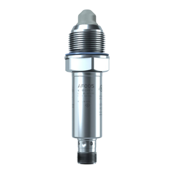
    G 1/2 ist in zwei Varianten verfügbar: Für frontseitige Montage (Abb� 3-1) und für rückwärtige Montage (Abb. 3-2 und → 5.2.2). Tab. 3-1 Voreinstellung Empfindlichkeit Prozessanschluss Abbildung AF005 Wässrige Medien niedrig G 1/2, frontseitig Abb� 3-1 AF006 Wässrige Medien niedrig G 1/2, rückwärtig...
  • Seite 5: 3�2 Beschränkung Des Einsatzbereichs

    All manuals and user guides at all-guides.com 3.2 Beschränkung des Einsatzbereichs • Nicht geeignet für den Hygienebereich� • Nicht geeignet für abrasive Medien (z� B� Quarzsand) und schweres Schüttgut (z� B� Steine)� • Bei Einsatz in aggressiven Medien (Säuren und Laugen): ►...
  • Seite 6: Funktion

    All manuals and user guides at all-guides.com 4 Funktion 4.1 Messprinzip Das Gerät arbeitet nach dem Impedanzspektroskopie- Abb. 4-1 Verfahren� Es analysiert die elektrischen Eigenschaften der zu überwachenden Medien im Frequenzbereich zwischen 50 und 200 MHz� Von der Sondenspitze ausgehend bildet sich ein elektrisches Feld, das durch den Füllstand beeinflusst wird�...
  • Seite 7: 4�3 Anwendungsbeispiele

    All manuals and user guides at all-guides.com 4.3 Anwendungsbeispiele 4.3.1 Anwendungsbeispiele für frontseitige Montage Abb. 4-2 Abb. 4-3 1: Einbausituation bedingt geeignet • Abb� 4-2: Mögliche Einbaupositionen in einem Tank (z� B� für die Grenzstander- fassung oder als Trockenlaufschutz) • Abb� 4-3: Überwachung des Befüllungsgrades in Rohrleitungen� Die Einbaupositionen (1) Abb�...
  • Seite 8: 4�3�2 Anwendungsbeispiele Für Rückwärtige Montage Über Einbaurohr

    All manuals and user guides at all-guides.com 4.3.2 Anwendungsbeispiele für rückwärtige Montage über Einbaurohr Einbau von oben: Abb. 4-4 1: Maximaler Füllstand 2: Minimaler Füllstand 3: Einbaurohr Der Sensor kann rückwärtig in ein Rohr variabler Länge (3) montiert werden� Dadurch sind unterschiedliche Ansprechpunkte realisierbar� Beispiel: Überwachung maximaler Füllstand (1) oder minimaler Füllstand (2)�...
  • Seite 9: Montage

    All manuals and user guides at all-guides.com Seitlicher Einbau: Abb. 4-5 Durch die tiefere Position der Sondenspitze im Behälter können stark anhaftende und zähflüssige Rückstände ausgeblendet werden� 5 Montage Vor Ein- und Ausbau des Geräts: Sicherstellen, dass die Anlage druckfrei ist und sich kein Medium in der Rohrleitung oder dem Behälter befindet�...
  • Seite 10: 5�2 Montagevorgang

    Einbauten, anderen LM-Sensoren) einhalten (Abb� 5-1)� 15 mm 5.2 Montagevorgang 5.2.1 Frontseitige Montage bei AF005 ► Beiliegende Flachdichtung über das Gewinde auf den Sensor aufschieben und/ oder deren Sitz prüfen� ► Gewinde des Sensors mit einer für den vorliegenden Anwendungsbereich geeigneten und zugelassenen Schmierpaste leicht einfetten�...
  • Seite 11: 5�2�2 Rückwärtige Montage Bei Af006

    All manuals and user guides at all-guides.com 5.2.2 Rückwärtige Montage bei AF006 ► Kabeldose (gerade Ausführung) durch das vorgesehene Einbaurohr führen (Abb� 5-2)� ► Beiliegende Flachdichtung über das (rückwärtige) Gewinde auf den Sensor aufschieben/deren Sitz prüfen (Abb� 5-3)� ► Sensor mit Kabeldose verschrauben (Abb� 5-4)� ►...
  • Seite 12: Elektrischer Anschluss

    ► Gerät folgendermaßen anschließen: Adernfarben schwarz OUT2 braun OUT1 blau weiß OUT1: Schaltausgang/IO-Link OUT2: Schaltausgang Farbkennzeichnung nach DIN EN 60947-5-2 Beispielbeschaltungen 2 x p-schaltend 2 x n-schaltend 2: OUT2 2: OUT2 4: OUT1 4: OUT1 Werkseinstellung OUT1 und OUT2: pnp-Schaltsignal� Verfügbares Zubehör: www�autosen�com...
  • Seite 13: Schnittstellen

    Die zur Konfiguration des Gerätes notwendigen IODDs, detaillierte Informationen über Prozessdatenaufbau, Diagnoseinformationen und Parameteradressen sowie alle notwendigen Informationen zur benötigten IO-Link-Hardware und Software stehen unter www�autosen�com zur Verfügung� 8 Parametrierung In der Werkseinstellung ist das Gerät für Wasser und wässrige Medien voreingestellt�...
  • Seite 14: 8�1 Parametrierung Über Pc Und Io-Link Interface

    All manuals and user guides at all-guides.com 8.1 Parametrierung über PC und IO-Link Interface ► Computer, Software und Interface vorbereiten → Bedienungsanleitungen der jeweiligen Geräte / Software beachten (→ 7.1). ► Gerät mit IO-Link Interface verbinden (→ Zubehör). ► Menü der IO-Link Software folgen� ►...
  • Seite 15: 8�2 Parameter

    All manuals and user guides at all-guides.com 8.2 Parameter SPx/rPx Schaltschwellen der Schaltpunkte (SPx) und Rückschaltpunkte (rPx) für Ausgänge OUT1 und OUT2� Die Werte für SPx/rPx werden in Prozent des maximalen Prozesswertes eingestellt� Der Prozesswert definiert sich wie folgt: Prozesswert in Luft = 0 % Prozesswert in Leitungswasser = 100 % Minimale Hysterese: 2 % Art des Mediums:...
  • Seite 16: 8�5 Vollabgleich Durchführen

    All manuals and user guides at all-guides.com 8.4 Vollabgleich durchführen ► Behälter/Rohrleitung befüllen� > Sondenspitze muss vom Medium vollständig bedeckt sein� ► Systemkommando [tSP1] oder [tSP2] durchführen� > Gerät setzt automatisch die Schaltschwellen [SPx]/[rPx]� ► Die Funktion durch einen Applikationstest prüfen� 9 Betrieb Nach Einschalten der Versorgungsspannung befindet sich das Gerät im Arbeitsbe- trieb�...
  • Seite 17: Werkseinstellung

    ► Bei Rücksendungen dafür sorgen, dass das Gerät frei ist von Verunreinigun- gen, insbesondere von gefährlichen und giftigen Stoffen� Für den Transport nur geeignete Verpackungen verwenden, um Beschädigung des Gerätes zu vermeiden� 11 Werkseinstellung AF005/ Benutzer-Einstellung AF006 70 % 62 %...
  • Seite 18 4�3�2 Application examples for rear installation via pipe ������������������������������24 5 Mounting ������������������������������������������������������������������������������������������������������������25 5�1 Installation location / environment ���������������������������������������������������������������25 5�2 Installation procedure ���������������������������������������������������������������������������������26 5�2�1 Front installation for AF005 �����������������������������������������������������������������26 5�2�2 Rear installation for AF006 �����������������������������������������������������������������27 6 Electrical connection ������������������������������������������������������������������������������������������28 7 Interfaces �����������������������������������������������������������������������������������������������������������29 7�1 O-Link communication interface ������������������������������������������������������������������29...
  • Seite 19: Preliminary Note

    All manuals and user guides at all-guides.com 1 Preliminary note 1.1 Symbols used ► Instructions > Reaction, result → Cross-reference Important note Non-compliance may result in malfunction or interference� Information Supplementary note� 2 Safety instructions • Read this document before setting up the product and keep it during the entire service life�...
  • Seite 20: Functions And Features

    G 1/2 is available in two versions: for front installation (Fig� 3-1) and for rear installation (Fig. 3-2 and → 5.2.2). Table 3-1 Type Default value Sensitivity Process connection Figure AF005 Aqueous media G 1/2, front Fig� 3-1 AF006 Aqueous media G 1/2, rear Fig� 3-2 Fig.
  • Seite 21: 3�2 Restriction Of The Application Area

    All manuals and user guides at all-guides.com 3.2 Restriction of the application area • Not suitable for hygienic areas� • Not suitable for abrasive media (e�g� quartz sand) and heavy bulk material (e�g� stones)� • For use in aggressive media (strong acids and alkali): ►...
  • Seite 22: Function

    All manuals and user guides at all-guides.com 4 Function 4.1 Measuring principle The unit operates to the impedance spectroscopy Fig. 4-1 method� It analyses the electrical characteristics of the media to be monitored in the frequency range between 50 and 200 MHz� An electrical field is generated by the probe tip which is influenced by the level�...
  • Seite 23: 4�3 Application Examples

    All manuals and user guides at all-guides.com 4.3 Application examples 4.3.1 Application examples for front installation Fig. 4-2 Fig. 4-3 1: Installation only suited to some extent • Fig� 4-2: Possible installation positions in a tank (e�g� for point level detection or as run-dry protection)�...
  • Seite 24: 4�3�2 Application Examples For Rear Installation Via Pipe

    All manuals and user guides at all-guides.com 4.3.2 Application examples for rear installation via pipe Installation from the top: 1: Maximum level 2: Minimum level 3: Probe Rear installation of the sensor in a pipe of variable length (3) is possible� Different response points can be implemented�...
  • Seite 25: Mounting

    All manuals and user guides at all-guides.com Lateral installation: Since the probe tip is installed further into the tank, very adhesive and viscous residues can be suppressed� 5 Mounting Before installing and removing the unit: Make sure that no pressure is applied to the system and there is no medium in the pipe or the tank�...
  • Seite 26: 5�2 Installation Procedure

    (Fig� 5-1)� 15 mm 5.2 Installation procedure 5.2.1 Front installation for AF005 ► Slide the supplied flat seal over the thread onto the sensor and/or verify its correct position� ► Slightly grease the thread of the sensor using a lubricating paste which is suita- ble and approved for the application�...
  • Seite 27: 5�2�2 Rear Installation For Af006

    All manuals and user guides at all-guides.com 5.2.2 Rear installation for AF006 ► Lay the socket (straight design) through the respective probe (Fig� 5-2)� ► Slide the supplied flat seal over the (rear) thread onto the sensor/verify its position (Fig� 5-3)� ►...
  • Seite 28: Electrical Connection

    OUT1: switching output / IO-Link OUT2: switching output Colours to DIN EN 60947-5-2 Example circuits 2 x positive switching 2 x negative switching 2: OUT2 2: OUT2 4: OUT1 4: OUT1 Factory setting OUT1 and OUT2: pnp switching signal� Available accessories: www�autosen�com...
  • Seite 29: Interfaces

    The IODDs necessary for the configuration of the unit, detailed information about process data structure, diagnostic information, parameter addresses and the necessary information about the required IO-Link hardware and software are available at www�autosen�com� 8 Parameter setting In many cases the factory setting is sufficient For special requirements it is possible to adapt/configure the sensitivity and other functions to the appli- cation�...
  • Seite 30: 8�1 Parameter Setting Via Pc And Io-Link Interface

    All manuals and user guides at all-guides.com 8.1 Parameter setting via PC and IO-Link interface ► Prepare computer, software and interface → Observe the operating instructions for the respective devices / software → 7.1). ► Connect unit with IO-Link interface ( →accessories). ►...
  • Seite 31: 8�2 Parameters

    All manuals and user guides at all-guides.com 8.2 Parameters SPx/rPx Switching thresholds of the set points (SPx) and reset points (rPx) for outputs OUT1 and OUT2� The values for SPx/rPx are set in percent of the max� process value� The process value is defined as follows: Process value in air = 0 % Process value in tap water = 100 %...
  • Seite 32: 8�4 Set To The Full Vessel

    All manuals and user guides at all-guides.com 8.4 Set to the full vessel ► Fill the vessel/pipe� > The probe tip must be completely covered with the medium� ► Execute the system command [tSP1] or [tSP2]� > The unit automatically sets the switching thresholds [SPx]/[rPx]� ►...
  • Seite 33: Factory Setting

    ► In case of returns ensure that the unit is free from soiling, especially of dan- gerous and toxic substances� For transport only use appropriate packaging to avoid damage of the unit� 11 Factory setting AF005/ User setting AF006 70 %...
  • Seite 34 �������������������������������������������������������������������������������������������������40 5 Montage �������������������������������������������������������������������������������������������������������������41 5�1 Lieu de montage / environnement de montage ����������������������������������������������41 5�2 Montage ������������������������������������������������������������������������������������������������������42 5�2�1 Montage frontal en cas de AF005 �������������������������������������������������������42 5�2�2 Montage par l’arrière pour le AF006 ���������������������������������������������������43 6 Raccordement électrique �����������������������������������������������������������������������������������44 7 Interfaces �����������������������������������������������������������������������������������������������������������45 7�1 Interface de communication IO-Link ������������������������������������������������������������45...
  • Seite 35: Remarques Préliminaires

    All manuals and user guides at all-guides.com 1 Remarques préliminaires 1.1 Symboles utilisés ► Action à faire > Retour d'information, résultat → Référence croisée Remarque importante Le non-respect peut aboutir à des dysfonctionnements ou perturbations� Information Remarque supplémentaire� 2 Consignes de sécurité •...
  • Seite 36: Fonctionnement Et Caractéristiques

    G 1/2 est disponible en deux versions : pour montage frontal (Fig� 3-1) et pour montage par l’arrière (Fig. 3-2 et → 5.2.2). Tab. 3-1 Type Réglage par défaut Sensibilité Raccord process Figure AF005 fluides aqueux faible G 1/2, frontal Fig� 3-1 AF006 fluides aqueux faible G 1/2, arrière...
  • Seite 37: 3�2 Restriction De L'application

    All manuals and user guides at all-guides.com 3.2 Restriction de l'application • Pas approprié pour les applications aseptiques� • Pas approprié pour des fluides abrasifs (par ex� sable de quartz) ou des ma- tières en vrac lourdes (par ex� pierres)� •...
  • Seite 38: Fonction

    All manuals and user guides at all-guides.com 4 Fonction 4.1 Principe de mesure L'appareil fonctionne selon la méthode de spec- Fig. 4-1 troscopie d'impédance� Il analyse les caractéristiques électriques des fluides à surveiller dans la gamme de fréquences entre 50 et 200 MHz� Le champ électrique émanant du bout de la sonde est influencé...
  • Seite 39: 4�3 Exemples D'applications

    All manuals and user guides at all-guides.com 4.3 Exemples d'applications 4.3.1 Exemples d'applications pour montage frontal Fig. 4-2 Fig. 4-3 1: Ce montage n'est pas forcément appropriée� • Fig� 4-2: Différentes positions de montage dans une cuve (par ex� pour la détection du niveau limite ou comme anti marche à...
  • Seite 40: 4�3�2 Exemples D'applications Pour Montage Par L'arrière Via Un Tube Prolon

    All manuals and user guides at all-guides.com 4.3.2 Exemples d'applications pour montage par l’arrière via un tube prolon- gateur Montage par le haut : 1: Niveau maximum 2: Niveau minimum 3: Tube prolongateur Le capteur peut être monté par l’arrière sur des tubes de différentes longueurs (3)� Ainsi différents niveaux sont réalisables�...
  • Seite 41: Montage

    All manuals and user guides at all-guides.com Montage latéral : La position éloignée de la cuve permet une détection fiable des fluides très col- matants et visqueux� 5 Montage Avant le montage et le démontage de l'appareil : s'assurer que l'installation est hors pression et qu'il n'y a pas de fluide dans le tuyau ou la cuve�...
  • Seite 42: 5�2 Montage

    LM) (Fig� 5-1)� 15 mm 5.2 Montage 5.2.1 Montage frontal en cas de AF005 ► Monter le joint plat fourni coté filetage du capteur et / ou vérifier son bon posi- tionnement� ► Graisser légèrement le filetage du capteur avec une pâte lubrifiante qui est appropriée et homologuée pour l'application�...
  • Seite 43: 5�2�2 Montage Par L'arrière Pour Le Af006

    All manuals and user guides at all-guides.com 5.2.2 Montage par l’arrière pour le AF006 ► Introduire le connecteur femelle (version droite) au travers du tube prolonga- teur (Fig� 5-2)� ► Monter le joint plat fourni coté filetage du capteur (arrière) et / ou vérifier son bon positionnement (Fig�...
  • Seite 44: Raccordement Électrique

    OUT2 : sortie de commutation Couleurs selon DIN EN 60947-5-2 Exemples de raccordement 2 x commutation positive 2 x commutation négative 2: OUT2 2: OUT2 4: OUT1 4: OUT1 Réglage usine OUT1 et OUT2 : signal de commutation pnp� Accessoires disponibles : www�autosen�com...
  • Seite 45: Interfaces

    IO-Link sont disponibles sur www�autosen�com� 8 Paramétrage Dans la plupart des cas, le réglage usine est suffisant� Pour les applications avec des exigences plus spécifiques, il est également possible d'adapter/...
  • Seite 46: 8�1 Paramétrage Via Pc Et Interface Io-Link

    All manuals and user guides at all-guides.com 8.1 Paramétrage via PC et interface IO-Link ► Préparer l'ordinateur, le logiciel et l'interface → Observez le mode d'emploi des périphériques / logiciels respectifs (--> 7�1)� ► Raccorder l'appareil avec l'interface IO-Link� (-->Accessoires) ►...
  • Seite 47: 8�3 Paramètre

    All manuals and user guides at all-guides.com 8.2 Paramètre SPx/rPx Seuils de commutation de l'enclenchement (SPx) et du déclenchement (rPx) pour les sorties OUT1 et OUT2� Les valeurs pour SPx / rPx sont réglées en pourcent de la valeur pro- cess maximale�...
  • Seite 48: 8�5 Effectuer Le Réglage Plein

    All manuals and user guides at all-guides.com 8.4 Effectuer le réglage plein ► Remplir la cuve/le tuyau� > Le bout de la sonde doit être complètement immergé� ► Effectuer la commande de système [tSP1] ou [tSP2]� > L'appareil règle les seuils de commutation [SPx]/[rPx] automatiquement� ►...
  • Seite 49: Entretien, Réparation Et Élimination

    ► En cas de retour, s’assurer que l'appareil est exempt d'impuretés, en particulier de substances dangereuses et toxiques� Utiliser seulement des emballages appropriés pour le transport afin d'éviter l'endommagement de l'appareil� 11 Réglage usine AF005/AF006 Réglage utilisateur 70 % 62 %...
  • Seite 50 All manuals and user guides at all-guides.com Technische Daten und weitere Informationen unter: Données techniques et informations supplémentaires sur notre site web à: Technical data and further information at: www.autosen.com...

Diese Anleitung auch für:

Af006

Inhaltsverzeichnis