Herunterladen Inhalt Inhalt Diese Seite drucken
autosen AF001 Bedienungsanleitung

autosen AF001 Bedienungsanleitung

Binärer füllstandsensor
Inhaltsverzeichnis

Werbung

Verfügbare Sprachen

Verfügbare Sprachen

Bedienungsanleitung
DE
Binärer Füllstandsensor
UK
Operating instructions
FR
Binary level sensor
Notice d'utilisation
Capteur de niveau TOR
AF001
autosen
Made in Germany

Werbung

Inhaltsverzeichnis
loading

Inhaltszusammenfassung für autosen AF001

  • Seite 1 Bedienungsanleitung Binärer Füllstandsensor Operating instructions Binary level sensor Notice d‘utilisation Capteur de niveau TOR AF001 autosen Made in Germany...
  • Seite 2: Inhaltsverzeichnis

    Inhalt 1 Vorbemerkung ������������������������������������������������������������������������������������������������������3 1�1 Verwendete Symbole �������������������������������������������������������������������������������������3 2 Sicherheitshinweise ����������������������������������������������������������������������������������������������3 3 Bestimmungsgemäße Verwendung����������������������������������������������������������������������4 3�1 Einsatzbereich ������������������������������������������������������������������������������������������������4 3�2 Beschränkung des Einsatzbereichs ���������������������������������������������������������������4 4 Funktion ����������������������������������������������������������������������������������������������������������������4 4�1 Messprinzip ����������������������������������������������������������������������������������������������������4 4�2 Gerätemerkmale ���������������������������������������������������������������������������������������������5 4�3 Anwendungsbeispiele �������������������������������������������������������������������������������������6 5 Montage����������������������������������������������������������������������������������������������������������������6 5�1 Einbauort / Einbauumgebung �������������������������������������������������������������������������6 5�2 Montagevorgang ��������������������������������������������������������������������������������������������7 5�3 Einbaulänge festlegen ������������������������������������������������������������������������������������8 6 Elektrischer Anschluss������������������������������������������������������������������������������������������9...
  • Seite 3: Vorbemerkung

    1 Vorbemerkung 1.1 Verwendete Symbole ► Handlungsanweisung > Reaktion, Ergebnis […] Bezeichnung von Tasten, Schaltflächen oder Anzeigen → Querverweis Wichtiger Hinweis Fehlfunktionen oder Störungen sind bei Nichtbeachtung möglich� Information Ergänzender Hinweis� 2 Sicherheitshinweise • Lesen Sie vor der Inbetriebnahme des Gerätes die Produktbeschreibung� Ver- gewissern Sie sich, dass sich das Produkt uneingeschränkt für die betreffenden Applikationen eignet�...
  • Seite 4: Bestimmungsgemäße Verwendung

    3 Bestimmungsgemäße Verwendung Das Gerät überwacht den Füllstand flüssiger Medien in Behältern� 3.1 Einsatzbereich • Wasser, wasserbasierte Medien, Öle, Kühlschmieremulsionen� 3.2 Beschränkung des Einsatzbereichs • Das Gerät ist nicht geeignet für Säuren, Laugen, Granulate, Schüttgüter� • Es ist nicht geeignet für den Hygienebereich� • Gut leitfähiger Schaum kann zum Schaltvorgang führen�...
  • Seite 5: 4�2 Gerätemerkmale

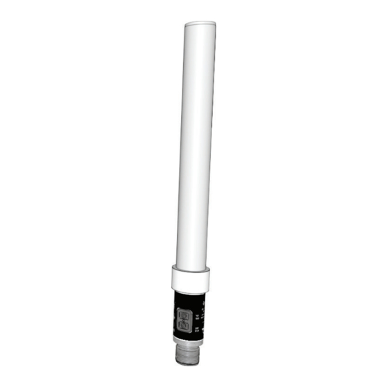
    Das Gerät arbeitet mit radialer Erfas- sungs-Charakteristik� Dadurch wird die Erfassung von Medien unterhalb der Aktiven Zone unterdrückt� Medien wer- den trotz unterschiedlicher elektrischer Eigenschaften erst dann erfasst, wenn die Aktive Zone (A) bedeckt ist� 4.2 Gerätemerkmale • Schließer- oder Öffnerfunktion einstellbar durch Programmiertasten (→ Kapitel 8 Einstellungen).
  • Seite 6: 4�3 Anwendungsbeispiele

    - Wasser, wasserähnliche Medien und Öle in ungeerdetem Kunststoffbehälter: 200 mm� Je nach Applikation können höhere Abstände erforderlich sein� Prüfen Sie dies durch einen Funktionstest unter realen Betriebsbedingungen� Abstand zwischen AF001- und AF002-Geräten: min� 60 mm von Stabmitte zu Stab- mitte�...
  • Seite 7: 5�2 Montagevorgang

    5.2 Montagevorgang Das Gerät wird mit Hilfe einer Klemmschelle oder eines Adapters eingebaut� Folgendes Standard-Montagezubehör ist lieferbar: Bestell-Nr� • Flanschadapter mit Klemmadaption (druckfest bis 0,5 bar) ������������������������������������������AA923 • Flanschadapter mit Klemmadaption (druckfest bis 0,5 bar) ������������������������������������������AA925 • Einbauadapter G¾ mit Klemmadaption (Edelstahl, druckfest bis 0,5 bar) ��������������������AA924...
  • Seite 8: 5�3 Einbaulänge Festlegen

    5.3 Einbaulänge festlegen A = Ansprechhöhe LI51-m1 H = Behälterhöhe SH = Stutzenhöhe L = Stablänge (Sondenstab) L1 = Einbaulänge L2 = Auszugslänge L3 = Montagelänge (mindestens 60 mm) MET = maximale Eintauchtiefe (= Aktive Zone; 31 mm) ► Einbaulänge L1 so wählen, dass die Zone MET mindestens zur Hälfte bedeckt ist, wenn die Ansprechhöhe A erreicht ist, also: L1 = (H - A) + ½...
  • Seite 9: Elektrischer Anschluss

    Anlagen� Spannungsversorgung nach EN50178, SELV, PELV� ► Anlage spannungsfrei schalten� ► Gerät folgendermaßen anschließen: Adernfarben bei autosen-Kabeldosen: 1 = BN (braun), 3 = BU (blau), 4 = BK (schwarz)� Das Gerät ist als Schließer oder Öffner verwendbar; → Kapitel 8 Einstellungen. 7 Bedien- und Anzeigeelemente 1: LED-Ring grün / gelb • grün: Betriebsanzeige...
  • Seite 10: Einstellungen

    8 Einstellungen Vor erster Inbetriebnahme muss der Leerabgleich durchgeführt werden� 8.1 Leerabgleich durchführen Der Leerabgleich stellt das Gerät auf den leeren Behälter und die Einbausituation (z� B� die eingestellte Einbaulänge) ein� Vorangegangene Einstellungen werden gelöscht� ► Behälter entleeren, bis das Medium mindestens 20 mm unterhalb des Stab- endes steht�...
  • Seite 11: 8�4 Gerät Verriegeln / Entriegeln

    ► Behälter entleeren, bis das Medium mindestens 20 mm unterhalb des Stab- endes steht. Ist das Gerät als Schließer abgeglichen (→ 8.1), verlischt die gelbe LED, ist es als Öffner abgeglichen, leuchtet sie auf� ► Wenn das Gerät als Schließer abgeglichen ist: [OUT OFF] drücken und minde- stens 6 s lang gedrückt halten� >...
  • Seite 12: Wartung, Instandsetzung, Entsorgung

    Dielektrizitätskonstante (z� B� Öl / Wasser) sollte das Gerät neu abgeglichen werden� Eine Instandsetzung des Geräts ist nicht möglich� Entsorgen Sie das Gerät nach Gebrauch umweltgerecht gemäß den gültigen nationalen Bestimmungen� 11 Technische Daten und Maßzeichnung Technische Daten und Maßzeichung unter www�autosen�com Weitere Informationen unter www�autosen�com...
  • Seite 13 Contents 1 Preliminary note��������������������������������������������������������������������������������������������������14 1�1 Symbols used �����������������������������������������������������������������������������������������������14 2 Safety instructions ����������������������������������������������������������������������������������������������14 3 Functions and features ���������������������������������������������������������������������������������������15 3�1 Application area ��������������������������������������������������������������������������������������������15 3�2 Restriction of the application area ����������������������������������������������������������������15 4 Function ��������������������������������������������������������������������������������������������������������������15 4�1 Measuring principle ��������������������������������������������������������������������������������������15 4�2 Features of the unit ��������������������������������������������������������������������������������������16 4�3 Application examples ������������������������������������������������������������������������������������17 5 Installation �������������������������������������������������������������������������������������������������������17 5�1 Installation location / environment ����������������������������������������������������������������17...
  • Seite 14: Preliminary Note

    1 Preliminary note 1.1 Symbols used ► Instruction > Reaction, result […] Designation of pushbuttons, buttons or indications → Cross-reference Important note Non-compliance can result in malfunctions or interference� Information Supplementary note� 2 Safety instructions • Please read the product description prior to set-up of the unit� Ensure that the product is suitable for your application without any restrictions�...
  • Seite 15: Functions And Features

    3 Functions and features The unit monitors the level of liquids in tanks� 3.1 Application area • Water, hydrous media, oils, coolant emulsions� 3.2 Restriction of the application area • The unit is not suitable for acids, alkalis, granulates, bulk materials� • It is not suitable for hygienic areas�...
  • Seite 16: 4�2 Features Of The Unit

    The unit operates with radial detection characteristics� Therefore media below the active zone are not detected� Despite different electrical properties media are only detected when the active zone (A) is covered� 4.2 Features of the unit • NO or NC function can be set by programming buttons (→ chapter 8 Settings) - NO function: output closed when the level has been reached / output open when the level has not been reached�...
  • Seite 17: 4�3 Application Examples

    Depending on the application greater distances can be required� Please check this by a function test under real operating conditions� Distance between AF001 and AF002 units: min� 60 mm from the centre of a probe to the centre of another probe�...
  • Seite 18: 5�2� Installation Procedure

    5.2. Installation procedure The unit is mounted using a mounting clamp or an adapter� The following standard mounting accessories are available: Order no� • flange plate with clamp adapter (pressure rating of 0�5 bar) �����������������������������������������AA923 • flange plate with clamp adapter (pressure rating of 0�5 bar) �����������������������������������������AA925 • mounting adapter G¾...
  • Seite 19: 5�3 Set The Installation Length

    5.3 Set the installation length A = response level LI51-m1 H = tank height SH = height of the connection piece L = probe length L1 = installation length L2 = extension length L3 = mounting length (at least 60 mm) MET = maximum installation depth (= active zone;...
  • Seite 20: Electrical Connection

    Voltage supply to EN 50178, SELV, PELV� ► Disconnect power� ► Connect the unit as follows: core colours of autosen sockets: 1 = BN (brown), 3 = BU (blue), 4 = BK (black) The unit can be used as NO or NC unit; → chapter 8 Settings. 7 Operating and display elements 1: LED ring green / yellow • green: operation display...
  • Seite 21: Settings

    8 Settings Before the first set-up the basic teach empty state must be carried out� 8.1 Carry out the basic teach empty state The basic teach empty state sets the unit to the empty tank and the installation conditions (e�g� the set installation length)� Previous settings are deleted� ►...
  • Seite 22: 8�3 Set The Deposit Suppression (Option)

    8.3 Set the deposit suppression (option) This setting largely suppresses deposits in the tank and on the probe� Previous settings are not changed� ► Empty the tank until the medium is at least 20 mm below the end of the probe end. If the unit is set as NO unit (→ 8.1), the yellow LED goes off, if it is set as NC unit, it lights�...
  • Seite 23: Maintenance, Repair And Disposal

    It is not possible to repair the unit� After use dispose of the unit in an environmentally friendly way in accordance with the applicable national regulations� 11 Technical data and scale drawing Technical data and scale drawing at www�autosen�com More information at www�autosen�com...
  • Seite 24 Contenu 1 Remarques préliminaires������������������������������������������������������������������������������������25 1�1 Symboles utilisés ������������������������������������������������������������������������������������������25 2 Consignes de sécurité ����������������������������������������������������������������������������������������25 3 Fonctionnement et caractéristiques��������������������������������������������������������������������26 3�1 Applications ��������������������������������������������������������������������������������������������������26 3�2 Restriction de l'application ����������������������������������������������������������������������������26 4 Fonction ��������������������������������������������������������������������������������������������������������������26 4�1 Principe de mesure �������������������������������������������������������������������������������������26 4�2 Caractéristiques de l'appareil �����������������������������������������������������������������������27 4�3 Exemples d'applications �������������������������������������������������������������������������������28 5 Montage��������������������������������������������������������������������������������������������������������������28 5�1 Lieu de montage / environnement de montage ��������������������������������������������28 5�2 Montage �������������������������������������������������������������������������������������������������������29...
  • Seite 25: Remarques Préliminaires

    1 Remarques préliminaires 1.1 Symboles utilisés ► Action à faire > Retour d'information, résultat […] Désignation d'une touche, d'un bouton ou d'un affichage → Référence Remarque importante Le non-respect peut aboutir à des dysfonctionnements ou perturbations� Information Remarque supplémentaire� 2 Consignes de sécurité • Avant la mise en service de l'appareil, lire la description du produit�...
  • Seite 26: Fonctionnement Et Caractéristiques

    3 Fonctionnement et caractéristiques L'appareil surveille le niveau de liquides dans des cuves� 3.1 Applications • eau, fluides aqueux, huiles, liquides de lubrification 3.2 Restriction de l'application • L'appareil n'est pas approprié pour les acides, bases, fluides pulvérulents, matières en vrac� • Il n'est pas approprié...
  • Seite 27: 4�2 Caractéristiques De L'appareil

    La zone de détection du détecteur est radiale� Cela signifie que des fluides qui se situent en-dessous de la zone active ne sont pas détectés� Quelles que soient leurs caractéristiques élec- triques, les fluides ne sont détectés que si la zone active (A) est couverte� 4.2 Caractéristiques de l'appareil • Fonction normalement ouvert ou fermé...
  • Seite 28: 4�3 Exemples D'applications

    - Eau, fluides aqueux et huiles dans une cuve plastique non mise à la terre : 200 mm� Selon l’application, des distances plus grandes peuvent être nécessaires� Veuillez le vérifier par un test fonctionnel sous des conditions de fonctionnement réelles� Distance entre des détecteurs AF001 et AF002 : min� 60 mm d‘axe à axe des sondes�...
  • Seite 29: 5�2 Montage

    5.2 Montage L'appareil est monté à l'aide d'une bride de fixation ou d'un adaptateur� Les acces- soires de montage standards suivants sont disponibles : Référence • bride à visser avec bague de fixation (tenue en pression de 0,5 bar) ���������������������������AA923 • bride à visser avec bague de fixation (tenue en pression de 0,5 bar) ���������������������������AA925 • doigt de gant G¾...
  • Seite 30: 5�3 Définir La Longueur D'installation

    5.3 Définir la longueur d'installation A = niveau de réponse LI51-m1 H = hauteur de la cuve SH = hauteur de la manchette L = longueur de la sonde L1 = longueur d'installation L2 = longueur d'extension L3 = longueur de montage (au moins 60 mm) MET = profondeur d'installation maximale (= zone active;...
  • Seite 31: Raccordement Électrique

    Alimentation selon EN50178, TBTS, TBTP� ► Mettre l'installation hors tension� ► Raccorder l'appareil comme suit : Couleurs des fils conducteurs des connecteurs femelles autosen : 1 = BN (brun), 3 = BU (bleu), 4 = BK (noir) L'appareil peut être utilisé en fonction normalement ouvert ou normalement fermé ; → chapitre 8 Réglages�...
  • Seite 32: Réglage

    8 Réglage Avant la première mise en service, effectuer le réglage vide� 8.1 Effectuer le réglage vide Le réglage vide permet de régler l'appareil en cuve vide et pour la situation d'installation (par ex� la longueur d'installation réglée)� Des réglages précédents sont effacés�...
  • Seite 33: 8�4 Verrouiller / Déverrouiller L'appareil

    ► Vider la cuve jusqu'à ce que le fluide soit au moins 20 mm en dessous de l'extrémité de la sonde. Si l'appareil est réglé en normalement ouvert (→ 8.1), la LED jaune s'éteint, s'il est réglé en normalement fermé, elle s'allume� ► Si l'appareil est réglé en normalement ouvert : appuyer sur [OUT OFF] et le maintenir appuyé...
  • Seite 34: Entretien, Réparation Et Élimination

    être réglé de nouveau� L'appareil ne peut pas être réparé� S'assurer d'une élimination écologique de l'appareil après son usage selon les règlements nationaux en vigueur� 11 Données techniques et schéma d‘encombrement Données techniques et schéma d’encombrement à www�autosen�com Plus d'informations à www�autosen�com...
  • Seite 36 Technische Daten und weitere Informationen unter: Données techniques et informations supplémentaires sur notre site web à: Technical data and further information at: www.autosen.com...

Inhaltsverzeichnis