entrematic Ditec Smart Plus Handbuch Die Montage, Wartung, Bedienung

Inhaltszusammenfassung für entrematic Ditec Smart Plus
- Seite 1 0DT826 Ditec Smart Plus rev. 2014-06-13 Handbuch die montage, wartung, bedienung. (Original Anleitung) Installation manual, maintenance, use. (Original instructions) www.ditecentrematic.com...
-
Seite 2: Inhaltsverzeichnis
Art ohne spezifische Genehmigung des Herstellers durchgeführt werden. Bei Reparatur und Austausch sind ausschließlich Originalersatzteile Entrematic Group AB zu verwenden. Der Einbaubetrieb ist verpflichtet, dem Benutzer alle notwendigen Informationen für Automatik-, Hand- und Notbetrieb des Torantriebs zu liefern und ihm die Betriebanleitung auszuhändigen. -
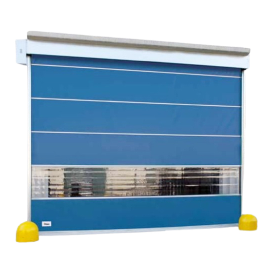
Seite 3: Beschreibung
Rif. Beschreibung Rif. Beschreibung Seitliche Endverschlüsse Getriebemotor K22 / K26 Laufschiene Vorrichtung für manuellen Betrieb Laufschienenabdeckung Stange für manuellen Betrieb Wickelwelle Elektronische Steuerung Kontaktleiste Lichtschranke LAB4 Stütze Aluminiumprofil Stützenabdeckung Sektor Torbehang aus Polyester Dichtung Sektor Torbehang aus transparentem PVC 2. TECHNISCHE MERKMALE ELEKTRONISCHE SCHALTTAFEL DREIPHASEN (48E)(49E) ELEKTRONISCHE SCHALTTAFEL (INVERTER) Spannungsversorgung .. -
Seite 4: Mechanische Installation Der Struktur Und Der Bauteile
3. MECHANISCHE INSTALLATION DER STRuKTuR uND DER BAuTEILE Siehe die entsprechenden Zeichnungen für die mechanische Installation auf Seite 24 - 25 (das mittlere Blatt lässt sich herausnehmen) 3.1 Überprüfungen des Durchgangs (Abb.1). • Die Abmessungen des Durchgangs mit den Außenmaßen des gelieferten Tors vergleichen. Bei Installation in der lichten Durchgangsbreite die eventuell erforderlichen Toleranzen berücksichtigen. -
Seite 5: Elektrische Anschlüsse
4. ELEKTRISCHE ANSCHLÜSSE 4.1 Elektrischer Schaltschrank • Die Kabel mit vorverkabelten Klemmleisten in den Behälter einführen und an die Karten anschließen (Abb.14). Kabel in den Kabelkanal einführen und auf dem Motor vorgesehene Steckverbinder anschließen (Abb.15). 4.2 Anschlüsse Schaltkasten / Motor / Schutzvorrichtungen •... -
Seite 6: Elektronische Schalttafel 5.1 48E - K22 Anschlüsse
5.1 ELEKTRONISCHE SCHALTTAFEL 48E - ANSCHLÜSSE EINGANG Commande Funktion Beschreibung N.O Automatische Die permanente Schließung des Kontaktes aktiviert die automatische Öffnung. Schließung N.O Öffnung Bei DIP1=ON wird beim Schließen des Kontaktes eine Öffnung ausgelöst. Schrittbetrieb Bei DIP1=OFF wird beim Schließen des Kontaktes eine Öffnung oder Schließung in folgender Reihenfolge ausgelöst: Öffnet-Stopp-Schließt-Öffnet. - Seite 7 EL07L By-pass 0000000000000 Lichtschranke www.ditec.it Weiß Endschalter Öffnen Endschalter Schwarz Schließen Blau Stopp Vom Installateur fertigzustellender Anschluss Gelb/Grün Bremse Braun Schwarz U W V RP TC Grau Weiß 1 2 3 4 5 6 - LK + Weiß POWER 17 14 12 11 0 0 0 1 1 2 3 4 6 8 9 20 41 1-9 Schließen: Funktion mit impulsivem Orange...
-
Seite 8: Einstellungen Und Anzeigen
1-9 schaltet sich die automatische Schließung erst nach einem Befehl für die totale Öffnung, die teilweise Öffnung oder die Öffnung im Schrittbetrieb ein. Einstellung teilweise Öffnung Motor. Von 0 bis 30 s. 30 s Dip-switch Beschreibung Für Ditec Smart Plus die Dip-Switch wie folgt DIP 1 Funktion Befehl 1-3. Schrittbetrieb. Öffnung. -
Seite 9: Einstellung Endschalter
EL07L 0000000000000 www.ditec.it U W V RP TC 1 2 3 4 5 6 - LK + POWER 1 7 14 12 1 1 0 0 0 1 1 2 3 4 6 8 9 20 41 SICHERuNGEN Werte Größe Schaltkreis F1 - F2 - F3 8A - 500V... -
Seite 10: K26 Anschlüsse
1-9 schaltet sich die automatische Schließung erst nach einem Befehl für die totale Öffnung, die teilweise Öffnung oder die Öffnung im Schrittbetrieb ein. Einstellung teilweise Öffnung Motor. Von 0 bis 30 s. 30 s Dip-switch Beschreibung Für Ditec Smart Plus die Dip-Switch wie folgt DIP 1 Funktion Befehl 1-3. Schrittbetrieb. Öffnung. - Seite 11 Weiß Endschalter Öffnen EL07L 00000000000 EL07PW1 Endschalter Schwarz 00000000000 Schließen www.ditec.it Blau Stopp Gelb/Grün Vom Installateur Bremse fertigzustellender Anschluss Braun Schwarz RP TC Grau Weiß 1 2 3 4 5 6 - LK + POWER 17 14 12 11 0 0 0 1 1 2 3 4 6 8 9 20 41 Braun 1-9 Schließen: Weiß...
-
Seite 12: Elektronische Schalttafel 47E (Inverter) - Anschlüsse
5.3 ELEKTRONISCHE SCHALTTAFEL 47E (INVERTER) - ANSCHLÜSSE Die Drahtbrücke J2 am Tor Ditec Smart Plus immer trennen EINGANG Befehl Funktion Beschreibung N.O Automatische Die permanente Schließung des Kontaktes aktiviert die automatische Schließung Öffnung. N.O Öffnung Wird beim Schließen des Kontaktes eine Öffnung ausgelöst. - Seite 13 K22 inv Y Endschalter Braun Verzögerung +F -F U V W Weiß Endschalter Öffnen Endschalter Schwarz Schließen Blau Stopp Gelb/Grün Bremse Braun Schwarz P 2.0 OUT1 Grau IN 1 Weiß OFF 1 2 3 4 1 11 12 13 41 40 20 9 8 4 3 2 1 1 0 LAMP SOFA1 Blau 230 V 50/60 Hz...
- Seite 14 EINSTELLuNGEN uND ANZEIGEN Trimmer Beschreibung Zeiteinstellung der automatischen Schließung. Von 0 bis 30 s. 30 s Einstellung teilweise Öffnung. Von 0 bis 10 s. 10 s Einstellung der Öffnungsgeschwindigkeit. Einstellung der Schließgeschwindigkeit. Einstellung der Öffnungsverzögerung. Einstellung der Schließverzögerung. Dip-Switch Beschreibung DIP 1 Aktiviert Trimmer Einstellung Deaktiviert...
- Seite 15 Die Drahtbrücke J2 am Tor Ditec Smart Plus immer trennen +F -F U V W OFF 1 2 3 4 1 11 12 13 41 40 20 9 0 LAMP 230 V 50/60 Hz SICHERuNGEN Werte Größe Schaltkreis F1 - F2 12A - 500V 10.3 x 38...
-
Seite 16: Überprüfung Und Start
6. ÜBERPRÜFuNG uND START 6.1 uberprüfung der Bewegungsrichtung • Torbehang auf zirka die Hälfte der Höhe bringen. • Tor bewegen durch Drücken der entsprechenden Tasten, und Bewegungsrichtung überprüfen. • Nötigenfalls Bewegungsrichtung durch Änderung der Phasensequenz korrigieren. Dazu werden 2 Phasen vertauscht. 6.2 Einstellung der Drahtrippe •... -
Seite 17: Störungssuche
Die folgenden Anweisungen richten sich ausschließlich an qualifiziertes und befugtes Personal. Die ACHTuNG spezifischen Gesetze und Normen müssen immer befolgt werden, auch wenn nicht ausdrücklich darauf hingewiesen wird. Für Reparaturen oder Austausch von Bauteilen immer nur Entrematic Group AB Originalteile verwenden. BEFEHL PROBLEM ÜBERPRÜFuNG... -
Seite 18: Wartungsplan
8. WARTuNGSPLAN (ALLE 6 MONATE) Es empfiehlt sich regelmäßig Überprüfungen durch einen qualifizierten und befugten Techniker Entrematic Group AB entsprechend den nationalen Vorschriften und den Angaben in den Produktunterlagen vornehmen zu lassen. Die Anzahl der Wartungseingriffe sollte in Übereinstimmung mit den nationalen Anforderungen und entsprechend den Angaben in den Produktunterlagen festgelegt werden. -
Seite 19: Allgemeine Sicherheitshinweise
Anlage übertragen werden. Der obengenannte Antrieb ist ein “Tor mit Senkrechtbewegung (Rolltor)” und ist für den Gebrauch für den Sie ausdrücklich hergestellt wurde, bestimmt. Jeder andere Gebrauch wird als Mißbrauch angesehen und ist daher gefährlich. Entrematic Group AB lehnt jede Verhaftung für Schäden, die aufgrund einer missbräuchlichen Verwendung entstanden sind, ab. - Seite 20 8. WARTuNGSPLAN (ALLE 6 MONATE) Es empfiehlt sich regelmäßig Überprüfungen durch einen qualifizierten und befugten Techniker Entrematic Group AB entsprechend den nationalen Vorschriften und den Angaben in den Produktunterlagen vornehmen zu lassen. Die Anzahl der Wartungseingriffe sollte in Übereinstimmung mit den nationalen Anforderungen und entsprechend den Angaben in den Produktunterlagen festgelegt werden.
-
Seite 21: Konformitätserklärung
EN 60204-1 Sonstige angewendete Normen oder technische Spezifikationen: EN 60335-2-103 Die nachstehende benannte Stelle (für die komplette Anschrift kontaktieren Sie bitte die Entrematic Group AB) hat die Typ-Prüfbescheinigung für die gegenständliche Vorrichtung ausgestellt: CSI Spa Reg. - N° 0497 Bescheinigungsnummer: DE/050/05 Der Produktionsprozess gewährleistet die Konformität der Vorrichtung mit der technischen Akte. - Seite 22 - 22 - 0DT826 2014-06-13...
- Seite 23 BAuTEILLISTE Bezug Beschreibung Menge Linke Stütze Rechte Stütze Wickelwelle Kontaktleiste Motor K22 - K26 Schaltkreis Schachtel für das Zubehör - 23 - 0DT826 2014-06-13...
-
Seite 24: Zeichnungen Für Die Mechanische Installation
ZEICHNuNGEN FÜR DIE MECHANISCHE INSTALLATION LT = ( PL + 430 ) ~ 1000 80 STOP M4x8 Ø9 C NO Ø24 Ø5 Ø5 Ø24 ≥ 1,8m... - Seite 25 MECHANICAL INSTALLATION DRAWINGS X=Y± 10mm 1/2H L = (PL+160) STOP 0 COM C NO...
- Seite 48 Entrematic Group AB Lodjursgatan 10 SE-261 44, Landskrona Sweden www.ditecentrematic.com...