Massoth eMotion XL Bedienungsanleitung
Inhaltsverzeichnis
Verfügbare Sprachen
Verfügbare Sprachen
Kapitel
Inhaltsverzeichnis

Verwandte Anleitungen für Massoth eMotion XL


Inhaltszusammenfassung für Massoth eMotion XL
- Seite 1 All manuals and user guides at all-guides.com...
- Seite 2 all-gui des.c...
-
Seite 3: Inhaltsverzeichnis
- Urheberrechte Sicherheitsrelevante und Allgemeine Informationen Sehr geehrter Kunde, mit dem Kauf des eMOTION XL Lokdecoders haben Sie sich für einen beson ders leistungsfähigen Decoder der Massoth Elektronik GmbH entschieden. Wir empfehlen, diese Produktdokumentation gründlich zu lesen, bevor Sie den neuen Lokdecoder in Betrieb nehmen. Die neuesten Entwicklungs- und Fertigungsstandards wurden bei der Entwicklung des eMOTION XL Lokdecoders eingesetzt. -
Seite 4: Wichtige Informationen Zur Inbetriebnahme
All manuals and user guides at all-guides.com normen sind für den großen eMOTION XL Lokdecoder kein Problem: Durch den Einsatz modernster Flash-Technologie kann der Decoder jederzeit über das Gleis auf den neuesten Stand gebracht werden. Dieser Lokdecoder entspricht den CE Konformitätsrichtlinien für elektrische Kleingeräte in der aktuellen Fassung... -
Seite 5: Eigenschaften Des Decoders
All manuals and user guides at all-guides.com Eigenschaften des Decoders Die Eigenschaften des eMOTION XL Lokdecoders im Überblick: 14, 28 und 128 Fahrstufen 256 interne Fahrstufen 10239 Lokadressen programmierbare Fahrkurve Anfahr-, Mittel- und Höchstgeschwindigkeit (sowie Verzögerungszeiten) serielle und parallele Steuerung für alle Licht- und Funktionsausgänge incl. -
Seite 6: Unterstützte Programmiervarianten
All manuals and user guides at all-guides.com Unterstützte Programmiervarianten CV Lesen CV Schreiben CV bitweise Schreiben CV indirekt (mittels Registerprogrammierung für ältere Digitalsyteme) direkte Registerprogrammierung (CV 1 – CV4) POM – Program on Main (Programmieren auf dem Fahrgleis) Kurze Einführung in das Thema Digital Der Vorteil einer Digitalsteuerung liegt in der individuellen Steuerung aller auf dem Gleis befind- lichen Lokomotiven. -
Seite 7: Grundeinstellung
Digitalsystem ein, das mehr als 14 Fahrstufen unterstützt, so kann die Anzahl der Fahrstufen in CV29 geändert werden. Die Erkennung der Fahrbefehle für 128 Fahrstufen geschieht im eMOTION XL Lokdecoder automatisch. Hier ist eine Einstellung nicht notwendig. Grundeinstellung In kurzer Übersicht werden hier die wichtigsten Grundeinstellungswerte des Decoders gezeigt, wie... - Seite 8 all-gui des.c...
-
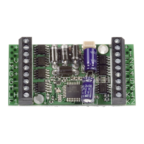
Seite 9: Anschlussschema
All manuals and user guides at all-guides.com Anschlussschema Der eMOTION XL Lokdecoder verfügt über zwei robuste, symetrisch angeordnete Schraubklemmen mit je neun Kontakten. Über diese Klemmen werden alle Verbindungen hergestellt. Die Belegung der Klemmen ist in der folgenden Abbildung Nr. 1 dargestellt. -
Seite 10: Einbau Des Decoders (Schematische Darstellung)
All manuals and user guides at all-guides.com Einbau des Decoders (Schematische Darstellung) Für den Anschluss des eMOTION XL Lokdecoders an ein Getriebe bzw. Motor benötigen Sie vier Kabel mit fertig konfektionierten Faltsteckern, in den Farben gelb, weiß, braun und grün. Zwei Kabel (weiß... -
Seite 11: Einbau In Loks Mit Lgb Schnittstelle
All manuals and user guides at all-guides.com Einbau in Loks mit LGB Decoder-Schnittstelle Mit dem LGB Schnittstellenkabel kann der Decoder zusätzlich an LGB Loks mit Decoderschnittstelle eingebaut werden. Über dieses Kabel können die Licht- und Soundfunktionen der Lok gesteuert werden. Das LGB Schnittstellenkabel ist unter der Artikelnummer 55026 des LGB Sortiments erhält lich. -
Seite 12: Einbau In Loks Mit Lgb Dcc Schnittstelle
Abb. 7: Anschluss des Decoders an die LGB DCC Schnittstelle Einbau in Loks mit Aristocraft DCC Schnittstelle Der Einbau des eMOTION XL Lokdecoders ist auch in ARISTOCRAFT Loks möglich. Dabei kann auch die ARISTOCRAFT DCC Schnittstelle genutzt werden. Die Motorendstufe des eMOTION XL Lokdecoders leistet dauerhaft bis zu 3 Ampere, das reicht in der Regel für 2 Motoren aus. -
Seite 13: Programmieren Des Decoders
All manuals and user guides at all-guides.com Programmieren des Decoders Der eMOTION XL Lokdecoder unterstützt alle üblichen Programmierverfahren nach NMRA / DCC. Beachten Sie bei der Decoderprogrammierung, dass nicht alle genannten Programmiervarianten von allen Digitalsystemen unterstützt werden. Die Anleitung Ihres Digitalsystems sollte hier de... - Seite 14 all-gui des.c...
-
Seite 15: Registerprogrammierung / Cv Indirekt Schreiben
Registerprogrammierung / CV Indirekt Schreiben Die Registerprogrammierung war die erste Programmiervariante, die zum Einstellen der Deco dereigenschaften genutzt wurde. Auch der eMOTION XL Lokdecoder unterstützt dieses Verfahren. Dabei werden die zu programmierende CV und der Wert in Hilfsvariablen gespeichert. Der Decoder führt anschließend die Programmierung der Daten in der entsprechenden CV selbst durch. - Seite 16 All manuals and user guides at all-guides.com Aktuelle Digitalsysteme (z.B. das DiMAX-System) bieten eine komfortable Programmierung der Adresse. Alle CV's einschließlich CV29 werden bei der Option Lokadressenprogrammierung automatisch berechnet und programmiert. Im Auslieferungszustand ist im Decoder generell die Lokadresse 3 programmiert. Mittels der Resetfunktion des Decoders wird auch die Lokadresse 3 wieder aktiviert.
- Seite 17 All manuals and user guides at all-guides.com • Die mittlere Geschwindigkeit (CV6) legt fest, welche Geschwindigkeitsschritte die Lok hat. Wenn in CV6 der halbe Wert von CV5 steht, sind alle Fahrstufen gleichmäßig verteilt. Ist CV6 kleiner als die Hälfte von CV5, werden die unteren Fahrstufen gestreckt. Die Lok fährt dann bei mittlerer Geschwindigkeit langsamer, es ergibt sich ein gedehnter Langsamfahrbereich.
- Seite 18 All manuals and user guides at all-guides.com Programmierbare Sonderfunktionen • Rangiergang : Auf eine frei programmierbare Funktionstaste kann ein Rangiergang gelegt werden. Bei CV59=0 ist die Funktion deaktiv, bei Werten von 1..16 wird die enstprechende Funktionstaste zugeordnet. Bei Auslösung dieser Funktion wird die aktuelle Geschwindigkeit der Lok halbiert.
- Seite 19 All manuals and user guides at all-guides.com Analogbetrieb • Der Betrieb im Analogbetrieb kann mit CV29 - Bit2 gesperrt werden (Wichtig bei Anschluß eines Spannungspuffers) • Der Decoder besitzt eine interne Motorkennlinie, welche mittels Gleisspannungsmessung ein weiches Anfahren im Analogbetrieb ermöglicht. Eine analoge Lastregelung ist zuschaltbar (CV49-Bit2).
- Seite 20 all-gui des.c...
- Seite 21 Nur aktiv, wenn CV29, Bit5 = 1 10239 18 Lange Lokadresse (tiefes Byte) 29 Konfigurations-Register NMRA Siehe Anhang 1 49 Konfigurationsregister Massoth Siehe Anhang 2 50 Licht : Dimmwert (PWM) 1 .. 32 32= volle Gleisspannung 51 Licht-Vorne : Schaltbefehlszuordnung...
- Seite 22 All manuals and user guides at all-guides.com Beschreibung Default A Bereich Bemerkung 53 F1+F2 : Dimmwert Siehe Anhang 4 54 F1 : Schaltbefehlszuordnung Siehe Anhang 3 55 F1 : Sonderfunktionen Siehe Anhang 5 56 F2 : Schaltbefehlszuordnung Siehe Anhang 3 57 F2 : Sonderfunktionen Siehe Anhang 5 + 5a 58 Pausenzeit bei Halt mit Richtungswechsel...
- Seite 23 Nur Digitalbetrieb Digital + Analogbetrieb Interne Fahrkurve Programmierbare Fahrkurve CV 67-94 Kurze Lokadresse (CV1) Lange Adresse CV17+18) Anhang 2: (CV49) – Massoth-Config (bitweise Programmierung, siehe auch Seite 15) Wert Aus (0) Verwendung An (Wert) Bemerkung Nur parallele Serielle + Parallele Funktionsausw. Seriell / Paralell wird...
- Seite 24 All manuals and user guides at all-guides.com Anhang 4: (CV53, 112) - Dimmwerte Wert Verwendung Bemerkung 1 - 32 Prozentuale Spannung am Ausgang Gewünschte Zuordnung muß aufaddiert (32 = volle Spannung) werden ! + 64 Nur F1 (F3) wird gedimmt F1 in CV53 , F3 in CV112 + 128 Nur F2 ( F4) wird gedimmt...
-
Seite 25: Garantie Und Gewährleistungsansprüche
6, 8, 10, 13, 16, 19, 22, 26, 31, 36, 42, 48, 54, 60, 68, 76, 84, 92, 102, 112, 124, 136, 152, 168, 188, 208, 228, 232 Garantie und Gewährleistungsansprüche Massoth garantiert die Fehlerfreiheit dieses Produkts für ein Jahr. Darüberhinaus besteht in Deutschland ein Gewährleistungsanspruch von 2 Jahren. Verschleißteile sind von der Garantieleis... - Seite 26 all-gui des.c...
-
Seite 27: Urheberrechte
Diese Anleitung, alle eingebunden Zeichnungen und Texte sind urheberrechtlich geschützt und dürfen ohne schriftliche Genehmigung nicht weiterverwendet oder dupliziert werden. MASSOTH® und DiMAX® sind eingetragene Warenzeichen der Massoth Elektronik GmbH, See heim, Deutschland. LGB® ist eingetragenes Warenzeichen des Ernst Paul Lehmann Patentwerks,...