Massoth eMOTION XL II PluG Bedienungsanleitung
Inhaltsverzeichnis
Quicklinks
Inhaltsverzeichnis

Verwandte Anleitungen für Massoth eMOTION XL II PluG


Inhaltszusammenfassung für Massoth eMOTION XL II PluG
- Seite 1 XL II PluG Lokdecoder eMOTION XL II PluG Loco Decoder 8150101...
- Seite 2 Warnhinweise vor der Inbetriebnahme notes thoroughly before installing and gründlich zu lesen und diese zu Beachten. operating your decoder. Massoth is not Für Schäden durch Nichtbeachtung der Hin- responsible for any damage if this manual weise übernimmt Massoth keine Haftung.
-
Seite 3: Beschreibung (Funktionsumfang)
1.1 Beschreibung (Funktionsumfang) 1.1 Description Der eMOTION XL II PluG (Summary of Functions) Lokdecoder ist speziell für die The eMOTION XL II PluG Decoder PluG Schnittstelle optimiert is especially designed for the und unterstützt den gesamten PluG Interface and offers the full Funktionsumfang der Schnittstel- range of interface specifications. -
Seite 4: Lieferumfang
• reset function for all CV values 1.2 Lieferumfang 1.2 Scope of Supply • eMOTION XLII Plug Decoder • eMOTION XL II Plug Decoder • eMOTION PluG Schnittstelle • eMOTION PluG Interface (abhängig vom Lieferumfang) (depends on scope of supply) • Bedienungsanleitung... -
Seite 5: Einbauhinweise
Einbau und Anschluss Installation and Connection 2.1 Einbauhinweise 2.1 Installation notes Bauen Sie den Decoder sorgfältig Install your decoder in compliance nach diesen Anschlussplänen ein. with the connecting diagrams Der Decoder ist generell gegen in this manual. The decoder is Kurzschlüsse oder Überlastung protected against shorts and gesichert. -
Seite 6: Anschluss
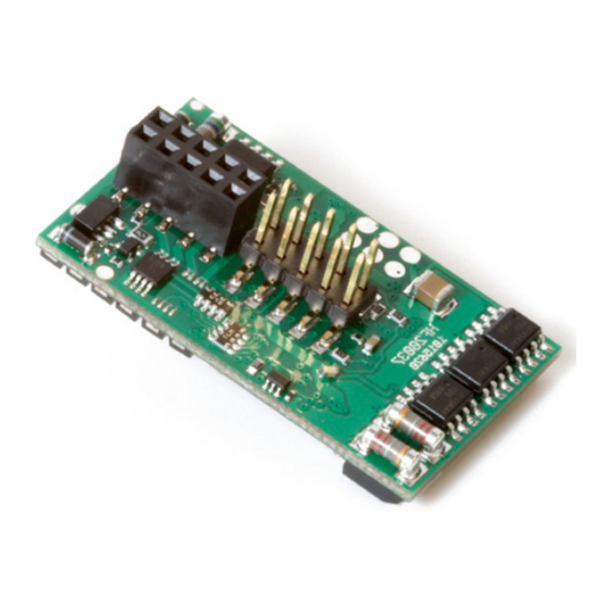
Ende dieser Anleitung. found at the end of this manual. Pin 30 Pin 11 Bild: eMOTION XL II PluG Decoder mit markiertem Pin 11 (entspricht Belegung der Schnittstelle) Illustration: eMOTION XL II PluG Decoder with indexed pin 11 (corresponding to the interface) -
Seite 7: Grundeinstellung
Inbetriebnahme und Getting started, Basic Settings Grundeinstellung This decoder comes with the fol- Dieser Decoder wird ab Werk mit lowing standard factory settings. der folgenden Grundeinstellungen This allows an immediate decoder ausgeliefert. Eine erste Inbetrieb- operation. A detailed configura- nahme ist damit schnell möglich, tion is usually required to set the eine Anpassung jedoch meist decoder to the desired operation... -
Seite 8: Programmierung
Programmierung Programmierung 4.1 Hinweise zur Programmierung 4.1 Programming Notes Dieser Decoder unterstützt die This decoder supports the follow- folgenden Programmierarten: CV ing programming modes: CV write, lesen + schreiben, Register, POM. CV read, Register, POM WICHTIGE HINWEISE ZUR IMPORTANT NOTES FOR PROGRAMMIERUNG PROGRAMMING • Wird der eMOTION XL II Deco-... - Seite 9 Wird CV 16 geändert, ändert sich identical decoders are installed the automatisch CV15. So ist es je- standard value CV 16 needs to be derzeit möglich CV Werte auch im changed. CV 15 will automatically eingebauten Zustand mit anderen be changed to the new value of Decodern zu ändern.
-
Seite 10: Locomotive Address
Einstellungen Settings Es gibt einige CVs, die besonders Some CVs of special importance wichtig sind und richtig eingestellt require a correct setting for prop- sein sollten, damit ein einwandfrei- per operation which are explained er Betrieb sichergestellt ist. Einige in the following chapter. Please CVs werden hier kurz aufgegriffen. - Seite 11 5.3 Fahreigenschaften 5.3 Driving Characteristics • Das Fahrverhalten lässt sich über • The driving characteristics can be diverse CVs beeinflussen, z.B.: adjusted with several CVs, e.g.: - Anfahrspannung (CV 2) - Starting voltage (CV 2) - Beschleunigen (CV 3, CV 4) - Acceleration time (CV 3, CV 4) - max.
-
Seite 12: Funktionen
• Marslight (A5) • Marslight (A5) an- und abschwellendes Licht oscillating light beam • Single strobe • Single strobe einfacher Lichtblitz, Sekundentakt single flash every second • Double strobe • Double strobe doppelter Lichtblitz, Sekundentakt double flash every second • Entkuppler • Uncoupler Anschluss für Massoth-Entkuppler connector for Massoth uncouplers... -
Seite 13: Invertierung
Invertierung: Inversion: • Inverser Ausgang • Output inversion Funktion wird invertiert wenn aktiv If activated, function is inverted (nur bei Servobetrieb möglich) (only for servo operation) Dimmwert (PWM): Dimming (PWM): Alle Funktionsausgänge können All function outputs can be dim- prozentual (0%... 100%) gedimmt med (0%... -
Seite 14: Servo Function
5.5 Servofunktion 5.5 Servo Function Die Ausgänge A7 + A8 können zur The outputs A7 + A8 may operate direkten Steuerung eines Servos servos directly. The servo end genutzt werden. Die Endwerte points may be programmed is re- sind im gültigen Servobereich frei quired. - Seite 15 5.7 Busschnittstelle (CV 49 Bit 4) 5.7 Bus interface (CV 49 Bit 4) Über die Busschnittstelle des The bus interface offers sound Decoders kann ein Soundmodul module operation via SUSI per SUSI angesteuert werden. interface. 5.8 Pufferbetrieb (CV 47) 5.8 Buffer Operation (CV 47) Wird an der PluG-Schnittstelle ein If a power buffer is connected to Pufferspeicher betrieben, kann...
-
Seite 16: Warranty & Customer Service
Kondenswasserbildung zu sufficient to prevent condensed verhindern. water. 6.1 Garantie & Kundendienst 6.1 Warranty & Customer Service MASSOTH gewährt die Fehler- MASSOTH warrants this product freiheit dieses Produkts für ein against defects in materials and Jahr. Die gesetzlichen Regelungen workmanship for one year from können in einzelnen Ländern ab-... - Seite 17 Für Schäden durch unsachgemäße send it directly to the manufac- Behandlung oder Fremdeingriff turer. Return shipping charges are oder Veränderung des Produkts not covered by MASSOTH. Please besteht kein Garantieanspruch. Der include your proof of purchase Anspruch auf Serviceleistungen with the returned goods.
- Seite 18 Zeitfunktion asym. kurz Zeitfunktion asym. lang Monoflop Einschaltverzögerung Kesselfeuer TV flackern Fotograf/Blitzlicht Petroleum flackern Leuchtstoffröhre Start Marslight Single Strobe Double Strobe/Graylight Servofunktion Fahrstufen-Servo MASSOTH Entkuppler Taktgeber Auf-/Abdimmen PWM-Regelung Inverser Ausgang Z: Zeitwert erforderlich, D: Dimmen möglich, *: In Kombination mit dimmbaren Funktionen...
- Seite 19 Petroleum flickering Flourescent tube Marslight Single strobe Double Strobe servo function servo speed step control MASSOTH Uncoupler Clock (Hall Sensor) Fade In / Out Dimming (PWM) Inverted function T: time period required, D: Dimming available; *: In combination with dimmable functions...
- Seite 20 CV - Tabelle Standardeinstellungen. (S = Standard, A = Analogbetrieb) Konfigurationsvariablen (CV-Tabelle) CV Beschreibung A Bereich Bemerkung Lokadresse (standard kurz) 1...127 wenn CV 29, Bit 5 = 0 Anfahrspannung 1...255 CV2 x (1/255 Gleisspannung) Anfahrverzögerung √ 1...255 CV3 x 2ms x (1/255 Gleissp.) Bremsverzögerung √...
- Seite 21 CV - Table Standard settings of the 8FS-decoder. (D = Default, A = analog operation) Table of configuration variables (CV table) CV Description Range Note Loco address (standard short) 1...127 if CV 29 bit 5 = 0 Starting voltage 1...255 CV 2 x (1/255 track voltage) Acceleration time √...
- Seite 22 Fahrkurve (CV 67-94) Bit 5 kurze Lokadresse (CV 1) lange Lokadresse (CV 17/18) 30 Händlersperre 47 Puffernachlaufzeit √ 1...250 1Sek. pro Wert 49 MASSOTH Konfiguration √ bitweise Programmierung Wert AUS (Wert 0) Bit 1 Digitale Lastregelung = AUS Digitale Lastregelung...
- Seite 23 Bit 5 short address (CV 1) long address (CV 17/18) 30 Retailer Lock 47 Buffer runtime √ 1...250 1sec per value 49 MASSOTH Configuration √ bitwise programming Wert OFF (Value 0) Bit 1 Digital Load Control = OFF Digitale Lastregelung...
- Seite 24 Konfigurationsvariablen (CV-Tabelle) CV Beschreibung A Bereich Bemerkung 112 A1: Dimmwert / Servofunktion 100 √ siehe Anhang 2 113 A1: Bedingungen √ siehe Anhang 3 115 A1: Sonderfunktion √ siehe Anhang 4 116 A1: Zeitwert für Sonderfunktion 10 √ 1...250 Zeitbasis 0,1s pro Wert 120 A2: Schaltbefehlszuordnung A siehe Anhang 1 122 A2: Dimmwert / Servofunktion...
- Seite 25 Table of configuration variables (CV table) CV Description Range Note 112 A1: Dimming / Servo function 100 √ see attachment 2 113 A1: Condition √ see attachment 3 115 A1: Special function √ see attachment 4 116 A1: time period for special function 10 √ 1...250 time base 0,1sec.
- Seite 26 Konfigurationsvariablen (CV-Tabelle) CV Beschreibung A Bereich Bemerkung 170 A7: Schaltbefehlszuordnung A siehe Anhang 1 172 A7: Dimmwert / Servofunktion 121 √ siehe Anhang 2 173 A7: Bedingungen √ siehe Anhang 3 175 A7: Sonderfunktion √ siehe Anhang 4 176 A7: Zeitwert für Sonderfunktion 10 √...
- Seite 27 Table of configuration variables (CV table) CV Description Range Note 170 A7: Command allocation A see attachment 1 172 A7: Dimming / Servo function 121 √ see attachment 2 173 A7: Condition √ see attachment 3 175 A7: Special function √ see attachment 4 176 A7: time period for special function 10 √...
-
Seite 28: Anhang 1: Cv 50, 55, 110, 120, 130, 140, 150, 160, 170, 180 - Schaltbefehle
Anhang 1: CV 50, 55, 110, 120, 130, 140, 150, 160, 170, 180 - Schaltbefehle Wert Verwendung Bemerkung 0 = Schalten mit der Lichttaste 0 - 28 1 ... 28 = Schalten mit der Funktionstaste Dauerhaft aus (keine Schaltfunktion) 129 ≙ BS 29 / 228 ≙ BS 128 Dauerhaft an (außer Servicemode) 129 -228 Erweiterter Funktionsbefehl (binary state) Anhang 2: CV 52, 57, 112, 122, 132, 142, 172, 182 –... - Seite 29 Attachment 1: CV 110, 120, 130, 140, 150, 160, 170, 180 - Command allocation A Value Application Note 0 = Switch function with light key, 0 - 28 1 ... 28 = Switch function with F-key No. 1-28 Permanent-OFF (no function assigned) 129 ≙...
-
Seite 30: Anhang 3: Cv 53, 58, 113, 123, 133, 143, 153, 163, 173, 183 - Bedingungen
Anhang 3: CV 53, 58, 113, 123, 133, 143, 153, 163, 173, 183 – Bedingungen Wert Verwendung Bemerkung Dauerbetrieb des Ausgangs (Normale Schaltfunktion) Nur bei Vorwärtsfahrt Nur bei Rückwärtsfahrt Nur im Stand Nur im Stand „Vorwärts“ Nur im Stand „Rückwärts“ Nur bei Fahrt Nur bei Fahrt „Vorwärts“... - Seite 31 Attachment 3: CV 113, 123, 133, 143, 153, 163, 173, 183 – Condition Value Application Note permanent activation (standard switch-on function) forward only backward only standing only standing „forward“ only standing „backward“ only driving only driving „forward“ only driving „backward“ only Attachment 4: CV 115, 125, 135, 145, 155, 165, 175, 185 –...
-
Seite 32: Anhang 5: Cv-Werte Bei Decoder-Resetfunktion
Anhang 5: CV-Werte bei Decoder-Resetfunktion Wert 49 107 108 133 133 39 255 133 133 58 110 112 113 115 116 120 122 123 125 126 130 132 133 135 136 140 142 143 145 146 150 152 153 155 156 160 162 163 165 166 170 172 173 175 176 180 182 183 185 186 220 221 222 225 226 11 121... - Seite 33 Attachment 5: Default settings at resets Value 49 107 108 133 133 39 255 133 133 58 110 112 113 115 116 120 122 123 125 126 130 132 133 135 136 140 142 143 145 146 150 152 153 155 156 160 162 163 165 166 170 172 173 175 176 180 182 183 185 186 220 221 222 225 226 11 121...
- Seite 34 Sound-Schnittstelle Sound Interface DEC- REED1 POTI DEC- REED2 DEC- TAKT/CLOCK Lautsprecher (5V+)* Loudspeaker Decoder-Schnittstelle BUS (SUSI) Decoder Interface DEC+ DEC- DEC+ DEC+ MOT- MOT+ Bild: PluG Schnittstellenplatine (mit detaillierter Kontaktbelegung) Beachten Sie die Polarität der Funktionsausgänge gemäß Decoderdokumentation! Illustration: PluG Interface (with pinning details) Please refer to the decoder manual for function output polarity!
- Seite 35 Sound-Schnittstelle Sound Interface Pin 40 BUS DATA BUS CLOCK DEC+ DEC- POTI TAKT/CLOCK Lautsprecher/Loudspeaker Lautsprecher/Loudspeaker BUS DATA BUS CLOCK DEC+ DEC- MOT+ MOT- Motorschalter Pin 12 Pin 11 Decoder-Schnittstelle Decoder Interface Bild: PluG Schnittstellenbelegung (gemäß RailCommunity Norm RCN-123) Beachten Sie: Eine alternative Verwendung der Kontakte gemäß Norm ist möglich. Illustration: PluG Interface Pinning (according to RailCommunity standard RCN-123) Note: Alternative use of contacts in accordance with standard possible.
- Seite 36 Massoth Elektronik GmbH QUALITY Frankensteiner Str. 28 · D-64342 Seeheim · Germany MADE IN FON: +49 (0)6151-35077-0 · FAX: +49 (0)6151-35077-44 GERMANY eMail: info@massoth.de · www.massoth.de RoHS 032377o COMPLIANT 991069 BDA 8150101 XL II PluG 2014.03...