Massoth eMOTION 8FL Bedienungsanleitung
Funktionsdecoder

Verwandte Anleitungen für Massoth eMOTION 8FL


Inhaltszusammenfassung für Massoth eMOTION 8FL
- Seite 2 all-gui des.c...
- Seite 8 all-gui des.c...
- Seite 9 1) auf der Regelelektronik. Der Stecker change the two DIP switches to the “off” des Funktionsdecoders kann nur in position. This enables the eMotion 8FL einer Richtung aufgesteckt werden, Function and Light Decoder to control ein falscher Anschluss ist dadurch the lights in this car.
-
Seite 10: Anschluss Der Funktionsausgänge
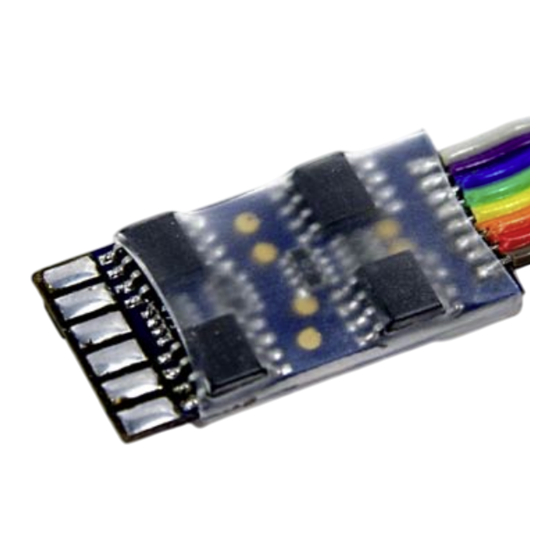
Ein Kurzschluss zwischen den einzelnen Leitungen kann den Decoder beschädi- gen und im schlimmsten Fall zerstören. Abbildung 2: eMOTION 8FL Decoder Anschlußbelegung (Ansicht Kabelseite) Illustration #2: eMOTION 8FL decoder pin assignment (Cable side view) 2.4 Connecting the function outputs 2.4. Anschluss der Funktionsaus- gänge 2.4.1. -
Seite 11: Spannungspuffer
CV-Tabelle im Anhang dieser Einbau- und Betriebsanleitung. und Betriebsanleitung. 2.5. Spannungspuffer 2.5. Spannungspuffer An Dec+ und Dec- können Massoth- An Dec+ und Dec- können Massoth- PowerCaps oder einfache Spannungs- PowerCaps oder einfache Spannungs- puffer (mit Ladeschaltung) angeschlos- puffer (mit Ladeschaltung) angeschlos- sen werden. -
Seite 12: Inbetriebnahme
3.1 Basic factory default settings Die Grundeinstellungen des eMOTION The basic factory default settings of the 8FL Decoders sind in der folgenden eMOTION 8FL decoder are shown in the Tabelle dargestellt. following table. Grundeinstellung des Funktionsdecoders Basic settings Function decoder... -
Seite 13: Zur Programmierung
Last angeschlossen sein ! 4.1. Lokadresse 4.1 Locomotive address Wird der eMOTION 8FL Decoder in In case the eMOTION 8FL decoder is Verbindung mit anderen Decodern used in connection with other decoders, verwendet, muss die Programmierung the address must be programmed in der Adresse vorab erfolgen. - Seite 14 all-gui des.c...
-
Seite 15: Programmiersperre Cv
All manuals and user guides at all-guides.com 4.2. Programmiersperre CV 15 / 16 4.2 Programming Lock CV 15 / 16 Um ein versehentliches Programmieren To prevent unintentional programming zu verhindern ist in CV 15 und 16 eine this decoder offers a programming lock Programmiersperre realisiert. -
Seite 16: Programmieradresse Cv 107/108
All manuals and user guides at all-guides.com 4.3. Programmieradresse CV 107 / 4.3 Programming Address 108 (nur POM) CV 107 / 108 (POM only) Diese Adresse wird benötigt um den The programming address is used to Decoder später im eingebauten Zustand programm the decoder after installation (mit weiteren Decodern) programmieren (when other decoders are installed). - Seite 17 All manuals and user guides at all-guides.com Funktionen: Functions: • Paarweise Wechselfunktion • pairwise alternating function Wechselblinker, in Abhängigkeit in dependence of previous function mit vorhergehendem Ausgang output (e.g. A2 to A1, A4 to A3, etc.) (z.B. A2 zu A1, A4 zu A3, etc.) • Zeitfunktion, symetrisch • flash function, symetric symetrisches Blinken...
- Seite 18 All manuals and user guides at all-guides.com Invertierung: Inversion: • Inverser Ausgang • Output inversion Funktion wird invertiert wenn aktiv If activated, function is inverted (nur bei Servobetrieb möglich) (only for servo operation) Dimmwert (PWM): Dimming (PWM): Alle Funktionsausgänge können pro- All function outputs can be dimmed zentual (2%...
-
Seite 19: Servofunktion
Servobereich frei positioniert werden. Beachten sie die CV-Liste zur Einstel- Beachten sie die CV-Liste zur Einstel- lung der Servofunktion. lung der Servofunktion. Servo Abbildung 3: Servoansteuerung mit dem eMOTION 8FL und 6V Regler Illustration #3: Servo control with eMOTION 8FL and 6V Regulator... - Seite 20 all-gui des.c...
-
Seite 21: Analogbetrieb
All manuals and user guides at all-guides.com 5.2. Massoth-Entkuppler 5.2. Massoth-Entkuppler Der Entkuppler kann an jedem der 8 Der Entkuppler kann an jedem der 8 Ausgänge betrieben werden. Verbinden Ausgänge betrieben werden. Verbinden sie das rote Kabel mit „Dec+“ , das sie das rote Kabel mit „Dec+“... - Seite 22 All manuals and user guides at all-guides.com...
- Seite 23 All manuals and user guides at all-guides.com...
-
Seite 24: Merkmale Der Funktionsausgänge
All manuals and user guides at all-guides.com Merkmale der Funktionsausgänge Funktion An/Aus Deaktiviert Dauer-An Paarw. Wechself. nur vorwärts nur rückwärts nur Stand nur Fahrt Zeitfunktion sym. Zeitfunktion asym. kurz Zeitfunktion asym. lang Monoflop Einschaltverzögerung Kesselfeuer TV flackern Fotograf/Blitzlicht Petroleum flackern Leuchtstoffröhre Start Marslight Single Strobe Double Strobe... - Seite 25 All manuals and user guides at all-guides.com Features of the Function Outputs Function On/Off Deactivated Permanent-ON pairwise alternating forwards only backwards only standing only moving only timer symetric flash timer asym. flash short timer asym. flash long Monoflop Switch-ON delay Firebox TV flickering Photographer flash Petroleum flickering Flourescent tube Marslight Single strobe Double Strobe servo function precision servo function...
- Seite 26 all-gui des.c...
- Seite 27 All manuals and user guides at all-guides.com CV - Tabelle Standardeinstellungen des 8FS-Decoders. (S = Standard, A = Analogbetrieb) Konfigurationsvariablen (CV-Tabelle) CV Beschreibung A Bereich Bemerkung Lokadresse (standard kurz) 1...127 wenn CV 29, Bit 5 = 0 Software Versionsnummer nur lesbar Herstellerkennung nur lesbar Decoder-Resetfunktion...
- Seite 29 All manuals and user guides at all-guides.com Konfigurationsvariablen (CV-Tabelle) CV Beschreibung A Bereich Bemerkung 116 A1: Zeitwert für Sonderfunktion 10 √ 1...250 Zeitbasis 0,1s pro Wert 120 A2: Schaltbefehlszuordnung A siehe Anhang 2 122 A2: Dimmwert (kein Servo) 100 √ siehe Anhang 3 123 A2: Bedingungen √...
- Seite 31 All manuals and user guides at all-guides.com Konfigurationsvariablen (CV-Tabelle) CV Beschreibung A Bereich Bemerkung 175 A7: Sonderfunktion √ siehe Anhang 5 176 A7: Zeitwert für Sonderfunktion 10 √ 1...250 Zeitbasis 0,1s pro Wert 180 A8: Schaltbefehlszuordnung A siehe Anhang 2 182 A8: Dimmwert / Servofunktion 100 √...
- Seite 32 all-gui des.c...
-
Seite 34: Anhang 1: Cv 29 - Nmra Konfiguration
All manuals and user guides at all-guides.com Anhang 1: CV 29 - NMRA Konfiguration Bit Wert AUS (Wert=0) Bemerkung normale Fahrtrichtung inverse Fahrtrichtung 128 Fahrstufen werden 14 Fahrstufen 28 Fahrstufen automatisch erkannt nur Digitalbetrieb Digital + Analogbetrieb kurze Lokadresse lange Lokadresse (gespeichert in CV 1) (gespeichert in CV 17 + 18) Anhang 1 Erklärung und Beispiel: Grundlegende Werte für CV 29 Wert Funktion... -
Seite 36: Anhang 3: Cv 112, 122, 132, 142, 172, 182 - Dimmwerte + Servofunktion
All manuals and user guides at all-guides.com Anhang 3: CV 112, 122, 132, 142, 172, 182 – Dimmwerte + Servofunktion Wert Verwendung Bemerkung 1-100 Prozentuale Spannung am Ausgang (100% = keine Dimmung) Servofunktion Standard Servofunktion Standard mit Endabschaltung Präzisionsservo (hohe Stufenauflösung) Servo (standard) mit Fahrstufen Servo (standard) mit Fahrstufen + Endabschaltung Inv. - Seite 38 all-gui des.c...
-
Seite 39: Anhang 5: Cv 115, 125, 135, 145, 155, 165, 175, 185 - Sonderfunktionen
All manuals and user guides at all-guides.com Anhang 4: CV 113, 123, 133, 143, 153, 163, 173, 183 – Bedingungen Wert Verwendung Bemerkung Nur im Stand „Vorwärts“ Nur im Stand „Rückwärts“ Nur bei Fahrt Nur bei Fahrt „Vorwärts“ Nur bei Fahrt „Rückwärts“ Anhang 5: CV 115, 125, 135, 145, 155, 165, 175, 185 –... -
Seite 43: Technische Daten
Kondenswasserbildung zu sufficient to prevent condensed water. verhindern. 6.1 Warranty, Service, Support 6.1. Garantie, Reparatur, Kunden- MASSOTH warrants this product against defects in materials and workmanship dienst for one year from the original date of MASSOTH gewährt die Fehlerfreiheit purchase. Other countries might have dieses Produkts für ein Jahr. - Seite 44 all-gui des.c...
-
Seite 45: Hotline
Kaufbelegs wird vorausgesetzt. Return shipping charges are not cove- Für Schäden durch unsachgemäße red by MASSOTH. Please include your Behandlung oder Fremdeingriff oder proof of purchase with the returned Veränderung des Produkts besteht kein goods. - Seite 47 All manuals and user guides at all-guides.com Dieses Produkt entspricht den CE Konformitätsrichtlinien für elektrische Kleingeräte in der aktuellen Fassung. This unit conforms to the CE Standards Dieses Produkt ist nach den aktuellen EG Richtlinien umgangssprachlich „bleifrei“ hergestellt und damit RoHS-konform. RoHS This unit is manufactured according to the latest EG Standards COMPLIANT...