Herunterladen Inhalt Inhalt Diese Seite drucken
PeakTech 3441 Bedienungsanleitung

PeakTech 3441 Bedienungsanleitung

Digital-multimeter
Vorschau ausblenden Andere Handbücher für 3441:

Werbung

Verfügbare Sprachen

Verfügbare Sprachen

PeakTech
®
3441
Manual de uso
Multímetro digital

Werbung

Inhaltsverzeichnis
loading

Inhaltszusammenfassung für PeakTech 3441

  • Seite 1 PeakTech ® 3441 Manual de uso Multímetro digital...
  • Seite 2: Precauciones De Seguridad

    1. Precauciones de seguridad Este producto cumple con los requisitos de las siguientes Directivas Comunidad Europea: 2004/108/CE (Compatibilidad electromagnética) y 2006/95/CE (Bajo voltaje) enmendada por 2004/22/CE (Marcado CE). Sobretensión de categoría III 1000 V. Sobretensión de categoría IV 600 V. Contaminación de grado 2. CAT I: Para nivel de señal, telecomunicaciones, electrónica con pequeñas sobretensiones transitorias.
  • Seite 3  El medidor está diseñado para soportar la tensión máxima establecida, que se excederá si no es posible evitar impulsos, transitorios, perturbaciones o por otras razones. Se debe usar una preescala adecuada (10:1).  Sustituya el fusible defectuoso solamente por un fusible del mismo valor del original.
  • Seite 4  Mantenga lejos del equipo electrodos o soldadores calientes.  Permita que el equipo se estabilice a temperatura ambiente antes de tomar las mediciones (importante para mediciones exactas).  Mantenga lejos del equipo electrodos o soldadores calientes.  No introduzca valores por encima del rango máximo de cada medición para evitar daños al medidor.
  • Seite 5 1.1 Introducción El nuevo PeakTech 3441 es un práctico multímetro para grandes cargas con muchas funciones útiles de medición. La pantalla de medición del dispositivo se puede cambiar de 3 5/6 dígitos a 4 5/6 dígitos de alta resolución...
  • Seite 6 1.3 Símbolos de seguridad TÜV/GS aprobado; TÜV-Rheinland ¡Atención! Lea la sección correspondiente en el manual. El incumplimiento supone riesgo de lesiones y / o riesgo de daños en el dispositivo. La diferencia máx. de tensión permitida de 1000 V CC/CArms entre COM / V o entrada de ohmio y tierra no se excede por razones de seguridad.
  • Seite 7: Descripción Del Panel Frontal

    2. Descripción del panel frontal...
  • Seite 8 1. Pantalla TFT/LCD con recuento máximo de 60.000. 2. Tecla RANGE: para cambiar entre rangos de medida de forma manual. 3. Tecla HIRES/Retroiluminación: para seleccionar la resolución de la pantalla y cambiar la luz de fondo. 4. Tecla MODE: para cambiar entre funciones de medición. 5.
  • Seite 9: Manual De Uso

    3. Manual de uso ¡Advertencia! ¡Riesgo de electrocución! Circuitos de alta tensión, tanto CA como CC son muy peligrosos y se deben medir con extremo cuidado. Tenga siempre el selector en la posición OFF cuando no esté usando el medidor. Este medidor tiene apagado automático, que apaga el equipo de forma automática a los 30 minutos de su último uso.
  • Seite 10 3.2 Selección de rango automático / manual Cuando se enciende el medidor por primera vez, está por defecto en rango automático. Esto selecciona de forma automática el mejor rango para las mediciones que se realicen y es generalmente el mejor modo para la mayoría de las mediciones. Para mediciones que requieran que se seleccione el rango manualmente, siga los siguientes pasos: 1.
  • Seite 11 Hz / REL: Pulsando la tecla Hz% / ΔREL cambia a rango de medición de tensión CA o rango de frecuencia y muestra el ciclo de trabajo. Mantenga pulsada la tecla REL durante 1 segundo y la función de valor relativo se activa, reseteándose el medidor a “cero”.
  • Seite 12 Descripción de la pantalla Probador de continuidad Probador de diodo Estado de batería Nano (10 Micro (10 Mili (10 Amperio (Corriente) Kilo Faradio (Capacitancia) Mega (10 Ohmio (Resistencia) Detección de pico Hercio (Frecuencia) Voltio (Tensión) Ciclo de trabajo Función relativa Corriente alterna Rango automático Corriente continua...
  • Seite 13 4.3 Descripción del selector Seleccione una función de medición inicial colocando el selector en uno de los iconos que rodean el perímetro. Para cada función, el medidor presenta una pantalla estándar para esa función (rango, unidades de medición, y modificadores). La elección realizada en una función no se traslada a otra función.
  • Seite 14 4.4 Uso de los terminales de entrada Todas las funciones excepto las de medición de corriente usan los terminales de entrada V//CAP/Hz%/Temp y COM. Entrada para corriente de 0 A a 10.00 A (20VA sobrecarga durante 30 segundos encendido, 10 minutos apagado). Entrada para mediciones de corriente de 0 A µA mA a 600 mA.
  • Seite 15 5. Funcionamiento 5.1 Mediciones de tensión CC 1. Coloque el selector en la posición verde. 2. Inserte la sonda de test negra en el conector negativo COM. Inserte la sonda de test roja al conector positivo V//CAP/Hz%/ Temp. Lea la tensión en la pantalla. Cuando el valor sea negativo, se mostrará...
  • Seite 16 5.2 Medición de tensión (mV) ¡Precaución! No mida tensiones CC si un motor del circuito está arrancando o parando. Durante las operaciones de arranque o parada, se pueden dar grandes aumentos de tensión que pueden dañar el medidor. ¡Precaución! Interpretación de lecturas fantasma: En algunos rangos de tensión CC y CA, cuando las sondas de test no están conectadas a ningún circuito, la pantalla podría mostrar una lectura fantasma.
  • Seite 17 1. Coloque el selector en la posición mV 2. Pulse la tecla MODE para seleccionar mV (CC) o mV~ (CA). 3. Inserte la sonda de test negra en el conector negativo COM. Inserte la sonda de test roja al conector positivo V//CAP/Hz%/ Temp.
  • Seite 18 1. Coloque el selector en la posición "V~". 2. Pulse la tecla “F2” para seleccionar CA “~”. Inserte la sonda de test negra en el conector negativo COM y sonda de test roja al conector positivo V//CAP/Hz%/Temp. 4. Toque con las puntas de la sonda de prueba el circuito bajo prueba.
  • Seite 19 5.4 Mediciones de % frecuencia / ciclo de trabajo 1. Coloque el selector en la posición "Hz%". 2. Use la tecla MODE para cambiar entre frecuencia (Hz) y ciclo de trabajo (%). Inserte la sonda de test negra en el conector negativo COM y sonda de test roja al conector positivo V//CAP/Hz%/Temp.
  • Seite 20 5.5 Mediciones de resistencia Advertencia: Para evitar descargas eléctricas, desconecte la alimentación de la unidad bajo prueba y descargue todos los condensadores antes de tomar cualquier medición de resistencia. Quite la batería y desconecte los cables de alimentación. -19-...
  • Seite 21 en la posición " Ω / 1. Coloque el selector " Inserte la sonda de test negra en el conector negativo y la sonda de test roja al conector positivo V//CAP/Hz%/Temp. 3. Toque con las puntas de las sondas de prueba el circuito o la parte bajo prueba.
  • Seite 22 en la posición " Ω/ 1. Coloque el selector /CAP ". 2. Pulse la tecla MODE para seleccionar la prueba de continuidad. Inserte la sonda de test negra en el conector negativo y la sonda de test roja al conector positivo V//CAP/Hz%/Temp.
  • Seite 23 5.7 Prueba de diodo La prueba de diodo permite determinar la usabilidad de los diodos y otros elementos semiconductores establecidos en circuitos, además de determinar la continuidad (cortocircuito) y la caída de tensión directa. Advertencia: Para evitar descargas eléctricas, no pruebe ningún diodo que contenga tensión.
  • Seite 24 1. Coloque el selector en la posición "Ω/ /CAP". 2. Pulse la tecla MODE hasta que aparezca el símbolo " " en la pantalla. Inserte la sonda de test negra en el conector negativo COM y el conector de la sonda de test roja al conector positivo V//CAP/Hz%/Temp.
  • Seite 25 5.8 Mediciones de capacitancia Advertencia: Para evitar descargas eléctricas, desconecte la alimentación de la unidad bajo prueba y descargue todos los condensadores antes de tomar medición de capacitancia. Quite las pilas y desconecte los cables de alimentación. en la posición “Ω/ /CAP“.
  • Seite 26 5.9 Mediciones de temperatura Advertencia: • Para evitar descargas eléctricas, desconecte las sondas de test de cualquier fuente de tensión antes de tomar cualquier medición de temperatura. • Para evitar descargas eléctricas, asegúrese de que el termopar se haya quitado antes de cambiar a cualquier otra función de medición. en la posición “TEMP °C/°F”.
  • Seite 27 Lea la temperatura en la pantalla. La lectura digital indicará el punto decimal adecuado y el valor. 5.10 Mediciones de corriente CC Advertencia: Para evitar descargas eléctricas, no mida corriente CC en ningún circuito cuya tensión supere los 1000V CC/CA Precaución: No haga mediciones de corriente en la escala 10A durante más de 30 segundos.
  • Seite 28 1. De acuerdo con la corriente que se vaya a medir, gire el selector a la posición de uA, mA o 10A. 2. Coloque el dispositivo en la función de medición CC (DC " ") pulsando la tecla MODE. En la pantalla aparecerá el icono de funcionamiento (DC “...
  • Seite 29 5.11 Mediciones de corriente CA Advertencia: Para evitar descargas eléctricas, no mida corriente CA en ningún circuito cuya tensión supere los 1000V CC/CA Precaución: No haga mediciones de corriente en la escala 10A durante más de 30 segundos. Superar los 30 segundos puede causar daños al medidor y / o las sondas de test.
  • Seite 30 ¡Atención! Las mediciones de corriente de rango 10A y uA / mA están protegidos por fusibles contra sobrecorriente. Los fusibles fundidos se deben sustituir por otros nuevos del mismo tipo antes de iniciar otras mediciones. No es posible realizar mediciones de corriente con fusibles fundidos.
  • Seite 31 5.12 Mediciones 4 – 20mA % Los circuitos de 4 - 20 mA representan una transmisión eléctrica analógica estándar para los instrumentos industriales y la comunicación. En tales circuitos, 4 mA corresponden al 0% de la señal y 20 mA al 100%. La posición cero en 4 mA permite que el instrumento receptor distinga entre una señal cero y un cable roto o un equipo defectuoso.
  • Seite 32 Sustitución de la batería Consulte la ilustración y sustituya la batería de la forma siguiente: 1.) Apague el medidor y quite las sondas de test de los terminales. 2.) Abra la tapa de la batería usando un destornillador para girar el tornillo media vuelta en sentido antihorario.
  • Seite 33 6.1 Notificación sobre Regulaciones de Baterías El suministro de muchos dispositivos incluye pilas que sirven, por ejemplo, para manejar el mando a distancia. Podría haber baterías o acumuladores integrados en el dispositivo. En relación con la venta de estas baterías o acumuladores, estamos obligados de acuerdo con las Regulaciones sobre Baterías a notificar a nuestros clientes lo siguiente: Deposite las pilas usadas en un punto establecido para ello o...
  • Seite 34: Sustitución De Los Fusibles

    7. Sustitución de los fusibles Advertencia: Para evitar descargas eléctricas, desconecte las sondas de test de cualquier fuente de tensión antes de quitar la cubierta trasera o la puerta de la batería/pila. 1. Gire el tornillo del compartimento de la batería media vuelta en sentido antihorario para abrirlo.
  • Seite 35: Datos Técnicos

    8. Datos técnicos 8.1 Especificaciones Pantalla Pantalla TFT-LCD con un recuento máximo de 59999. Protección sobrecarga En todos los rangos. Temp. de funcionamiento 5°C a 40°C < 80 % HR Temp. de almacenamiento -20...+60° C < 80 % HR Altitud <...
  • Seite 36 El término viene de “Root-Mean- True RMS CA o corriente Square”, que representa el método de cálculo del valor de tensión. Normalmente los multímetros se calibran para leer correctamente solo las ondas sinusoidales y leen manera imprecisa sinusoidales o distorsionadas. Los medidores con True RMS leen con precisión cualquier tipo de señal.
  • Seite 37 8.3 Especificaciones (HiRes) Tensión CA 50 Hz – 1kHz Rango Resolución 1kHz - 5kHz 600 mV 0,01 mV 0,0001V ± 3,0% + 5 dgt. 60 V 0,001V ± 1%+ 5 St. 600 V 0,01V 1000 V 0,1V No especificada Precisión >10% de rango Tensión CC Rango Resolución...
  • Seite 38 Rango Resolución Precisión 600   ± 2% + 9 dgt. 0,01 6 k 0,0001k 60 k 0,001 k Resistencia () ± 1,2% + 5 dgt. 600 k 0,01 k 6 M 0,0001 M ± 2,0% + 10 dgt. 60 M 0,001 M...
  • Seite 39 Frecuencia (Cuadrado) 60 Hz 0,001 600 Hz 0,01 6 kHz 0,0001 kHz ± 1.0% + 2 dgt. 60 kHz 0,001 600 kHz 0,01 10 MHz 0,001 MHz No especificada Sensibilidad: 2V rms min.@20% a 80% ciclo de trabajo y <100kHz 5Vrms min@20% a 80% ciclo de trabajo y >...
  • Seite 40 Recomendamos calibrar la unidad de nuevo pasado 1 año. ® © PeakTech 03/2017/MP PeakTech Prüf- und Messtechnik GmbH – Gerstenstieg 4 – DE-22926 Ahrensburg / Germany +49-(0) 4102-42343/44 +49-(0) 4102-434 16   info@peaktech.de...
  • Seite 41: Digital-Multimeter

    3441 / 3442 ® PeakTech Bedienungsanleitung / 3442 Operation Manual Digital-Multimeter...
  • Seite 42: Eu-Konformitätserklärung

    EU - Konformitätserklärung PeakTech 3442 Hiermit erklärt PeakTech Prüf- und Messtechnik GmbH, dass der Funkanlagentyp [P 3442 - Multimeter mit Bluetooth-Schnittstelle] der Richtlinie 2014/53/EU, elektromagnetische Kompatibilität der Richtlinie 2014/30/EU und Gerätesicherheit der Niederspannungsrichtlinie 2014/35/EU entspricht. Der vollständige Text der EU-Konformitätserklärung ist unter der folgenden Internetadresse verfügbar:...
  • Seite 43: Sicherheitshinweise

    1. Sicherheitshinweise Dieses Produkt erfüllt die Anforderungen der folgenden Richtlinien Europäischen Union CE-Konformität: 2014/30/EU (Elektromagnetische Verträglichkeit), 2014/35/EU (Niederspannung), 2011/65/EU (RoHS). Überspannungskategorie III 1000V; Überspannungskategorie IV 600V; Verschmutzungsgrad 2. CAT I: Signalebene, Telekommunikation, elektronische Geräte mit geringen transienten Überspannungen CAT II: Für Hausgeräte, Netzsteckdosen, portable Instrumente etc.
  • Seite 44  Gerät nicht in der Nähe starker magnetischer Felder (Motoren, Transformatoren usw.) betreiben  maximal zulässige Eingangsspannung von 1000V DC/AC nicht überschreiten.  maximal zulässige Eingangswerte unter keinen Umständen überschreiten (schwere Verletzungsgefahr und/oder Zerstörung des Gerätes)  Die angegebenen maximalen Eingangsspannungen dürfen nicht überschritten werden.
  • Seite 45  Messarbeiten nur in trockener Kleidung und vorzugsweise in Gummischuhen bzw. auf einer Isoliermatte durchführen.  Messspitzen der Prüfleitungen nicht berühren.  Warnhinweise am Gerät unbedingt beachten.  Gerät darf nicht unbeaufsichtigt betrieben werden  Bei unbekannten Messgrößen vor der Messung auf den höchsten Messbereich umschalten.
  • Seite 46  Dieses Gerät ist ausschließlich für Innenanwendungen geeignet.  Vermeiden Sie jegliche Nähe zu explosiven und entflammbaren Stoffen.  Öffnen des Gerätes und Wartungs – und Reparatur-arbeiten dürfen nur von qualifizierten Service-Technikern durchgeführt werden.  Gerät nicht mit der Vorderseite auf die Werkbank oder Arbeitsfläche legen, um Beschädigung der Bedienelemente zu vermeiden.
  • Seite 47 1.1 Einleitung Das neue PeakTech 3441 ist ein praktisches Digital-Multimeter für hohe Beanspruchung mit einer Vielzahl an nützlichen Messfunktionen. Die Messanzeige des Gerätes lässt sich auf Tastendruck zwischen 3 5/6- stelliger LCD auf eine hochauflösende 4 5/6-stellige LCD umschalten, wobei alle Messungen als Echt-Effektivwert erfasst werden.
  • Seite 48 1.3. Sicherheitssymbole und Hinweise am Gerät Gerät ist TÜV/GS geprüft; TÜV-Rheinland Achtung! Entsprechende(n) Abschnitt(e) in der Bedienungsanleitung nachlesen. Nichtbeachtung birgt Verletzungsgefahr und/oder die Gefahr der Beschädigung des Gerätes. max. zulässige Spannungsdifferenz von 1000 V DC/AC zwischen COM-/ V-/ bzw. Ohm-Eingang und Erde aus Sicherheitsgründen nicht überschreiten.
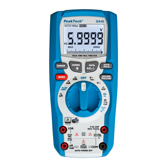
  • Seite 49: Bedienelemente Und Anschlüsse Am Gerät

    2. Bedienelemente und Anschlüsse am Gerät...
  • Seite 50 1. TFT/LCD-Display mit einer Anzeige von max. 60.000 2. RANGE-Taste: Umschaltung auf manuelle Bereichswahl 3. HIRES / Backlight-Taste: Zum Umschalten der Anzeige- auflösung und Einschalten der Hintergrundbeleuchtung. 4. MODE-Taste: Umschalten der Messfuktionen. Gerdrückt halten zum aktivieren der Bluetooth Schnittstelle (nur P3442) 6.
  • Seite 51: Hinweise Zur Inbetriebnahme Des Gerätes

    3. Hinweise zur Inbetriebnahme des Gerätes Achtung! Messungen an Schaltungen mit hohen Spannungen (AC und DC) mit äußerster Vorsicht und nur in Übereinstimmung mit den relevanten Sicherheitsbestimmungen vornehmen. Gerät nach Beendigung des Messbetriebes stets ausschalten. Das Messgerät verfügt über eine interne Abschaltautomatik die das Gerät automatisch max.
  • Seite 52 3.2. Umschaltung von automatischer auf manuelle Bereichswahl Beim Einschalten des Gerätes wird immer die automatische Bereichswahl aktiviert. Die automatische Bereichswahl erleichtert den Messbetrieb und garantiert optimale Messergebnisse. Zur Umschaltung auf manuelle Bereichswahl wie beschrieben verfahren: 1. Taste RANGE drücken. Beim Drücken der Taste erlischt die Anzeige AUTO und der zuletzt gewählte Bereich bleibt weiterhin aktiviert.
  • Seite 53 Hz/REL Durch Betätigen der Hz%/∆REL-Taste wird im Wechsel- spannungmessbereich oder Frequenzmessbereich zwischen der Spannungsmessung, Frequenzmessung und der Anzeige des Tastverhältnis umgeschaltet. Halten Sie die REL-Taste für ca. 1 sek. Gedrückt, schaltet sich die Relativwertfunktion ein und die Messanzeige wird auf „Null“...
  • Seite 54 4.2. Beschreibung der Anzeige Durchgangsprüfung Diodenprüfung Batterie Status Nano (10 Mikro (10 Milli (10 Ampere (Strom) Kilo Farad (Kapazität) Mega (10 Ohm (Widerstand) Spitzenwerterfassung Hertz (Frequenz) Volt (Spannung) Tastverhältnis Relativwertfunktion Wechselspannung Automatische Bereichswahl Gleichspannung Messwerthaltefunktion Fahrenheit Celsius Maximalwertfunktion Minimalwertfunktion...
  • Seite 55 4.3. Funktionsweise des Drehwahlschalters Wählen Sie eine primäre Messfunktion, indem Sie den Drehschalter auf eine der möglichen Funktionen drehen. Das Messgerät stellt für jede einzelne Messfunktion eine Standardanzeige (Messbereich, Maßeinheiten und Modifikatoren). Ausgewählte Tastenoptionen werden nicht auf andere Messfunktionen übertragen. Spannungsmessfunktion AC V–...
  • Seite 56 4.4. Verwenden der Eingangsbuchsen Für alle Funktionen, außer der Strommessfunktion werden die V//CAP/Hz%/Temp und COM-Eingangsanschlüsse verwendet. Eingang für 0 A bis 10,00 A Strom (20 VA Überlast für 30 Sekunden ein, 10 Minuten aus) µA mA Eingang für Strommessungen bis 600mA Masse-Anschluss für alle Messungen Eingang für Spannung, Kontinuität, V / Ω...
  • Seite 57 5. Messbetrieb 5.1.Gleichspannungsmessung (V DC) 1. Funktionswahlschalter in Stellung V 2. Rote Prüfleitung an den V//CAP/Hz%/Temp-Eingang und die schwarze Prüfleitung an den COM-Eingang des Gerätes anschließen. 3. Prüfleitungen über die zu messendende Spannungsquelle anlegen und Messwert in der LCD-Anzeige des Gerätes ablesen.
  • Seite 58 5.2. Spannungsmessung (mV) Achtung! Vor dem Ein- bzw. Ausschalten der Messschaltung Prüfleitungen von der Messschaltung abziehen. Hohe Einschaltströme oder - spannungen könnten sonst u.U. das Messgerät beschädigen bzw. zerstören. Achtung! Phantomwerte niedrigen Spannungsbereichen nicht angeschlossenen und somit offenen Eingängen zeigt die LCD- Anzeige sogenannte Phantomwerte, d.
  • Seite 59 1. Funktionswahlschalter in Stellung mV 2. Mit der Taste MODE die mV - oder mV~ Funktion auswählen. 3. Rote Prüfleitung an den V//CAP/Hz%/Temp-Eingang und die schwarze Prüfleitung an den COM-Eingang des Gerätes anschließen. Prüfleitungen über die zu messendende Spannungsquelle anlegen und Messwert in der LCD-Anzeige des Gerätes ablesen.
  • Seite 60 Zur Messung von Wechselspannungen wie beschrieben verfahren: 1. Funktionswahlschalter in Stellung "V~" drehen. 3. Rote Prüfleitung an den V//CAP/Hz%/Temp-Eingang und schwarze Prüfleitung an den -Eingang des Gerätes anschließen. 4. Prüfleitungen über die zu messende Spannungsquelle anlegen und Messwert in der LCD-Anzeige des Gerätes ablesen. 5.
  • Seite 61 5.4 Frequenzmessung/ Tastverhältnis Zur Messung wie beschrieben verfahren: 1. Funktionswahlschalter in Stellung „Hz%“ drehen. 2. Mit der MODE Taste zwischen Frequenz (Hz) und Duty Cycle (%) umschalten. 3. Rote Prüfleitung an den V//CAP/Hz%/Temp -Eingang und schwarze Prüfleitung an den COM - Eingang des Gerätes anschließen.
  • Seite 62 5.5. Widerstandsmessung Achtung! Nach Umschaltung Multimeters Widerstandsmessfunktion angeschlossene Prüfleitungen nicht an eine Spannungsquelle anlegen. Widerstandsmessungen nur an spannungsfreien Schaltungen bzw. Bauteilen vornehmen und Netzstecker aus der Steckdose ziehen. In der Schaltung befindliche Kondensatoren vor der Messung unbedingt entladen.
  • Seite 63 Zur Messung wie beschrieben verfahren: 1. Funktionswahlschalter in Stellung "Ω / / CAP" drehen. 2. Rote Prüfleitung an den V//CAP/Hz%/Temp -Eingang und Schwarze Prüfleitung an den COM – Eingang anschließen. 3. Prüfleitungen über den zu messenden Widerstand anlegen. 4. Messwert in der LCD-Anzeige ablesen. Hinweis: Der Eigenwiderstand der Prüfleitungen kann bei Messungen von kleinen Widerständen (600 Ohm-Bereich) die Genauigkeit der...
  • Seite 64 Zur Messung wie beschrieben verfahren: 1. Funktionswahlschalter in Stellung "Ω/ /CAP" drehen. 2. Taste MODE drücken, Durchgangsprüffunktion auszuwählen. 3. Rote Prüfleitung an den V//CAP/Hz%/Temp -Eingang und schwarze Prüfleitung an den COM - Eingang des Gerätes anschließen. 4. Wenn der Widerstand unter ca. 30Ω liegt, ertönt das akustische Signal.
  • Seite 65 5.7. Diodenprüffunktion Diodentestfunktion ermöglicht Bestimmung Verwendbarkeit von Dioden und anderen Halbleiter-Elementen in definierten Schaltungen, sowie die Bestimmung der Durchgängigkeit (Kurzschluss) und des Spannungsabfalls in Durchlassrichtung. Achtung! Vor Überprüfung der Diode, Bauteil bzw. Schaltung unbedingt spannungslos schalten oder Diode aus der Schaltung auslöten.
  • Seite 66 Zur Durchführung des Diodentests wie beschrieben verfahren: 1. Funktionswahlschalter in Stellung Ω/ /CAP drehen. 2. Gerät auf die Diodentestfunktion durch Drücken der Taste MODE umschalten. In der LCD-Anzeige leuchtet das Symbol " " auf. 3. Rote Prüfleitung an den V//CAP/Hz%/Temp -Eingang und schwarze Prüfleitung an den COM-Eingang des Gerätes anschließen.
  • Seite 67 5.8. Kapazitätsmessung Achtung! Kapazitätsmessungen spannungslosen Schaltungen durchführen und Kondensator vor der Messung unbedingt entladen. Kondensator zur Messung aus der Schaltung auslöten. Messung wie beschrieben durchführen: 1. Funktionswahlschalter in Stellung "Ω/ /CAP" drehen. 2. Taste MODE drücken, Kapazitätsmessfunktion auszuwählen. 3. Rote Prüfleitung an den V//CAP/Hz%/Temp-Eingang und schwarze Prüfleitung an den COM-Eingang des Gerätes anschließen.
  • Seite 68 4. Prüfleitungen über den zu messenden Kondensator anlegen (Polarität beachten!). 5. Messwert in der LCD-Anzeige ablesen. 5.9. Temperaturmessfunktion Achtung! Temperaturmessungen nur an spannungsfreien Schaltungen bzw. Messobjekten vornehmen.
  • Seite 69 Temperaturmessung wie beschrieben durchführen: 1. Funktionswahlschalter in Stellung "TEMP °C/°F" drehen. 2. Taste MODE betätigen, um °C oder °F auszuwählen. 3. Adapter für Temperaturmessungen Eingangsbuchsen V//CAP/Hz%/Temp (+) und COM (-) einstecken. 4. Typ-K Temperaturfühler Temperaturadapter anschließen (auf korrekte Polarität achten!). 5.
  • Seite 70 1. Entsprechend der zu messenden Stromgröße Funktionswahlschalter entweder in Stellung µA, mA oder 10A drehen. 2. Gerät auf die Gleichstrommessfunktion (DC „ “) durch Drücken der Taste MODE umschalten. In der LCD-Anzeige leuchtet das Funktionssymbol DC auf. 3. Abhängig von der zu messenden Stromstärke rote Prüfleitung an den µA/mA - oder den 10A - Eingang und schwarze Prüfleitung an den COM - Eingang des Gerätes anschließen.
  • Seite 71 4. Zu messende Schaltung spannungslos schalten und am gewünschten Messpunkt "öffnen". Prüfleitungen in Reihe anschließen (auf korrekte Polarität achten!). 5. Spannung an die Messschaltung anlegen und Messwert in der LCD-Anzeige des Gerätes ablesen. Beim Messen negativer Gleichströme erscheint ein Minussymbol (-) links von der Messwertanzeige.
  • Seite 72 Achtung! Strommessungen µA/mA-Bereich sind durch Schmelzsicherungen gegen Überstrom abgesichert. Defekte Sicherungen müssen weiteren Messung gegen neue Sicherungen des gleichen Typs ausgewechselt werden. Bei ausgelösten Sicherungen ist keine Strommessung mehr möglich. Den maximalen Strommessbereich nicht überschreiten, um ein Auslösen der Sicherung zu vermeiden!
  • Seite 73 5.12. 4 – 20mA % Messung Stromkreise mit 4-20 mA stellen einen analogen elektrischen Übertragungsstandard für industrielle Messgeräte Kommunikation dar. In einem solchen Stromkreis entspricht ein Pegel von 4 mA 0 % und ein Pegel von 20 mA 100 % des Signals. Die Nullposition bei 4 mA erlaubt den empfangenden Messgeräten Unterscheidung zwischen...
  • Seite 74: Auswechseln Der Batterien

    6. Auswechseln der Batterien Ersetzen Sie die Batterien wie folgt: 1. Schalten Sie das Messgerät aus und entfernen Sie alle Messleitungen von den Eingangsbuchsen. 2. Drehen Sie die Schraube des Batteriefaches eine halbe Umdrehung gegen den Uhrzeigersinn, um das Batteriefach zu öffnen.
  • Seite 75 6.1. Hinweise zum Batteriegesetz Im Lieferumfang vieler Geräte befinden sich Batterien, die. z. B. zum Betrieb von Fernbedienungen dienen. Auch in den Geräten selbst können Batterien oder Akkus fest eingebaut sein. Zusammenhang mit dem Vertrieb dieser Batterien oder Akkus sind wir als Importeur gemäß...
  • Seite 76: Auswechseln Der Sicherungen

    7. Auswechseln der Sicherungen Achtung! Vor Abnahme des Batteriefachdeckels zum Auswechseln der Sicherungen, Prüfleitungen von den Eingängen des Multimeters abziehen und Gerät ausschalten. Defekte Sicherung nur durch eine dem Originalwert entsprechende Sicherung ersetzen. Zum Auswechseln der Sicherung wie beschrieben vorgehen: 1.
  • Seite 77: Technische Daten

    8. Technische Daten 8.1. Allgemeine Daten Anzeige LCD Anzeige mit einer maximalen Anzeige von 59999. Überlastschutz in allen Bereichen Betriebstemperaturbereich 5...40°C < 80 % RH Betriebshöhe < 2000 m max. Lagertemperaturbereich -20...+60°C < 80 % RH Temperaturbereich für 18...28°C angegebene Genauigkeit 8.2 Allgemeine technische Daten Gehäuse Doppelt isoliert, wasserdicht...
  • Seite 78 AC Echteffektiv Der Begriff steht für "Root-Mean- (True RMS) Square," repräsentiert die Berechnungsmethode der Spannungs- oder Stromwerte. Durchschnittliche Multimeter sind so kalibriert, um Sinuswellen korrekt anzuzeigen, jedoch zeigen diese Nicht-Sinussignale oder verzerrte Signale ungenau an. Geräte mit Echteffektiv-Funktion (True RMS) können auch diese Signaltypen genau anzeigen.
  • Seite 79 8.3. Spezifikationen (HiRes) Wechselspannung (ACV) 50 Hz – 1kHz Bereich Auflösung 1kHz - 5kHz 600 mV 0,01 mV 0,0001V ± 3,0% + 5 St. 60 V 0,001V ± 1%+ 5 St. 600 V 0,01V 1000 V 0,1V Nicht spezifiziert Genauigkeit bei >10% des Messbereiches Gleichspannung (DCV) Bereich Auflösung...
  • Seite 80 Bereich Auflösung Genauigkeit 600   ± 2% + 9 St. 0,01 6 k 0,0001k Widerstand 60 k 0,001 k ± 1,2% + 5 St. () 600 k 0,01 k 6 M 0,0001 M ± 2,0% + 10 St. 60 M 0,001 M...
  • Seite 81 Frequenz (Elektronisch) 60 Hz 0,001 600 Hz 0,01 ± 1,0% + 2 dgt. 6 kHz 0,0001 kHz 60 kHz 0,001 600 kHz 0,01 10 MHz 0,001 MHz Nicht spezifiziert Empfindlichkeit: 2,0V minimum bei 20% ~ 80% Tastverhältnis (duty cycle) und <100 kHz;...
  • Seite 82: Anhang 1: Aktivierung Der Bluetooth-Schnittstelle

    Betätigen Sie die Mode-Taste des P 3442 für ca. 2 Sekunden, um die Bluetooth-Schnittstelle zu aktiveren. Laden Sie die „PeakTech Meter App“ für Mobilgeräte oder die Windows-Software in Verbindung mit dem beliegenden USB- Bluetooth Adapter und such Sie nach dem passenden Modell in der Geräteauswahl.
  • Seite 83 Letzter Stand bei Drucklegung. Technische Änderungen des Gerätes, welche dem Fortschritt dienen, vorbehalten. Hiermit bestätigen wir, dass alle Geräte, die in unseren Unterlagen genannten Spezifikationen erfüllen und werkseitig kalibriert geliefert werden. Eine Wiederholung der Kalibrierung nach Ablauf von 1 Jahr wird empfohlen. ® © PeakTech...
  • Seite 84: Eu Declaration Of Conformity

    EU Declaration of Conformity Peak Tech 3442 Hereby PeakTech Prüf- und Messtechnik GmbH declares that the radio equipment type [P 3442 - Multimeter with Bluetooth interface] complies with the directive 2014/53 / EU, electromagnetic compatibility of Directive 2014/30 / EU and equipment safety of the Low Voltage Directive 2014/35 / EU.
  • Seite 85: Safety Precautions

    1. Safety Precautions This product complies with the requirements of the following directives of the European Union for CE conformity: 2014/30/EU (electromagnetic compatibility), 2014/35/EU (low voltage), 2011/65/EU (RoHS). Overvoltage category III 1000V; overvoltage category IV 600V; pollution degree 2. CAT I: For signal level, telecommunication, electronic with small transient over voltage CAT II:...
  • Seite 86  Replace a defective fuse only with a fuse of the original rating. Never short-circuit fuse or fuse holding.  Disconnect test leads or probe from the measuring circuit before switching modes or functions.  Do not conduct voltage measurements with the test leads connected to the µA/mA/A- and COM-terminal of the equipment.
  • Seite 87  Do not input values over the maximum range of each measurement to avoid damages of the meter.  Do not turn the rotary function switch during voltage or current measurement, otherwise the meter could be damaged.  Use caution when working with voltages above 35V DC or 25V AC.
  • Seite 88 1.1. Introduction The new PeakTech 3441 is a handy digital multimeter for heavy duty use with many useful measurement functions. The measurement display of the device can be switched from 3 5/6 digit to 4 5/6 digits high-resolution by keystroke, where all measurements are made as True RMS.
  • Seite 89 1.3. Safety Symbols TÜV/GS approved; TÜV-Rheinland Attention! Read the corresponding Section in the manual. Failure to comply entails risk of injury and / or the risk of damage to the device. max. allowable voltage difference of 1000 V DC/ACrms between COM / V or ohm input and earth does not exceed for safety reasons.
  • Seite 90: Front Panel Description

    2. Front Panel Description...
  • Seite 91 1. TFT / LCD display with an indication of max. 60.000 2. RANGE-Key: To switch measurement ranges manually 3. HIRES/ Backlight-Key: To select display resolution and switch backlight 4. MODE-Key: To switch the measurement functions. Hold key to activate Bluetooth interface (P3442 only) 5.
  • Seite 92 3. Operating instructions Warning! Risk of electrocution! High-voltage circuits, both AC and DC are very dangerous and should be measured with great care. Always push the power switch to the OFF position when the meter is not in use. This meter has Auto OFF that automatically shuts the meter OFF if max.
  • Seite 93 3.2. Autoranging / manual range selection When the meter is first turned on, it automatically goes into Auto- Ranging. This automatically selects the best range for the measurements being made and is generally the best mode for most measurements. For measurement situations requiring that the range be manually held, perform the following: 1.
  • Seite 94 Hz / REL: Pressing the Hz% / ΔREL-button switches in AC voltage measuring range or frequency range between the voltage measurement, frequency measurement and display of the duty cycle. Hold and keep pressed the REL button for about 1 sec. and the relative value function turns on, so the meter display will be reset to "zero".
  • Seite 95 4.2. Understanding the Display Continuity Tester Diode Tester Batterie Status Nano (10 Micro (10 Milli (10 Ampere (Current) Kilo Farad (Capacity) Mega (10 Ohm (Resistance) Peak detection Hertz (Frequency) Volt (Voltage) Duty Cycle Relative function Alternating Current Automatic Range Direct Current Data Hold function Fahrenheit Celsius...
  • Seite 96 4.3. Understanding the Rotary Switch Select a primary measurement function by positioning the rotary switch to one of the icons around its perimeter. For each function, the Meter presents a standard display for that function (range, measurement units, and modifiers). Button choices made in one function do not carry over into another function.
  • Seite 97 4.4. Using the Input Terminals All functions except the current measurement function use the V//CAP/Hz%/Temp and COM input terminals. Input for 0 A to 10.00 A current (20VA overload for 30 seconds on, 10 minutes off) Input for 0 A to 600 mA current µA mA measurements Ground-terminal for all measurements...
  • Seite 98: Operation

    5. Operation 5.1. DC Voltage measurements 1. Set the function switch to the green position. 2. Insert the black test lead into the negative COM - jack. Insert the red test lead into the positive V//CAP/Hz%/Temp - jack. Read the voltage in the display. When the value is negative, a “-“ symbol is displayed.
  • Seite 99 5.2. Voltage measurement (mV) Caution! Do not measure DC voltages if a motor on the circuit is being switched ON or OFF. Large voltage surges may occur during the ON or OFF operations that can damage the meter. Caution! Understanding Phantom readings: In some DC and AC voltage ranges, when the test leads are not connected to any circuit, the display might show a phantom reading.
  • Seite 100 1. Set the function switch to the mV -position. 2. Press the push-button labeled MODE to select mV (DC) mV~ (AC). 3. Insert the black test lead into the negative COM - jack. Insert the red test lead into the positive V//CAP/Hz%/Temp - jack.
  • Seite 101 1. Set the function switch to the "V~" position. 2. Press “F2” button to select AC “~”. 3. Insert the black test lead into the negative COM jack and the red test lead into the positive V//CAP/Hz%/Temp jack. 4. Touch the test probe tips to the circuit under test. 5.
  • Seite 102 5.4. Frequency / Duty Cycle % measurements 1. Set the function switch to the "Hz%" position. 2. Use the MODE key to switch between Frequency (Hz) and Duty Cycle (%) 3. Insert the black test lead into the negative COM-jack and the red test lead banana plug into the positive V//CAP/Hz%/Temp jack.
  • Seite 103 5.5. Resistance measurements Warning: To avoid electric shock, disconnect power to the unit under test and discharge all capacitors before taking any resistance measurements. Remove the batteries and unplug the line cords.
  • Seite 104 1. Set the function switch to the " Ω / " position. 2. Insert the black test lead into the negative COM jack and the red test lead into the positive V//CAP/Hz%/Temp jack. 3. Touch the test probe tips across the circuit or part under test. It is best to disconnect one side of the part under test so the rest of the circuit will not interfere with the resistance reading.
  • Seite 105 1. Set the function switch to the " Ω/ /CAP " position. 2. Press the push button MODE to select the continuity-test. 3. Insert the black test lead into the negative COM jack and the red test lead into the positive V//CAP/Hz%/Temp jack. If the resistance is less than approximately 30Ω, the audible signal will sound.
  • Seite 106 5.7. Diode-Test The diode test feature allows the determination of the usability of diodes and other semiconductor elements defined in circuits as well as the determination of the continuity (short-circuit) and the voltage drop in the forward direction. Warning: To avoid electric shock, do not test any diode that has voltage on it.
  • Seite 107 1. Set the function switch to "Ω/ /CAP" position. 2. Press the MODE button until the " " symbol appears in the display. 3. Insert the black test lead into the negative COM jack and the red test lead banana plug into the positive V//CAP/Hz%/Temp jack.
  • Seite 108 5.8. Capacitance measurements Warning: To avoid electric shock, disconnect power to the unit under test and discharge capacitors before taking capacitance measurements. Remove the batteries and unplug the line cords. 1. Set the function switch to the “Ω/ /CAP“ - position. 2.
  • Seite 109 5.9. Temperature measurements Warning:  To avoid electric shock, disconnect both test probes from any source of voltage before making a temperature measurement.  To avoid electric shock, be sure the thermocouple has been removed before changing to any other measurement function. 1.
  • Seite 110 5.10. DC Current measurements Warning: To avoid electric shock do not measure DC current on any circuit whose voltage exceeds 1000V DC/AC Caution: Do not make current measurements on the 10A scale for longer than 30 sec. Exceeding 30 sec. may cause damage to the meter and / or the test leads.
  • Seite 111 1. According to the current to be measured rotate function selector switch to either position of uA, mA or 10A. 2. Set the device to the DC measurement function (DC " ") by pressing the MODE key. In the LCD display the operation icon (DC “...
  • Seite 112 5.11. AC Current measurements Warning: To avoid electric shock do not measure AC-current on any circuit whose voltage exceeds 1000V DC/AC Caution: Do not make current measurements on the 10A scale for longer than 30 sec. Exceeding 30 sec. may cause damage to the meter and/or the test leads.
  • Seite 113 Attention! Current Measurements 10A and uA / mA range are protected by fuses against over-current. Blown fuses must be replaced for other measurement with new fuses of the same type. With blown fuses no current measurement is possible. Do not exceed the maximum current range, in order to avoid triggering the fuse! 1.
  • Seite 114 5.12. 4 – 20mA % measurements 4 - 20 mA circuits represent an analog electrical transmission standard for industrial instruments and the communication. In such a circuit, a level corresponding to 0% of 4 mA and 20 mA, a level of 100% of the signal.
  • Seite 115 6. Replacing the battery Refer to figure and replace the batteries as follows: 1.) Turn the Meter off and remove the test leads from the terminals. 2.) Remove the battery door assembly by using a screwdriver to turn the battery door screw one-half turn counterclockwise. 3.) Replace the batteries with 4 x 1,5V AAA batteries.
  • Seite 116 6.1. Notification about the Battery Regulation The delivery of many devices includes batteries, which for example serve to operate the remote control. There also could be batteries or accumulators built into the device itself. In connection with the sale of these batteries or accumulators, we are obliged under the Battery Regulations to notify our customers of the following: Please dispose of old batteries at a council collection point or return them to a local shop at no cost.
  • Seite 117: Replacing The Fuses

    7. Replacing the fuses Warning: To avoid electric shock, disconnect the test leads from any source of voltage before removing the back cover or the battery/fuse door. 1. Turn the screw on the battery compartment half a turn counter- clockwise to open the battery compartment. 3.
  • Seite 118: Technical Data

    8.Technical Data 8.1. Specifications Display TFT-LCD-display with max display of 59999 Overload protection on all ranges Operating Temperature 5°C to 40°C < 80 % RH Storage Temperature -20...+60° C < 80 % RH Altitude < 2000 m 18°C…28°C (64°F to 82°F) to Accuracy temperature maintain guaranteed accuracy 8.2.
  • Seite 119 The term stands for “Root-Mean- AC True RMS or current Square,” which represents the method of calculation of the voltage value. Average responding multimeters are calibrated to read correctly only on sine waves and they will read inaccurately on non- sine wave or distorted signals.
  • Seite 120 8.3. Specifications (HiRes) AC Voltage 50 Hz – 1kHz Range Resolution 1kHz - 5kHz 600 mV 0,01 mV 0,0001V 60 V 0,001V ± 1%+ 5 St. ± 3,0% + 5 dgt. 600 V 0,01V 1000 V 0,1V Not specified Accuracy >10% of range DC Voltage Range Resolution...
  • Seite 121 Range Resolution Accuracy 600   ± 2% + 9 dgt. 0,01 6 k 0,0001k 60 k 0,001 k Resistance () ± 1,2% + 5 dgt. 600 k 0,01 k 6 M 0,0001 M ± 2,0% + 10 dgt. 60 M 0,001 M...
  • Seite 122 Frequency (Square) 60 Hz 0,001 600 Hz 0,01 6 kHz 0,0001 kHz ± 1.0% + 2 dgt. 60 kHz 0,001 600 kHz 0,01 10 MHz 0,001 MHz not specified Sensitivity: 2,0V rms min.@20% to 80% duty cycle and <100kHz 5Vrms min@20% to 80% duty cycle and > 100kHz. Frequency (Sinusodial) 40 Hz ~ 10 kHz 0.01 Hz...
  • Seite 123 Press the Mode button on the P 3442 for about 2 seconds to activate the Bluetooth interface. Download the "PeakTech Meter App" for mobile devices or the Windows software in conjunction with the supplied USB-Bluetooth adapter and select the right model in the device selection.
  • Seite 124 We recommend to calibrate the unit again, after 1 year. © PeakTech ® 03/2021/MP/EHR/MI/JTh/Lie PeakTech Prüf- und Messtechnik GmbH – Gerstenstieg 4 – DE-22926 Ahrensburg / Germany +49-(0) 4102-97398-80 +49-(0) 4102-97398-99  ...

Diese Anleitung auch für:

3442P 3441

Inhaltsverzeichnis