Gemü 655 Betriebsanleitung
Vorschau ausblenden
Andere Handbücher für 655:
- Original einbau- und montageanleitung (32 Seiten) ,
- Betriebsanleitung (30 Seiten) ,
- Original einbau- und montageanleitung (32 Seiten)

Verwandte Anleitungen für Gemü 655


Inhaltszusammenfassung für Gemü 655
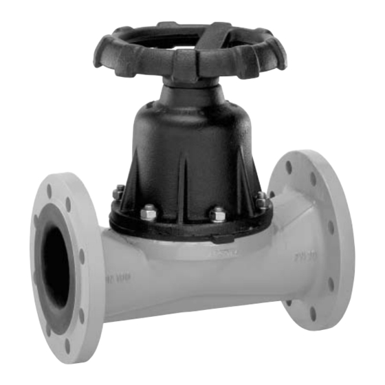
- Seite 1 GEMÜ 655 Manuell betätigtes Tiefsitz-Membranventil Manually operated full bore diaphragm valve Betriebsanleitung Operating instructions Weitere Informationen Webcode: GW-655...
- Seite 2 Alle Rechte, wie Urheberrechte oder gewerbliche Schutzrechte, werden ausdrücklich vorbehalten. All rights including copyrights or industrial property rights are expressly reserved. Dokument zum künftigen Nachschlagen aufbewahren. Keep the document for future reference. © GEMÜ Gebr. Müller Apparatebau GmbH & Co. KG 09.06.2021 GEMÜ 655 2 / 60 www.gemu-group.com...
-
Seite 3: Inhaltsverzeichnis
Membrane demontieren ........24 14.3 Membran montieren ........... 24 14.4 Antrieb montieren ..........26 16 Ausbau aus Rohrleitung ..........29 17 Entsorgung ............... 29 18 Rücksendung ............29 19 Konformitätserklärung nach 2014/68/EU (Druckgerä- terichtlinie) ............... 30 www.gemu-group.com 3 / 60 GEMÜ 655... -
Seite 4: Allgemeines
Warnhinweise sind dabei immer mit einem Signalwort und teilweise auch mit einem gefahrenspezifischen Symbol ge- kennzeichnet. Folgende Signalwörter bzw. Gefährdungsstufen werden einge- setzt: GEFAHR Unmittelbare Gefahr! ▶ Bei Nichtbeachtung drohen schwerste Verletzungen oder Tod. GEMÜ 655 4 / 60 www.gemu-group.com... -
Seite 5: Sicherheitshinweise
Auskleidung kument beschrieben sind, nicht ohne vorherige Abstim- mung mit dem Hersteller durchführen. 3.2 Beschreibung Das 2/2-Wege-Membranventil GEMÜ 655 verfügt über ein Me- Bei Unklarheiten: tall-Handrad und wird manuell betätigt. Der Ventilkörper ist in 15. Bei nächstgelegener GEMÜ-Verkaufsniederlassung nach- Tiefsitzausführung gefertigt. -
Seite 6: Funktion
Das Produkt ist für den Einbau in Rohrleitungen und zur Steue- rung eines Betriebsmediums konzipiert. Das Produkt ist bestimmungsgemäß nicht für den Einsatz in explosionsgefährdeten Bereichen geeignet. ● Das Produkt gemäß den technischen Daten einsetzen. GEMÜ 655 6 / 60 www.gemu-group.com... -
Seite 7: Bestelldaten
7 Flansch ANSI Class 125/150 FF, Baulänge FTF EN 558 Reihe 7, ISO 5752, basic se- ries 7 5 Werkstoff Ventilkörper Code Graugussmaterial EN-GJL-250 (GG 25) EN-GJL-250 (GG 25), Hartgummi-Auskleidung EN-GJL-250 (GG 25), Weichgummi-Auskleidung www.gemu-group.com 7 / 60 GEMÜ 655... -
Seite 8: Bestellbeispiel
Flansch EN 1092, PN 16, Form A, Baulänge FTF EN 558 Reihe 7, ISO 5752, basic series 7 5 Werkstoff Ventilkörper EN-GJL-250 (GG 25) 6 Membranwerkstoff EPDM 7 Steuerfunktion manuell betätigt 8 Antriebsausführung Antriebsgröße 4, für DN 50 und 65 GEMÜ 655 8 / 60 www.gemu-group.com... -
Seite 9: Technische Daten
Betriebsdruck bei geschlossenem Ventil ermittelt. Für die angegebenen Werte ist die Dichtheit am Ventil- sitz und nach außen gewährleistet. Angaben zu beidseitig anstehenden Betriebsdrücken und für Reinstmedien auf Anfrage. Ventil nicht geeignet für Vakuumanwendungen. www.gemu-group.com 9 / 60 GEMÜ 655... - Seite 10 Membranen den Einflüssen von Druck, Temperatur, des Prozesses und den Drehmo- menten mit denen diese angezogen werden. Dadurch können die Kv-Werte über die Toleranzgrenze der Norm hinaus abweichen. Die Kv-Wert-Kurve (Kv-Wert in Abhängigkeit vom Ventilhub) kann je nach Membranwerkstoff und Einsatzdauer variieren. GEMÜ 655 10 / 60 www.gemu-group.com...
-
Seite 11: Produktkonformitäten
EAC: TR CU 010/2011 7.5 Mechanische Daten Gewicht: Antrieb Antriebsausführung Gewicht 13,0 34,0 55,0 97,0 222,0 Gewichte in kg Körper Gewicht 12,0 17,1 28,4 31,9 76,6 99,2 181,6 MG = Membrangröße, Gewichte in kg www.gemu-group.com 11 / 60 GEMÜ 655... -
Seite 12: Abmessungen
3" - 4" 229,0 238,0 125 - 150 5" - 6" 307,0 316,0 8" 359,0 416,0 10" 484,0 416,0 12" 562,0 700,0 Maße in mm, MG = Membrangröße * CT = A + H1 (siehe Körpermaße) GEMÜ 655 12 / 60 www.gemu-group.com... -
Seite 13: Körpermaße
Code 4: Flansch EN 1092, PN 10, Form B, Baulänge FTF EN 558 Reihe 1, ISO 5752, basic series 1 2) Werkstoff Ventilkörper Code 82: EN-GJS-400-18-LT (GGG 40.3), Weichgummi-Auskleidung Code 83: EN-GJS-400-18-LT (GGG 40.3), Hartgummi-Auskleidung Code 88: EN-GJS-400-18-LT (GGG 40.3), Butyl-Auskleidung www.gemu-group.com 13 / 60 GEMÜ 655... - Seite 14 Code 8: Flansch EN 1092, PN 16, Form B, Baulänge FTF EN 558 Reihe 1, ISO 5752, basic series 1 2) Werkstoff Ventilkörper Code 82: EN-GJS-400-18-LT (GGG 40.3), Weichgummi-Auskleidung Code 83: EN-GJS-400-18-LT (GGG 40.3), Hartgummi-Auskleidung Code 88: EN-GJS-400-18-LT (GGG 40.3), Butyl-Auskleidung GEMÜ 655 14 / 60 www.gemu-group.com...
- Seite 15 Code 13: EN-GJL-250 (GG 25), Hartgummi-Auskleidung Code 16: EN-GJS-500-7 (GGG 50), Hartgummi-Auskleidung Code 52: EN-GJL-250 (GG 25), Weichgummi-Auskleidung Code 58: EN-GJL-250 (GG 25), Butyl-Auskleidung Code 92: EN-GJS-500-7 (GGG 50), Weichgummi-Auskleidung Code 98: EN-GJS-500-7 (GGG 50), Butyl-Auskleidung www.gemu-group.com 15 / 60 GEMÜ 655...
- Seite 16 Code 53: Flansch EN 1092, PN 16, Form A, Baulänge FTF EN 558 Reihe 7, ISO 5752, basic series 7 2) Werkstoff Ventilkörper Code 8: EN-GJL-250 (GG 25) Code 16: EN-GJS-500-7 (GGG 50), Hartgummi-Auskleidung Code 92: EN-GJS-500-7 (GGG 50), Weichgummi-Auskleidung Code 98: EN-GJS-500-7 (GGG 50), Butyl-Auskleidung GEMÜ 655 16 / 60 www.gemu-group.com...
- Seite 17 Code 39: Flansch ANSI Class 125/150 RF, Baulänge FTF EN 558 Reihe 1, ISO 5752, basic series 1 2) Werkstoff Ventilkörper Code 82: EN-GJS-400-18-LT (GGG 40.3), Weichgummi-Auskleidung Code 83: EN-GJS-400-18-LT (GGG 40.3), Hartgummi-Auskleidung Code 88: EN-GJS-400-18-LT (GGG 40.3), Butyl-Auskleidung 3) nicht nach ASME Standard www.gemu-group.com 17 / 60 GEMÜ 655...
- Seite 18 Code 13: EN-GJL-250 (GG 25), Hartgummi-Auskleidung Code 16: EN-GJS-500-7 (GGG 50), Hartgummi-Auskleidung Code 52: EN-GJL-250 (GG 25), Weichgummi-Auskleidung Code 58: EN-GJL-250 (GG 25), Butyl-Auskleidung Code 92: EN-GJS-500-7 (GGG 50), Weichgummi-Auskleidung Code 98: EN-GJS-500-7 (GGG 50), Butyl-Auskleidung GEMÜ 655 18 / 60 www.gemu-group.com...
-
Seite 19: Abmessungen Membrane
30° 25° 20° 12” 528,0 576,0 22,0 12,0 25,0 1” 280,0 18° 24° 24° 24° Maße in mm, MG = Membrangröße n = Anzahl der Schrauben Das Gewinde des Membranpins entspricht dem Whitworth Standard. www.gemu-group.com 19 / 60 GEMÜ 655... -
Seite 20: Herstellerangaben
13. Das Produkt nur zwischen zueinander passenden, fluch- tenden Rohrleitungen montieren (siehe nachfolgende Ka- pitel). 14. Durchflussrichtung beachten (siehe Kapitel „Durchfluss- richtung“). 15. Einbaulage beachten (siehe Kapitel „Einbaulage“). WARNUNG Aggressive Chemikalien! ▶ Verätzungen. Geeignete Schutzausrüstung tragen. ● Anlage vollständig entleeren. ● GEMÜ 655 20 / 60 www.gemu-group.com... -
Seite 21: Einbaulage
Das Produkt nicht als Trittstufe oder Steighilfe benutzen. ● 10.2 Einbaulage Die Einbaulage des Produkts ist beliebig. 10.3 Einbau mit Flanschanschluss Abb. 1: Flanschanschluss HINWEIS Dichtmittel! ▶ Das Dichtmittel ist nicht im Lieferumfang enthalten. Nur geeignetes Dichtmittel verwenden. ● www.gemu-group.com 21 / 60 GEMÜ 655... -
Seite 22: Inbetriebnahme
2. Bei neuen Anlagen und nach Reparaturen Leitungssystem spülen (das Produkt muss vollständig geöffnet sein). ð Schädliche Fremdstoffe wurden entfernt. ð Das Produkt ist einsatzbereit. 3. Das Produkt in Betrieb nehmen. 4. Inbetriebnahme der Antriebe gemäß beiliegender Anlei- tung. GEMÜ 655 22 / 60 www.gemu-group.com... -
Seite 23: Fehlerbehebung
Gewindeanschlüsse / Verschraubungen Gewindeanschlüsse / Verschraubungen lose festziehen Dichtmittel defekt Dichtmittel ersetzen Ventilkörper undicht Ventilkörper undicht oder korrodiert Ventilkörper auf Beschädigungen prüfen, ggf. Ventilkörper tauschen Handrad lässt sich nicht drehen Handrad defekt Handrad austauschen www.gemu-group.com 23 / 60 GEMÜ 655... -
Seite 24: Inspektion Und Wartung
3. Antrieb A vom Ventilkörper 1 abheben. 4. Antrieb A in Geschlossen-Position bringen. 5. Alle Teile von Verschmutzungen reinigen (Teile dabei nicht beschädigen). 6. Teile auf Beschädigung prüfen, ggf. auswechseln (nur Ori- ginalteile von GEMÜ verwenden). GEMÜ 655 24 / 60 www.gemu-group.com... - Seite 25 DN 80 – 100: Druckstück und Antriebsflansch von unten gesehen: Druckstück und Antriebsflansch von unten gesehen: DN 50 – 65: Druckstück und Antriebsflansch von unten gesehen: DN 125 – 150: Druckstück und Antriebsflansch von unten gesehen: www.gemu-group.com 25 / 60 GEMÜ 655...
-
Seite 26: Tiefsitzmembrane Montieren
Schrauben und Muttern spätestens nach dem ersten Ste- ● rilisationsprozess nachziehen. 1. Antrieb A in Offen-Position bringen. 2. Antrieb A mit montierter Membrane auf Ventilkörper auf- setzen. 3. Schrauben, Scheiben und Muttern handfest einschrauben. GEMÜ 655 26 / 60 www.gemu-group.com... - Seite 27 7. Auf gleichmäßige Verpressung der Membrane achten (ca. 10 bis 15 %). ð Gleichmäßige Verpressung ist an gleichmäßiger Au- ßenwölbung erkennbar. 8. Komplett montiertes Ventil auf Funktion und Dichtheit prü- fen. 9. Initialisierung durchführen. www.gemu-group.com 27 / 60 GEMÜ 655...
- Seite 28 15 Ersatzteile 15 Ersatzteile Handrad Leckagebohrung Position Benennung Bestellbezeichnung Ventilkörper K655… Tiefsitzmembrane 655…M… Schraube Scheibe 655...S30... Mutter Antrieb 9655... GEMÜ 655 28 / 60 www.gemu-group.com...
-
Seite 29: Ausbau Aus Rohrleitung
Entsorgung. Medien achten. 1. Das Produkt reinigen. 2. Alle Teile entsprechend den Entsorgungsvorschriften / 2. Rücksendeerklärung bei GEMÜ anfordern. Umweltschutzbedingungen entsorgen. 3. Rücksendeerklärung vollständig ausfüllen. 4. Das Produkt mit ausgefüllter Rücksendeerklärung an GEMÜ schicken. www.gemu-group.com 29 / 60 GEMÜ 655... -
Seite 30: Konformitätserklärung Nach 2014/68/Eu (Druckgeräterichtlinie)
Wir, die Firma GEMÜ Gebr. Müller Apparatebau GmbH & Co. KG Fritz-Müller-Straße 6-8 D-74653 Ingelfingen-Criesbach erklären, dass das unten aufgeführte Produkt die Sicherheitsanforderungen der Druckgeräterichtlinie 2014/68/EU erfüllt. Benennung des Druckgerätes: GEMÜ 655 Benannte Stelle: TÜV Rheinland Industrie Service GmbH Nummer: 0035 Zertifikat-Nr.: 01 202 926/Q-02 0036 Konformitätsbewertungsverfahren:... - Seite 58 GEMÜ 655 58 / 60 www.gemu-group.com...
- Seite 59 59 / 60 GEMÜ 655...
- Seite 60 Änderungen vorbehalten GEMÜ Gebr. Müller Apparatebau GmbH & Co. KG Subject to alteration *88262452* Fritz-Müller-Straße 6–8, 74653 Ingelfingen-Criesbach, Germany 06.2021 | 88262452 Phone +49 (0) 7940 1230 · info@gemue.de www.gemu-group.com...