Gemü 655 Original Einbau- Und Montageanleitung
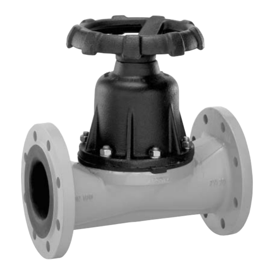
Tiefsitzmembranventil
Vorschau ausblenden
Andere Handbücher für 655:
- Betriebsanleitung (60 Seiten) ,
- Original einbau- und montageanleitung (32 Seiten) ,
- Betriebsanleitung (30 Seiten)

Verwandte Anleitungen für Gemü 655


Inhaltszusammenfassung für Gemü 655
- Seite 1 Tiefsitzmembranventil Metall, DN 25 - 300 Full Bore Diaphragm Valve Metal, DN 25 - 300 ORIGINAL EINBAU- UND MONTAGEANLEITUNG INSTALLATION, OPERATING AND MAINTENANCE INSTRUCTIONS...
-
Seite 2: Inhaltsverzeichnis
Inhaltsverzeichnis Allgemeine Hinweise Voraussetzungen für die einwandfreie Allgemeine Hinweise Funktion des GEMÜ-Ventils: Allgemeine Sicherheitshinweise 2 Sachgerechter Transport und Lagerung Hinweise für Service- Installation und Inbetriebnahme durch und Bedienpersonal eingewiesenes Fachpersonal Warnhinweise Bedienung gemäß dieser Einbau- und Verwendete Symbole Montageanleitung Begriff sbestimmungen Ordnungsgemäße Instandhaltung Vorgesehener Einsatzbereich Technische Daten... -
Seite 3: Hinweise Für Service
Hinweise für Service- Warnhinweise und Bedienpersonal Warnhinweise sind, soweit möglich, nach Die Einbau- und Montageanleitung enthält folgendem Schema gegliedert: grundlegende Sicherheitshinweise, die bei SIGNALWORT Inbetriebnahme, Betrieb und Wartung zu beachten sind. Nichtbeachtung kann zur Art und Quelle der Gefahr Folge haben: ®... -
Seite 4: Verwendete Symbole
Verwendete Symbole Vorgesehener Einsatzbereich Das Tiefsitzmembranventil GEMÜ 655 Gefahr durch heiße Oberfl ächen! ist für den Einsatz in Rohrleitungen konzipiert. Es steuert ein durchfl ießendes Medium durch Handbetätigung. Gefahr durch ätzende Stoff e! Das Ventil darf nur gemäß den technischen Daten eingesetzt werden Quetschgefahr! (siehe Kapitel 5 "Technische Daten"). -
Seite 5: Bestelldaten
Bestelldaten Gehäuseform Code Membranwerkstoff Code Durchgang Anschlussart Code EPDM Flansch EN 1092 / PN10 / Form A, Baulänge FTF EN 558, Reihe 7, ISO 5752, basic series 7 Flansch EN 1092 / PN16 / Form A, Steuerfunktion Code Baulänge FTF EN 558, Reihe 7, ISO 5752, basic series 7 Manuell betätigt Flansch ANSI Class 125/150 FF,... -
Seite 6: Herstellerangaben
Herstellerangaben Funktionsbeschreibung Das handgesteuerte 2/2-Wege- Tiefsitzmembranventil GEMÜ 655 mit Transport Metallantrieb besitzt ein nichtsteigendes Handrad. Ventilkörper und Membrane Ventil nur auf geeignetem Lademittel transportieren, nicht stürzen, vorsichtig sind gemäß Datenblatt in verschiedenen Ausführungen erhältlich. Das Ventil handhaben. ist nachträglich umrüstbar auf... -
Seite 7: Montage Und Bedienung
10 Montage und Bedienung Installationsort: Vor Einbau: VORSICHT Ventilkörper- und Membranwerkstoff Ventil äußerlich nicht stark entsprechend Betriebsmedium auslegen. beanspruchen. Eignung vor Einbau prüfen! Installationsort so wählen, dass Ventil Siehe Kapitel 5 "Technische Daten". nicht als Steighilfe genutzt werden kann. Rohrleitung so legen, dass Schub- und 10.1 Montage des Ventils Biegungskräfte, sowie Vibrationen und Spannungen vom Ventilkörper... -
Seite 8: Montage / Demontage Von Ersatzteilen
11.1 Demontage Ventil Montage bei Flanschanschluss: (Antrieb vom Körper lösen) 1. Auf saubere und unbeschädigte Dichtfl ächen der Anschlussfl ansche 1. Antrieb A in Off en-Position bringen. achten. 2. Antrieb A vom Ventilkörper 1 2. Flansche vor Verschrauben sorgfältig demontieren. ausrichten. -
Seite 9: Montage Membrane
11.3 Montage Membrane DN 25 - 40: Druckstück und Antriebsflansch von unten gesehen: 11.3.1 Allgemeines Wichtig: Für Ventil passende Membrane einbauen (geeignet für Medium, Mediumkonzentration, Temperatur und Druck). Die Membrane ist ein Verschleißteil. DN 50 - 65: Vor Inbetriebnahme und über Druckstück und Antriebsflansch von unten gesamte Einsatzdauer des Ventils gesehen:... -
Seite 10: Montage Der Tiefsitzmembrane
11.3.2 Montage der DN 200: Tiefsitzmembrane Druckstück und Antriebsflansch von unten gesehen: Wichtig: Für Ventil passende Membrane einbauen (geeignet für Medium, Mediumkonzentration, Temperatur und Druck). DN 250: 1. Vor Montage der neuen Membrane Druckstück und Antriebsflansch von unten Antrieb demontieren wie unter gesehen: Kapitel 11.2 "Demontage Membrane"... -
Seite 11: Inbetriebnahme
Reinigung: Betreiber der Anlage ist verantwortlich für Auswahl des Reinigungsmediums und Durchführung des Verfahrens. 6. Auf gleichmäßige Verpressung der 13 Inspektion und Wartung Membrane 2 achten (ca. 10 - 15 %, erkennbar an gleichmäßiger WARNUNG Außenwölbung). 7. Komplett montiertes Ventil auf Dichtheit Unter Druck stehende Armaturen! prüfen. -
Seite 12: Demontage
14 Demontage 17 Hinweise Demontage erfolgt unter den gleichen Hinweis zur Vorsichtsmaßnahmen wie die Montage. Mitarbeiterschulung: Ventil demontieren (siehe Kapitel 11.1 Zur Mitarbeiterschulung nehmen "Demontage Ventil (Antrieb vom Körper Sie bitte über die Adresse auf der lösen)"). letzten Seite Kontakt auf. Im Zweifelsfall oder bei Missverständnissen 15 Entsorgung ist die deutsche Version des Dokuments... -
Seite 13: Fehlersuche / Störungsbehebung
18 Fehlersuche / Störungsbehebung Fehler Möglicher Grund Fehlerbehebung Betriebsmedium entweicht Membrane auf Beschädigungen prüfen, Membrane defekt aus Leckagebohrung* ggf. Membrane tauschen Antrieb demontieren, Membranmontage Membrane nicht korrekt montiert Ventil öffnet nicht bzw. nicht prüfen, ggf. austauschen vollständig Antrieb defekt Antrieb austauschen Ventil mit Betriebsdruck laut Datenblatt Betriebsdruck zu hoch betreiben... -
Seite 14: Schnittbild Und Ersatzteile
19 Schnittbild und Ersatzteile Handrad Leckagebohrung Pos. Benennung Bestellbezeichnung Ventilkörper K655… Tiefsitzmembrane 655…M… Schraube Scheibe 655...S30... Mutter Antrieb 9655... 14 / 32... -
Seite 15: Eu-Konformitätserklärung
GEMÜ Gebr. Müller Apparatebau GmbH & Co. KG Fritz-Müller-Straße 6-8 D-74653 Ingelfingen erklären, dass unten aufgeführte Armaturen die Sicherheitsanforderungen der Druckgeräte- richtlinie 2014/68/EU erfüllen. Benennung der Armaturen - Typenbezeichnung Tiefsitzmembranventil GEMÜ 655 Benannte Stelle: TÜV Rheinland Industrie Service GmbH Nummer: 0035 Zertifikat-Nr.: 01 202 926/Q-02 0036... - Seite 30 30 / 32...
- Seite 31 31 / 32...
- Seite 32 GEMÜ Gebr. Müller Apparatebau GmbH & Co. KG · Fritz-Müller-Str. 6-8 · D-74653 Ingelfi ngen-Criesbach Telefon +49(0)7940/123-0 · Telefax +49(0)7940/123-192 · info@gemue.de · www.gemu-group.com...