Inhaltsverzeichnis
Werbung
Verfügbare Sprachen
Verfügbare Sprachen
Quicklinks
Werbung
Kapitel
Inhaltsverzeichnis

Verwandte Anleitungen für B. Braun Aesculap ElanEC GA835


Inhaltszusammenfassung für B. Braun Aesculap ElanEC GA835
- Seite 1 Service-Manual ElanEC GA835, GA830 Service-Manual ElanEC GA835, GA830 B|BRAUN...
- Seite 2 Deutsch Seite 1-17 English Page 18-34...
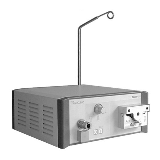
- Seite 4 Anschlussstelle für Potentialausgleichsleitung gung vor! Sicherungshalter mit Spannungswahleinsatz Ø Für Service, Wartung und Reparatur wenden Sie sich Gerätesteckdose an Ihre nationale AESCULAP/B. Braun-Vertretung. Aufnahme des Haltearms für die Biegewelle Ø Bei Modifikationen an medizintechnischer Ausrüs- tung erlischt der Garantieanspruch sowie eventuelle Zulassungen.
-
Seite 5: Inhaltsverzeichnis
ELANEC GA830 / GA835 Inhaltsverzeichnis Mess- und Prüfmittel............3 Öffnen bzw. Schließen des Gerätes ......3 Öffnen des Gerätes ............3 Schließen des Gerätes............. 3 Sichtkontrolle ..............4 Schäden durch Desinfektionsmittel, UV-Strahlen u.a..................4 3.1.1 Verdrahtung..............4 3.1.2 Elektronikplatinen............4 3.1.3 Gehäuse ................ -
Seite 6: Verantwortlichkeit Des Herstellers Bei Instandsetzungen
ELANEC GA830 / GA835 Verantwortlichkeit des Herstellers bei In- Öffnen bzw. Schließen des Gerätes standsetzungen 7 7 7 7 Der Hersteller betrachtet sich nur dann verantwortlich für Warnhinweis: die Auswirkungen auf die Sicherheit, Zuverlässigkeit und Leistung des Gerätes, wenn Ø Vor Öffnen des Gerätes Netzstecker ziehen, da Ø... -
Seite 7: Sichtkontrolle
ELANEC GA830 / GA835 3.1.2 Elektronikplatinen Sichtkontrolle Zeigen die Platinen Korrosion, oder andere Beschädi- gungen an Kontakten oder Lötstellen, sind sie aus Grün- 7 7 7 7 den der Gerätesicherheit auszutauschen. Achtung! Nach erfolgtem Leiterplattenwechsel müssen sämtliche Steckverbindungen wieder sorgfältig zusammengeführt Ø... -
Seite 8: Spannungsvorwahl
ELANEC GA830 / GA835 Spannungsvorwahl Grundfunktionstest 7 7 7 7 Vorbereitung Achtung! Ø Die folgenden Arbeiten dürfen nur bei gezogenem Siehe hierzu auch Gebrauchsanweisung Netzstecker erfolgen, da berührbare Teile lebens- Sicherstellen, dass das zum Test verwendete Zubehör gefährliche Netzspannungen führen können. einwandfrei funktioniert. -
Seite 9: Technische Funktionsbeschreibung
ELANEC GA830 / GA835 Technische Funktionsbeschreibung Allgemeine Hinweise Bei Verwendung einer Mikrobiegewelle ist ein Arbeiten Die Funktionsbeschreibung erläutert Funktionen der ein- im Rechts- und Linkslauf möglich. Die maximale Drehzahl zelnen Schaltungsteile und deren Zusammenwirken. beträgt 20000 1/min. Im Linkslauf gibt das Gerät einen Soweit möglich sind abgeschlossene Funktionseinheiten Signalton ab. -
Seite 10: Blockschaltbild
ELANEC GA830 / GA835 Blockschaltbild... -
Seite 11: Technische Beschreibung Der Baugruppen
ELANEC GA830 / GA835 Technische Beschreibung der Baugruppen Grundplatte GA835810 8.1.1 Bestückungsplan Netzpotential behaftet Netzpotential frei... -
Seite 12: Steckerreferenz
ELANEC GA830 / GA835 8.1.2 Steckerreferenz BREAK MP37 Stecker P1: MP38 MP39 PIN Signalname START NETZ-10 NETZ-6 Stecker P7: NETZ-9 NETZ-7 PIN Signalname NETZ-8 NETZ-5 PUMPE1/0 RE/LI Stecker P2: FUSSPOT-S FUSSPOT-E PIN Signalname NETZ-3 Stecker P8: NETZ-4 NS14 PIN Signalname NS44 +12V LEDP-K... -
Seite 13: Funktionen Der Grundplatte
ELANEC GA830 / GA835 FUSSPOT-E 8.1.3 Funktionen der Grundplatte MP 8 Die Grundplatte ist räumlich und potentialmäßig in zwei MP 9 Bereiche aufgeteilt. MP10 1.) Netzpotentialfreier Teil mit folgenden Schaltungs- teilen: Stecker P13: a.) Stromversorgung (Tr1, F1, GL2, U1) PIN Signalname b.) Ansteuerung der Anzeigen "Rechtslauf", "Links- MP11 lauf"... - Seite 14 ELANEC GA830 / GA835 Zu b) Stromversorgung der Steuerung und Regelung und Sourceanschlüssen gemessen werden. Der Wert sollte bei intakten FET´s bei ca. 2M Ω oder höher liegen. Die gleichgerichtete Sekundärspannung von Tr2 wird dem Durchlegierte Fet´s haben einen deutlich geringeren Wi- Schaltregler U2 zur Erzeugung einer stabilisierten derstandswert ( <...
-
Seite 15: Pumpensteuerung Ga835801
ELANEC GA830 / GA835 Pumpensteuerung GA835801 8.2.1 Bestückungsplan 8.2.2 Steckerreferenz Stecker P3: Stecker P1: PIN Signalname PPOTI-E PIN Signalname PPOTI-S +22V PUMPE1/0 MOTOR-1 PUMPSTART MOTOR-2 +12V Stecker P2: PIN Signalname +22V-S PPOTI-S TP10... -
Seite 16: Funktion
ELANEC GA830 / GA835 8.2.3 Funktion Sicherungswechsel Kühlmittelpumpe wird durch Steckkarte GA835801 gesteuert und geregelt. 7 7 7 7 Aktiviert wird die ganze Leiterplatte durch den Schalter Achtung! "Pumpe-Ein" am Fußregler UND durch die Pedalbetäti- gung zur Steuerung des EC-Motors. Ø... -
Seite 17: Verdrahtungsplan
ELANEC GA830 / GA835 10 Verdrahtungsplan... -
Seite 18: Reparatur Der Kühlflüssigkeitspumpe
ELANEC GA830 / GA835 11.2 Auswechseln des Pumpenmotors 11 Reparatur der Kühlflüssigkeitspumpe Ø Pumpenoberteil und Rotor entfernen., siehe Aus- 11.1 Auswechseln der Pumpenfedern wechseln der Pumpenfedern. Ø Abdeckkappen entfernen. Ø Darunter liegende Schrauben lösen. Ø Pumpenoberteil nach vorne abziehen. Ø Abdeckkappen entfernen. Ø... -
Seite 19: Endkontrolle
ELANEC GA830 / GA835 12 Endkontrolle 12.2 Messung des Ersatzgeräteableitstromes Messung des Ersatzgeräteableitstromes Erforderliche Testgeräte: Sicherheitstester Maximalwert: 0.75 mA z. B. RIGEL Sicherheitstester 233 GERB Sicherheitstester GM-200 Berührbare, leitfähige Teile (Gerätegehäuse) Wurden an einem geöffneten Gerät irgendwelche Geräteanschlussleitung Reparaturen, z. B. in Form eines Leiterplattenwechsels (Netzteil) etc. -
Seite 20: Ersatzteilliste
ELANEC GA830 / GA835 13 Ersatzteilliste Steuergerät Aesculap Art.-Nr. Bezeichnung GA835810 Leiterplatte Grundplatte GA835820 Leiterplatte Anzeige GA835802 Leiterplatte Filter Leiterplatte Pumpensteuerung GA835801 * GA830830 Motor komplett Pumpenmotor GD412221 * TA021796 Lüfter GA830220 Folientastatur Folientastatur GA835220 * GA840221 Rückplatte TA021401 Netzfilter TA021230 Spannungswahleinsatz TA021396... - Seite 21 Fuse holder including voltage selection insert Ø For service, maintenance and repairs, contact the Power plug socket AESCULAP/B. Braun representative in your country. Flexible shaft support connection Ø All guarantees and warranty rights as well as licenses will be voided if modifications on the unit are performed.
- Seite 22 ELANEC GA830 / GA835 Contents Measuring and test equipment........20 Opening and closing the device.........20 Opening the device............20 Closing the device............20 Visual inspection ............21 Damage caused by disinfecting agents, UV radiation, etc..............21 3.1.1 Wiring ................21 3.1.2 Electronic boards............21 3.1.3 Housing................21 Mechanical damage ............21 Putting the device into operation ......21 Selection of voltage............22...
-
Seite 23: Responsibility Of Manufacturer In Case Of Repair
ELANEC GA830 / GA835 Responsibility of manufacturer in case of Opening and closing the device repair 7 7 7 7 The manufacturer shall only be responsible for the effects Warning: on the safety, reliability and performance of the device, if Ø... -
Seite 24: Visual Inspection
ELANEC GA830 / GA835 be replaced to ensure the safe operation of the device. Visual inspection After replacing the board, all plug-in connections must be carefully re-connected and the board catch must be closed again. 7 7 7 7 Caution! 3.1.3 Housing Ø... -
Seite 25: Selection Of Voltage
ELANEC GA830 / GA835 Selection of voltage Basic function test 7 7 7 7 Preparation Caution! Ø The following work may only be carried out after See also Instructions for Use the device has been disconnected from the mains, Ensure that the accessories used for the test function as contact parts may contain hazardous voltages. -
Seite 26: Description Of Technical Function
ELANEC GA830 / GA835 Description of technical function General information Where an micro-flexible shaft is used, the motor can be The functional description explains the functions of the operated with both clockwise and counterclockwise individual circuit subassemblies and their cooperation. torqueat a maximum speed of 20000 rpm. -
Seite 27: Block Diagram
ELANEC GA830 / GA835 Block diagram... -
Seite 28: Technical Description Of Subassemblies
ELANEC GA830 / GA835 Technical description of subassemblies Motherboard GA835810 8.1.1 Component mounting diagram Mains potential assigned Mains potential not assigned... -
Seite 29: Connector Reference
ELANEC GA830 / GA835 8.1.2 Connector reference MP33 MP34 POT. S Connector P1: BREAK MP37 PIN Signal name MP38 MAINS 10 MP39 MAINS 6 START MAINS 9 MAINS 7 Connector P7: MAINS 8 MAINS 5 PIN Signal name Connector P2: PUMP1/0 RE/LI PIN Signal name... -
Seite 30: Functions Of Motherboard
ELANEC GA830 / GA835 +12V 8.1.3 Functions of motherboard The motherboard is divided into two physical and RE/LI potential areas. FOOT POT. E 1.) Non-live part incl. following circuit MP 8 components: MP 9 MP10 a.) Power supply (Tr1, F1, GL2, U1) b.) Control of "Clockwise", "Counterclockwise"... - Seite 31 ELANEC GA830 / GA835 FETs, a value of approx. 2M Ω or higher should be re. b) Power supply of controls and regulating unit measured. The rectified secondary voltage from Tr2 is forwarded to The resistance of failed Fets is considerably lower the switching controller U2 in order to generate a ( <...
-
Seite 32: Pump Controls Ga835801
ELANEC GA830 / GA835 Pump controls GA835801 8.2.1 Component mounting diagram 8.2.2 Connector reference TP10 Connector P1: Connector P3: PIN Signal name PIN Signal name +22V PPOT. E PUMP 1/0 PPOT. S PUMPSTART +12V MOTOR 1 MOTOR 2 Connector P2: PIN Signal name +22V-S PPOT. -
Seite 33: Function
ELANEC GA830 / GA835 8.2.3 Function Changing fuses The coolant pump is controlled and regulated by card GA835801. 7 7 7 7 The entire board is activated by the "Pump on" switch on Caution! the foot controller AND the pedal activation for controlling the EC motor. -
Seite 34: Wiring Diagram
ELANEC GA830 / GA835 10 Wiring diagram... -
Seite 35: Repairing The Coolant Pump
ELANEC GA830 / GA835 11.2 Replacing the pump motor 11 Repairing the coolant pump Ø Remove upper part of pump and rotor, see Replacing 11.1 Replacing the pump springs the pump springs. Ø Remove caps. Ø Remove the screws beneath the caps. Ø... -
Seite 36: Final Test
ELANEC GA830 / GA835 12 Final test 12.2 Measuring the equivalent unit leakage current Required test devices: safety tester i.e.. RIGEL Safety Tester 233 Measurement of the equivalent unit leakage current GERB Safety Tester GM-200 Maximum value: 0.75 mA Contactable, conductive parts Where any repair work such as replacement of printed (unit housing) boards, etc. -
Seite 37: Spare Parts List
ELANEC GA830 / GA835 13 Spare parts list Control unit Aesculap item no. Name GA835810 Motherboard GA835820 Display board GA835802 Filter board Pump control board GA835801 * GA830830 Motor - complete Pump motor GD412221 * TA021796 GA830220 Membrane keyboard Membrane keyboard GA835220 * GA840221 Back panel... - Seite 38 Technische Änderungen vorbehalten CE-Kennzeichnung gemäß Richtlinie 93/42/EWG AESCULAP & CO. KG Am Aesculap-Platz 78532 Tuttlingen/ Germany Telefon (07461) 95-0 Telefax (07461) 95-26 00 B|BRAUN TA-Nr. 022046 09/01...