Inhaltsverzeichnis
Werbung
Verfügbare Sprachen
Verfügbare Sprachen
Quicklinks
Werbung
Inhaltsverzeichnis

Verwandte Anleitungen für Gicam RQA


Inhaltszusammenfassung für Gicam RQA
- Seite 1 Manuale Manual Handbuch ...
- Seite 2 Manuale d’istallazione e d’uso Installation and user manual Installations- und Bedienungsanleitung Amplificatore digitale/analogico per celle di carico Digital/analog load cell amplifier Digital/Analog-Verstärker für Wägezellen ...
-
Seite 3: Inhaltsverzeichnis
Indice / Table of contents / Inhaltsverzeichnis Indice / Table of contents / Inhaltsverzeichnis ..................1 Manuale d’installazione ..........................3 Caratteristiche tecniche ........................... 3 Simbologia ............................... 4 Avvertenze ............................... 4 Montaggio dello strumento ........................4 Targa identificativa dello strumento......................4 Alimentazione dello strumento ........................ - Seite 4 Installationsanleitung ..........................15 Technische Spezifikation ........................15 Symbole ..............................16 Warnungen ............................16 Installation des Gerätes ......................... 16 Typenschild des Gerätes ........................16 Stromversorgung des Instruments ......................17 Anschluss der Wägezellen ........................17 Anschluss der analogen Ausgänge ....................... 18 Anschlussübersicht ..........................18 Bedienungsanleitung ..........................
-
Seite 5: Manuale D'installazione
Manuale d’installazione Caratteristiche tecniche Alimentazione 24 V dc ± 10 % protetta contro l’inversione di polarità. Protezione con fusibile ripristinabile Assorbimento massimo 1 Watt Isolamento Classe II Categoria d’installazione Categoria II Temperatura di stoccaggio - 20 °C / + 60 °C Temperatura di funzionamento - 10 °C / + 50 °C Umidità... -
Seite 6: Simbologia
Simbologia Attenzione! Questa operazione deve essere eseguita da personale specializzato! Prestare particolare attenzione alle indicazioni seguenti Ulteriori informazioni Avvertenze Scopo del presente manuale è di portare a conoscenza dell’operatore con testi e figure di chiarimento, le prescrizioni ed i criteri fondamentali per l’installazione ed il corretto impiego dello strumento. ... -
Seite 7: Alimentazione Dello Strumento
Alimentazione dello strumento Lo strumento viene alimentato attraverso i morsetti 11 e 12. Il cavo di alimentazione deve essere incanalato separatamente da altri cavi di alimen- tazioni con tensioni diverse, dai cavi delle celle di carico, encoder e degli input/output logici e analogici. -
Seite 8: Connessione Uscita Analogica
Uscita analogica Lo strumento fornisce di serie un'uscita analogica sia in corrente che in tensione. Caratteristiche: Uscita analogica in tensione: range da -10 a +10 Volt oppure da -5 a +5 Volt, carico minimo 10 kΩ Uscita analogica in corrente: range da 0 a 20 mA oppure da 4 a 20 mA. Il carico massimo è 300 Ω. E possibile l’uscita 0-10 Volt oppure 0-5 Volt previa configurazione in fabbrica. -
Seite 9: Manuale D'uso
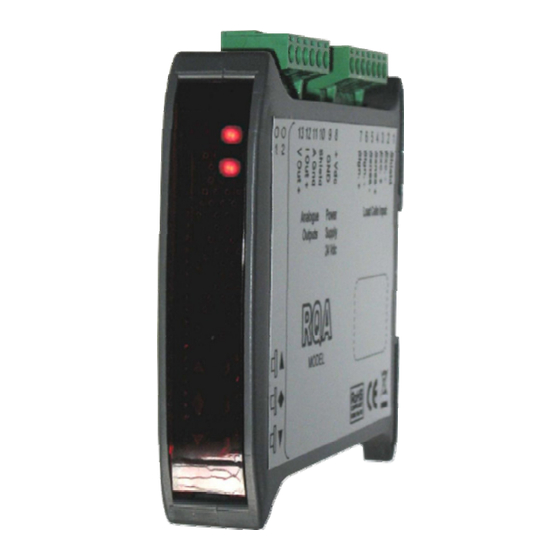
Manuale d’uso Principali caratteristiche d’uso Le caratteristiche principali di funzionamento sono la gestione di un’uscita analogica; l’uscita può essere sia Il panello frontale dello strumento Indicatori LED Lo strumento è provvisto di due indicatori LED: LED 1 LED 2 Stato dello strumento Acceso Spento Normale funzionamento... -
Seite 10: Funzioni Operative
Funzioni operative Impostazione filtro digitale Premere il tasto per 3 secondi per accedere all’impostazione del filtro digitale. ▲ Incrementa filtro Conferma e torna al normale funzionamento ▼ Decrementa filtro Quando si è all’interno della funzione di impostazione filtro, I LED sono entrambi accesi Premendo il tasto ▲... -
Seite 11: Installation Manual
Installation manual Technical specification Power supply 24 V direct current ± 10 % protected against inversion of polarity. Protection resettable fuse Maximum power consumption 1 Watt Insulation Class II Installation category Category II Storage temperature -4 °F / 140 °F Operating temperature 14 °F / 122 °F Humidity... -
Seite 12: Symbols
Symbols Attention! This operation has to be carried out by specialized personnel! Pay particolar attention to the follwoing indications! Further information Warnings The purpose of this manual is to bring to the operator's knowledge with clarification texts and figures, the requirements and the fundamental criteria for the installation and correct use of the instrument. -
Seite 13: Power Supply Of The Instrument
Power supply of the instrument The instrument is powered through terminals 11 and 12. The power supply cable must be channeled separately from other power supply cables with different voltages, from load cell cables, encoders and logical and analogue in- puts / outputs. -
Seite 14: Analog Outputs
Analogue outputs The instrument supplies an analog output in current and one in tension. Characteristics: Analog output in tension: range from -10 to +10 Volt or from -5 to +5 Volt, minimum load 10 kΩ Analog output in current: range from 0 to 20 mA or from 4 to 20 mA. The maximum load is 300Ω. It is possible to have an output 0-10 Volt or 0-5 Volt after previous configuration in the factory. -
Seite 15: User Manual
User manual Main characteristics of use The main operating features are the management of an analog output, the output can be either in Volt or in Front panel of the instrument LED indicators The instrument is equipped with two LED indicators: LED 1 LED 2 Status of the instrument... -
Seite 16: Operational Functions
Operational functions Digital filter setting Press the key for 3 seconds to access the digital filter settings. ▲ Increase filter Confirm and return to normal operation ▼ Decrease filter When you are inside the filter setting function, the LEDs are both lit Pressing the ▲... -
Seite 17: Installationsanleitung
Installationsanleitung Technische Spezifikation Stromversorgung 24 V Gleichstrom ± 10 % gegen Polaritätsumkehr geschützt. Schutz durch Sicherung Maximale Stromaufnahme 1 Watt Isolierung Klasse II Installationskategorie Kategorie II Lagertemperatur - 20 °C / + 60 °C Betriebstemperatur - 10 °C / + 50 °C Luftfeuchtigkeit Maximal 85% nicht kondensierend 2 LED mit 3 mm (Funktionsstatus) -
Seite 18: Symbole
Symbole Achtung! Dieser Vorgang muss von Fachpersonal ausgeführt werden! Beachten Sie besonders die folgenden Hinweise! Weiterführende Informationen Warnungen Zweck dieses Handbuchs ist es, den Bediener mit Erklärungen und Abbildungen über die grundlegenden Anforderungen und Kriterien für die Installation und den korrekten Gebrauch des Gerätes zu informieren. ... -
Seite 19: Stromversorgung Des Gerätes
Stromversorgung des Gerätes Das Gerät wird über die Klemmen 11 und 12 mit Strom versorgt. Das Stromversorgungskabel muss getrennt von anderen Stromkabeln mit unterschied- lichen Spannungen, Kabeln von Wäge-zellen und Logikein- / ausgängen verlegt wer- den. Der interne Stromkreis ist galvanisch von der Versorgungsspannung getrennt. Versorgungsspannung: 24 Volt Gleichstrom, ±... -
Seite 20: Anschluss Der Analogen Ausgänge
Anschluss der analogen Ausgänge Das Gerät stellt einen analogen Ausgang in Spannung und einen Ausgang in Strom zur Verfügung. Eigenschaften: Analogausgang in Spannung: Bereich von -10 bis +10 V oder von -5 bis +5 V, Minimallast 10 kΩ Analogausgang in Strom: Bereich von 0 bis 20 mA oder von 4 bis 20 mA. -
Seite 21: Bedienungsanleitung
Bedienungsanleitung Hauptbetriebsmerkmale Die wichtigste Betriebsfunktion ist die Verwaltung eines Analogausganges. Die Ausgabe kann entweder in Volt oder in mA erfolgen. Die Frontplatte des Gerätes LED Anzeigen Das Gerät ist mit zwei Anzeige-LED ausgestattet: LED 1 LED 2 Gerätestatus Normalbetrieb Blinkend Nullpunktkorrektur-Funktion des Analogausganges wird ausgeführt Blinkend Spankorrektur-Funktion des Analogausganges wird ausgeführt... -
Seite 22: Betriebsfunktionen
Betriebsfunktionen Einstellung Digitalfilter Drücken Sie die Taste für 3 Sekunden um zu den Einstellungen des Digitalfilters zu gelangen. ▲ Filter erhöhen Bestätigen und zum Normalbetrieb zurückkehren ▼ Filter verringern Wenn Sie sich in der Filtereinstellungsfunktion befinden, leuchten beide LEDs Durch Drücken der Taste ▲ wird der Gewichtsfilter erhöht (wählbar von 0 bis 9). Durch Drücken der Taste ▼... - Seite 23 Questo manuale è stato redatto con la massima cura ed al momento della pubblicazione è ritenuto privo di errori. GICAM si impegna di mantenere questo manuale sempre aggiornato e pubblicare versioni aggiornati sul suo sito web appena disponibile. Si declina ogni responsabilità per danni causati da errori in questo momento non identificati e si chiede di segnalare eventuali errori o incongruenze usando i nostri contatti indicati sul retro di questa copertina.