Inhaltsverzeichnis
Werbung
Verfügbare Sprachen
Verfügbare Sprachen
Quicklinks
Werbung
Inhaltsverzeichnis
Fehlerbehebung

Verwandte Anleitungen für Gicam RQ


Inhaltszusammenfassung für Gicam RQ
- Seite 1 Manuale Manual Handbuch ...
- Seite 2 Manuale d’istallazione e d’uso Manuale d’istallazione e d’uso Installa on and user manual Installa on and user manual Installa ons Installa ons – und Bedienungsanleitung und Bedienungsanleitung – AMPLIFICATORE digitale per celle di carico Digital load cell AMPLIFIER Digital VERSTÄRKER für Wägezellen ...
- Seite 3 Connessione seriale RS232 ........................11 Connessione uscite analogiche (solo versione RQ / ANA) ..............11 Connessione Ethernet (solo versione RQ / Ethernet e RQ / Ethernet IP) ..........12 Connessione ProfiBus (solo versione RQ / ProfiBus) ................13 Connessione ProfiNet (solo versione RQ / ProfiNet) ................13 Connessione Ethercat (solo versione RQ / Ethercat) ................
- Seite 4 Programmazione soglie di peso (solo RQ / ANA) ............... 37 Richiesta soglie di peso programmate (solo RQ / ANA) ............. 37 Comando di attivazione uscite logiche (solo RQ / ANA, se soglie programmate a 0) ....37 Richiesta stato ingressi logici (solo RQ / ANA) ................37 Comando di memorizzazione soglie in memoria permanente (solo RQ / ANA) ......
- Seite 5 Serial RS232 connection ........................53 Connection analog outputs (only RQ / ANA version) ................53 Ethernet connection (only RQ / Ethernet and RQ / Ethernet IP versions) ..........54 ProfiBus connection (only RQ / ProfiBus version) ................. 55 ProfiNet connection (only RQ / ProfiNet version) .................. 55 Ethercat connection (only RQ / Ethercat version) .................
- Seite 6 Weight threshold programming (only RQ / ANA) ................ 79 Request of programmed weight thresholds (only RQ / ANA) ............. 79 Logic output activation command (only RQ / ANA, if thresholds programmed at 0) ....79 Logic input status request (RQ / ANA only) ................79 Command to store thresholds in permanent memory (only RQ / ANA) ........
- Seite 7 Serieller RS232 Anschluss ........................95 Anschluss logische Ausgänge (nur Version RQ / ANA) ................ 95 Ethernet Anschluss (nur Versionen RQ / Ethernet und RQ / Ethernet IP) ..........96 ProfiBus Verbindung (nur Version RQ / ProfiBus) ................97 ProfiNet Verbindung (nur Version RQ / ProfiNet) .................. 97 Ethercat Verbindung (nur Version RQ / Ethercat) .................
- Seite 8 Befehl zur Aktivierung der Logikausgänge (nur RQ / ANA) ............121 Anforderung Zustand Logikeingänge (nur RQ / ANA) .............. 121 Befehl zur Speicherung der Schwellenwerte im permanenten Speicher (nur RQ / ANA) ..121 Beschreibung der Felder ......................121 MODUBS RTU / TCP Protokoll ...................... 122 Fehlerbehandlung von Kommunikationsfehlern ................
-
Seite 9: Manuale D'installazione
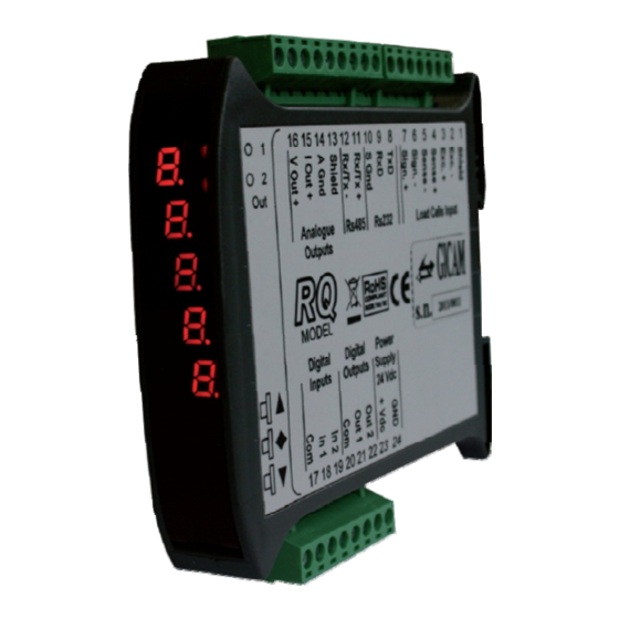
Manuale d’installazione Caratteristiche tecniche Alimentazione 24 VCC ± 10 % protetta contro l’inversione di polarità, fusibile ripristinabile Assorbimento Massimo Isolamento Classe II Categoria d’istallazione Categoria II Temperatura di stoccaggio - 20 °C / + 60 °C (- 4 °F / 140 °F) Temperatura di funzionamento - 10 °C / + 50 °C (14 °F / 122 °F), Umidità... -
Seite 10: Targa Identificativa Dello Strumento
Tutte le connessioni vanno eseguite a strumento spento. Le informazioni seguenti riguardano tutte le funzioni comprese nello strumento RQ, presenti sui vari modelli. Nel riepilogo delle connessioni si notano le funzioni presenti per ogni mo- dello. - Seite 11 Connessione delle celle di carico Eventuali connessioni di prolunga del cavo della devono essere schermate con cura, rispettando il codice colori e utilizzando il cavo del tipo fornito dal costruttore. Le con- nessioni di prolunga devono essere eseguite mediante saldatura, o attraverso morset- tiere di appoggio o tramite la cassetta di giunzione fornita a parte.
- Seite 12 Connessione ingressi logici (solo versione RQ / ANA) Gli ingressi logici sono isolati elettricamente dallo strumento mediante opto-isolatori. I cavi di connessione degli ingressi logici non devono essere incanalati con cavi di potenza o di alimentazione. Usare un cavo di connessione più corto possibile.
-
Seite 13: Connessione Uscite Analogiche
Massa segnale Connessione uscite analogiche (solo versione RQ / ANA) Lo strumento fornisce un’uscita analogica in corrente e una in tensione con le seguente caratteristiche: Uscita in tensione: range da –10 a 10 Volt oppure da –5 a 5 Volt, carico minimo 10 kΩ... - Seite 14 Connessione Ethernet (solo versione RQ / Ethernet e RQ / Ethernet IP) Normalmente i cavi sono di tipo “diretto”, e permettono la connessione a dispositivi di rete quali router o hub, ma non di connettere direttamente due PC (anche se attual-...
- Seite 15 Connessione Ethercat (solo versione RQ / Ethercat) Nella versione hardware RQ / Ethercat la connessione alla linea Ethercat viene eseguita tramite due con- nettori RJ45 non intercambiabili. Il connettore verso il panello anteriore è l’ingresso, il connettore verso il retro è l’uscita.
- Seite 16 Connessione DeviceNet (solo versione RQ / DeviceNet) Nella versione hardware RQ / DeviceNet la connessione alla linea DeviceNet viene eseguita tramite mor- settiera 5 poli estraibile con le seguente caratteristiche: DeviceNet baud rate 125, 250, 500 kbps Connettore DeviceNet...
- Seite 17 Uscita analogica 4-20 mA / 0-20 mA Uscita analogica ± 10 V / ± 5 V A seconda della versione del RQ ordinato (RS485, Analogica, Ethernet, ProfiBUS, ProfiNET, CANopen, DeviceNet) non tutte le connessioni sono disponibile. Connessioni non indicati qui sopra sono realizzate tramite connettori appositi (D-Sub ecc.).
- Seite 18 Appunti / Notes / Notizen Pagina – page – Seite...
- Seite 19 Manuale d’uso Principali caratteristiche d’uso Il RQ viene prodotto nelle seguenti versioni hardware: Firmware Versione hardware Descrizione Indicatore e trasmettitore di peso RS232 e RS485, con possibilità di collegare in rete fino a 32 strumenti in RS485, con protocolli di tra-...
-
Seite 20: Il Panello Frontale Dello Strumento
Il panello frontale dello strumento Indicatori LED Nella parte superiore del display vi sono 2 LED indicatori: LED 1: acceso = peso netto, spento = peso lordo, lampeggiante= picco LED 2: acceso = tara inserita, spento = nessuna tara presente In visualizzazione bar-graph entrambi i LED sono lampeggianti. -
Seite 21: Indicazioni A Display
I messaggi di errore riguardanti l’interfaccia fieldbus (EFbUs, N-CoN ed E-CrC) vengono visualizzati solamente in caso di versione hardware RQ / ProfiBus, RQ / ProfiNet, RQ / DeviceNET, RQ / CANopen oppure RQ / ProfiNet IP Pagina –... -
Seite 22: Ristabilire Lo Zero (Zero Semiautomatico) In Visualizzazione Peso Lordo
Visualizzazione, azzeramento peso e autotara All’accensione il display visualizza il peso netto corrente. Commutazione visualizzazione peso netto / peso lordo Premere il tasto per commutare la visualizzazione da peso netto a peso lordo e viceversa. Il valore visualizzato è segnalato dal led superiore (acceso: peso netto). - Seite 23 Torna in visualizzazione peso Programmazione soglie peso (solo versione RQ / ANA) I valori di soglia impostati vengono confrontati con 3 sec. il peso per pilotare la relativa uscita logica. Il crite-...
- Seite 24 Menu di configurazione dati di pesatura Contemporaneamente (3 secondi) Torna in visualizzazione peso Portata del sistema di pesatura Impostare il valore corrispondete alla somma delle portate nomi- nali delle celle di carico, valore espresso in kg. Questo dato co- stituisce il valore di fondo scala del sistema di pesatura.
- Seite 25 Menu di calibrazione peso Contemporaneamente (3 secondi) Torna in visualizzazione peso Taratura di zero Eseguire questa operazione a bilancia scarica (comprensiva della tara), a peso stabile. Il peso visualizzato si deve azzerare. E’ possibile ripetere più volte questa operazione. Taratura di fondo scala Prima di eseguire questa operazione, caricare sulla bilancia il peso campione e attendere la stabilizzazione, il display visualiz-...
- Seite 26 Menu di impostazione parametri di pesatura Contemporaneamente (3 secondi) Torna in visualizzazione peso Filtro peso Questo parametro permette di regolare l’azione del filtro digitale applicato sul peso rilevato. Il filtro agisce su tutte le rappresenta- zioni del dato peso. Se si programma un valore basso l’azione Imposta valore del filtro è...
- Seite 27 Torna al menu principale Inseguimento di zero La funzione di inseguimento di zero consiste nell’eseguire auto- maticamente una calibrazione di zero quando il peso subisce una lenta variazione nel tempo, l’intervento dell’inseguimento di Imposta valore zero viene determinato da questo parametro come indicato nella tabella sottostante.
- Seite 28 Sulla seriale COM2 viene gestita l’interfaccia ProfiNet RQ / DeviceNet Sulla seriale COM2 viene gestita l’interfaccia DeviceNet RQ / CANopen Sulla seriale COM2 viene gestita l’interfaccia CANopen RQ / Ethernet IP Sulla seriale COM2 viene gestita l’interfaccia Ethernet IP Contemporaneamente (3 secondi) ...
- Seite 29 MODBUS, valore impostabile Seleziona valore da 0 a 99. Questa impostazione viene utilizzata per la seriale COM2 solamente in caso di versione hardware RQ / RS485 o RQ / Ethernet. Dato di peso trasmesso COM1 / COM2 Selezione del valore trasmesso con i protocolli continuo, manua- le ed automatico (vedi relativo paragrafo).
- Seite 30 Torna al menu principale La seguente selezione è disponibile solo in caso di versione hardware RQ / RS485 o RQ / Ethernet! Le selezioni disponibili variano a seconda della versione hardware. Protocolli di comunicazione COM2 nonE: Comunicazione seriale disattivata ...
- Seite 31 7 bit (E-7-1 e O-7-1). In caso di versione Seleziona valore hardware RQ / Ethernet questo parametro definisce il formato dati della comunicazione seriale con l’interfaccia Ethernet dello strumento (vedere apposito paragrafo a pagina 44 di questo manuale).
- Seite 32 Torna al menu principale La seguente selezione è disponibile solo in caso di versione hardware RQ / ProfiNet o RQ / Ethernet IP! Subnet mask ProfiNet Programmazione della subnet mask utilizzata per il protocollo ProfiNet. I 4 byte che compongono la subnet mask devono es-...
- Seite 33 Menu gestione mappatura registri Fieldbus Il menu di gestione della mappatura dei registri bus di campo viene visualizzato solamente in caso di versione hardware RQ / ProfiBus, RQ / ProfiNet, RQ / DeviceNet, RQ / CANopen o RQ / Ethernet IP.
-
Seite 34: Menu Ingressi E Uscite Logiche
COM1. Nel programma PC “Configuratore_Prof” (PWIN75) deve es- sere selezionato il file di configurazione “CFG_PW0304_0_0_ENG.csv” fornito in dotazione. Menu ingressi e uscite logiche (solo RQ / ANA) Contemporaneamente (3 secondi) Torna in visualizzazione peso... - Seite 35 Torna al menu principale Modo di funzionamento soglia 2 Seleziona valore Selezionare in sequenza 4 criteri di funzionamento della soglia: Gross PEAk Seleziona valore Confronto con il peso netto, con il peso lordo o con il picco. In questo ultimo caso il confronto avviene con l’ultimo valore di picco acquisito, anche quando la funzione di picco non è...
- Seite 36 Menu uscita analogica (solo RQ / ANA) Contemporaneamente (3 secondi) Torna in visualizzazione peso Fondo scala E’ il peso corrispondente al fondo scala dall’uscita analogica, Imposta valore che può essere diverso dalla portata del sistema di pesatura Modo di funzionamento uscita analogica Selezione del valora da trasmettere con uscita analogica.
- Seite 37 Torna al menu principale Procedura di test uscita analogica Con questa procedura è possibile verificare il funzionamento dell’uscita analogica, determinando il valore in uscita attraverso l’uso della tastiera. Sul display viene visualizzata la percentuale del valore in uscita rispetto al fondo scala. Utilizzare i tasti per incrementare / decrementare il valo- re in uscita.
- Seite 38 Master: <Addr> “P” EOT <Addr> “P” <stato> < > <chksum> EOT picco Comando di autotara Master: <Addr> “A” EOT RQ: <Addr> “A” ACK EOT Comando di zero semiautomatico Master: <Addr> “Z” EOT RQ: <Addr> “Z” ACK EOT Pagina – page – Seite...
- Seite 39 Comando di memorizzazione soglie in memoria permanente (solo RQ / ANA) Master: <Addr> “E” EOT RQ: <Addr> “E” ACK EOT Nel caso di errore di comunicazione o comunque di comando non riuscito da RQ, esso ri- sponderà con la seguente stringa: RQ: <Addr> NAK EOT Descrizione dei campi I doppi apici (virgolette) racchiudono caratteri costanti (rispettare le maiuscole e le minuscole);...
- Seite 40 Net, CANopen o Ethernet IP) su COM1 Rs232 è sempre disponibile il protocollo MODBUS RTU, in caso di hardware RQ / Rs485 il protocollo MODBUS RTU è disponibile anche su COM2 Rs485. In caso di hard- ware RQ / Ethernet è possibile utilizzare il protocollo MODBUS TCP tramite l’interfaccia ethernet dello stru- mento, in questo caso l’interfaccia ethernet dello strumento deve essere configurata come “ModbusTCP...
- Seite 41 Picco (MSB) Valore FLOAT 40007 Picco (LSB) Valore FLOAT Solo RQ / ANA, nelle altre versioni è sempre 0. 40009 Ingressi logici Bit meno significativo = ingresso 1 Scrittura delle uscite abilitata solo se le soglie sono programmate a 0.
-
Seite 42: Holding Register
Monitor register Protocollo ProfiBus / ProfiNet / DeviceNet / CANopen / Ethernet IP Input data area (dati scritti da RQ e letti da Master, Produced Data) 128 byte La Input Data Area è personalizzabile utilizzando il programma PC “Configuratore_Prof”(PWIN75), i para-... - Seite 43 Output data area (dati scritti da RQ e letti da Master, Produced Data) 128 byte La Output Data Area è personalizzabile utilizzando il programma PC “Configuratore_Prof”(PWIN75), i para- metri selezionabili sono i seguenti (nella mappatura di default vengono utilizzati tutti):...
- Seite 44 Inserita zero stabile zero I bit 13, 12, 11 ed 10 vengono gestiti solamente in caso di versione RQ / ANA, nelle altre versioni hardware questi bit valgono sempre 0. Tabella codifica command register Funzione command register Funzione data register...
- Seite 45 0 - 20 mA 4 - 20 mA 0 - 10 V 0 - 5 V Note relative al funzionamento dell‘uscita analogica (RQ/ANA) Valori limite Quando il peso supera il fondo scala programmato l’uscita assume un valore superiore al fondo scala dell’uscita analogica fino ad un valore limite (saturazione).
- Seite 46 Configurazione interfaccia Ethernet (solo RQ / Ethernet) Non confondere con RQ / Ethernet IP. RQ / Ethernet permette di gestire i protocolli presenti su Rs232 in Ethernet. RQ / Ethernet IP consente di gestire la mappatura dei registri field- bus.
- Seite 47 Server Port: porta di comunicazione per protocollo TCP/IP, valore numerico compreso tra 1 e 65535. La connessione viene stabilita da altri dispositivi della rete (ad esempio un PC) verso RQ / Ethernet proto- collo TCP Server o protocollo ModbusTCP Server); il parametro Server Port indica la “porta TCP” sulla quale un dispositivo Client (ad esempio un PC) può...
- Seite 48 “Stato Connessione”. Per terminare una connessione TCP premere il pulsante “DISCONNETTI”. RQ / Ethernet può accettare e mantenere attiva solamente una connessione, prima di eseguire il test della connessione assicurarsi che altri dispositivi Client della rete non siano connessi con RQ/Ethernet.
-
Seite 49: Guida Alla Risoluzione Dei Problemi
Guida alla risoluzione dei problemi Problema Possibile causa Rimedio Il display visualizza il Il peso acquisito non è rilevabile perché Controllare le connessioni delle celle messagio O-L la cella è assente o collegata erronea- mente Il display visualizza il Il peso acquisito non è rappresentabile trattino alto sul display perché... - Seite 50 Pagina – page – Seite...
-
Seite 51: Technical Specification
Installation manual Technical specification Power supply 24 VCC ± 10 % protected against reverse polarity, resettable fuse Maximum absorption Insulation Class II Category of installation Category II Storage temperature - 20 °C / + 60 °C (- 4 °F / 140 °F) Operating temperature - 10 °C / + 50 °C (14 °F / 122 °F), Humidity maximum 85% non-condensing Display... -
Seite 52: Identification Plate Of The Instrument
All connections must be made with the instrument shut off . The following information pertains to all the functions included in the RQ instrument, present on the various models. In the connections summary you can see the functions present for each model. - Seite 53 Connection of the load cells Any cell cable extension connections must be carefully shielded, respecting the color code and using the cable of the type supplied by the manufacturer. The extension connections must be made by welding, or through support terminal blocks or through the junction box supplied separately.
-
Seite 54: Relay Output Connection
Logic inputs connection (only RQ / ANA version) The logic inputs are electrically isolated from the instrument by opto-isolators. The logic input connection cables must not be channeled with power or power supply cables. Use a connection cable that is as short as possible. - Seite 55 Data reception Signal mass Connection analog outputs (only RQ / ANA version) The instrument provides an analog current and a voltage output with the following characteristics: Voltage output: range from –10 to 10 Volt or from –5 to 5 Volt, minimum load 10 kΩ...
-
Seite 56: Ethernet Connection
Ethernet connection (only RQ / Ethernet and RQ / Ethernet IP versions) Normally the cables are of the "direct" type, and allow connection to network devices such as routers or hubs, but not to directly connect two PCs (even if there are current-... -
Seite 57: Profibus Connection
ProfiNet connection (only RQ / ProfiNet version) In the RQ / ProfiNet hardware version, the connection to the ProfiNet line is executed through the dedicated RJ45 connector. There are two version: with a single RJ45 connector or with two connectors. - Seite 58 DeviceNet connection (only RQ / DeviceNet version) In the RQ / DeviceNet hardware version, the connection to the DeviceNet line is made via a removable 5- pin terminal block with the following characteristics: DeviceNet baud rate 125, 250, 500 kbps...
- Seite 59 Analog output 4-20 mA / 0-20 mA Analog output ± 10 V / ± 5 V Depending on the version of the RQ ordered (RS485, Analog, Ethernet, ProfiBUS, ProfiNET, CANopen, DeviceNet) not all connections are available. Connections not indicated above are made through special connectors (D-Sub etc.).
- Seite 60 Appunti / Notes / Notizen Pagina – page – Seite...
- Seite 61 User manual Main characteristics of use The RQ is produced in the following hardware versions: Firmware Hardware version Description RS232 and RS485 weight indicator and transmitter, with the possibil- ity to network up to 32 RS485 instruments, with ASCII transmission...
-
Seite 62: Led Indicators
Short press: Switches between numeric / bar-graph display of the gross weight Long press: Reset weight / peak displayed Short press: Send data on serial line (if manual protocol selected). Long press: Programming thresholds (RQ / ANA hardware only) Pressed simultaneously: Access to the main menu Pagina –... -
Seite 63: Display Indications
Error messages concerning the fieldbus interface (EFbUs, N-CoN and E-CrC) are displayed only in the case of hardware version RQ / ProfiBus, RQ / ProfiNet, RQ / DeviceNET, RQ / CANopen or RQ / ProfiNet IP Pagina –... - Seite 64 Weight display, reset and autotare On power up, the display shows the current net weight. Switching between net weight and gross weight display Press the key to switch the display from net weight to gross weight and vice versa. The displayed value is indicated by the upper LED (lit: net weight).
-
Seite 65: Peak Function
3 sec. not maintained at shutdown. Return to weight display Weight threshold programming (only RQ / ANA version) The set threshold values are compared with the 3 sec. weight to drive the relative logic output. The com- parison criterion is established in the set-up proce-... - Seite 66 Weighing data configuration menu Simultaneously (3 seconds) Return to weight display Capacity of the weighing system Set the value corresponding to the sum of the nominal capaci- ties of the load cells, expressed in kg. This value constitutes the full scale value of the weighing system.
- Seite 67 Weight calibration menu Simultaneously (3 seconds) Return to weight display Zero calibration Carry out this operation with the scale unloaded (including the tare), with a stable weight. The displayed weight must be reset. It is possible to repeat this operation several times. Full scale calibration Before carrying out this operation, load the sample weight on the scale and wait for stabilization, the display shows the measured...
- Seite 68 Weighing parameters setting menu Simultaneously (3 seconds) Return to weight display Weight filter This parameter allows you to adjust the action of the digital filter applied on the detected weight. The filter acts on all the repre- sentations of the given weight. If you program a low value, the Set value filter action is lower while programming a high value the weight is more filtered .
- Seite 69 Return to main menu Zero tracking The zero tracking function consists of automatically performing a zero calibration when the weight undergoes a slow variation over time, the zero tracking intervention is determined by this Set value parameter as indicated in the table below. To disable the func- tion, set the value 0.
- Seite 70 RQ / DeviceNet The DeviceNet interface is managed on the COM2 serial RQ / CANopen The CANopen interface is managed on the COM2 serial RQ / Ethernet IP The Ethernet IP interface is managed on the COM2 serial Simultaneously (3 seconds) ...
- Seite 71 Set value the transmission. This selection is used for the COM2 serial only in the case of hardware version RQ / RS485 or RQ / Ethernet. Pagina – page –...
- Seite 72 Return to main menu The following selection is only available in the case of hardware version RQ / RS485 or RQ / Ethernet! The selections available vary depending on the hardware version. Protocolli di comunicazione COM2 nonE: Serial communication deactivated ...
- Seite 73 Selectable values: N-8-1, N-8-2, E-8-2, O-8-1, E-7-1, O-7-1. In case of SLAVE or MODBUS protocol it is not possible to se- lect 7 bit data format (E-7-1 and O-7-1). In case of RQ / Ethernet Select value hardware version this parameter defines the data format of the serial communication with the instrument's Ethernet interface (see the specific paragraph on page 87 of this manual).
- Seite 74 Return to main menu The following selection is only available in case of hardware version RQ / ProfiNet or RQ / Ethernet IP! ProfiNet subnet mask Programming of the subnet mask used for the ProfiNet protocol. The 4 bytes that make up the subnet mask must be pro-...
- Seite 75 Fieldbus register mapping management menu The fieldbus register management management menu is only displayed in the case of hard- ware version RQ / ProfiBus, RQ / ProfiNet, RQ / DeviceNet, RQ / CANopen or RQ / Ethernet Simultaneously (3 seconds) ...
- Seite 76 COM1. In the PC program "Configuratore_Prof" (PWIN75) the con- figuration file "CFG_PW0304_0_0_ENG.csv" must be select- Logic inputs and outputs menu (only RQ / ANA version) Simultaneously (3 seconds) Return to weight display...
- Seite 77 Return to main menu Threshold 2 operating mode Select value Select 4 threshold operating criteria in sequence: Gross PEAk Select value Comparison with the net weight, with the gross weight or with the peak. In the latter case, the comparison takes place with the last peak value acquired, even when the peak function inactive.
- Seite 78 Analog output menu (only RQ / ANA version) Simultaneously (3 seconds) Return to weight display Full scale The weight corresponding to the full scale of the analog output, Set value which can be different from the nominal capacity of the system.
- Seite 79 Return to main menu Analog output test procedure With this procedure it is possible to check the operation of the analog output, determining the output value through the use of the keyboard. The display shows the percentage of the output value with re- spect to the full scale.
- Seite 80 Master: <Addr> “P” EOT <Addr> “P” <state> < > <chksum> EOT peak Autotare command Master: <Addr> “A” EOT RQ: <Addr> “A” ACK EOT Semi-automatic zero command Master: <Addr> “Z” EOT RQ: <Addr> “Z” ACK EOT Pagina – page – Seite...
- Seite 81 Command to store thresholds in permanent memory (only RQ / ANA) Master: <Addr> “E” EOT RQ: <Addr> “E” ACK EOT In case of communication error or in any case of command failed from RQ, it will respond with the following string: RQ: <Addr> NAK EOT...
- Seite 82 CANopen or Ethernet IP) the MODBUS RTU protocol is always available on COM1 Rs232, in the case of RQ / Rs485 hardware the MODBUS RTU protocol is also available on COM2 Rs485. In the case of RQ / Ethernet hardware, the MODBUS TCP protocol can be used via the instrument's Ethernet interface, in this case the instrument's ethernet interface must be configured as "ModbusTCP Server"...
- Seite 83 FLOAT value 40007 Peak (LSB) FLOAT value Only RQ / ANA, in the other versions it is always 0. 40009 Logic inputs Least significant bit = input 1 Writing of the outputs enabled only if the thresholds are programmed to 0.
-
Seite 84: Holding Register
ProfiBus / ProfiNet / DeviceNet / CANopen / Ethernet IP protocol Input data area (data written by RQ and read by Master, Produced Data) 128 bytes The Input Data Area can be customized using the PC program "Configuratore_Prof" (PWIN75), the se-... - Seite 85 The data of the input data area is updated at a frequency of 25 Hz. To transfer the parameters of the Output Data Area to the RQ instrument, direct access to the memory must be enabled, writing the value 0x7FFF in the Command Register (address 40503).
- Seite 86 Band stable center Bits 13, 12, 11 and 10 are only managed in the case of the RQ / ANA version, in the other hardware versions these bits are always worth 0. Command register coding table Command register function...
-
Seite 87: Limit Values
4 - 20 mA 0 - 10 V 0 - 5 V Notes on the operation of the analogue output (only RQ/ANA) Limit values When the weight exceeds the programmed full scale, the output assumes a value higher than the full scale of the analog output up to a limit value (saturation). - Seite 88 Ethernet interface configuration (RQ/Ethernet only) Do not confuse with RQ / Ethernet IP. RQ / Ethernet allows to manage the protocols pre- sent on Rs232 in Ethernet. RQ / Ethernet IP allows you to manage the mapping of fieldbus registers.
-
Seite 89: Parameter Configuration
Server Port: communication port for TCP / IP protocol, numerical value between 1 and 65535. The con- nection is established by other devices on the network (for example a PC) to RQ / Ethernet TCP Server protocol or ModbusTCP Server protocol); the Server Port parameter indicates the "TCP port" on which a Client device (for example a PC) can make a TCP connection with RQ / Ethernet. - Seite 90 "Connection Status" section. To end a TCP connection, press the "DISCONNECT" button. RQ / Ethernet can only accept and keep one connection active, before testing the connection make sure that other Client devices on the network are not connected with RQ / Ethernet.
-
Seite 91: Troubleshooting Guide
Troubleshooting guide Problem Possible cause Remedy The display shows the The acquired weight is not detectable Check the connection of the load cell message O-L because the cell is absent or connected incorrectly The display shows the The acquired weight cannot be repre- high dash on the upper sented because it exceeds the five display... - Seite 92 Pagina – page – Seite...
-
Seite 93: Technische Eigenschaften
Installationsanleitung Technische Eigenschaften Stromversorgung 24 VDC ± 10% gegen Verpolung geschützt, rücksetzbare Sicherung Maximale Stromaufnahme Isolierung Klasse II Installationskategorie Kategorie II Lagertemperatur - 20 °C / + 60 °C (- 4 °F / 140 °F) Betriebstemperatur - 10 °C / + 50 °C (14 °F / 122 °F), Luftfeuchtigkeit maximal 85% Display Numerisch mit 5 roten LED Anzeigen mit je 7 Segmenten (h 7 mm) 2 LED mit 3 mm (Funktionsstatus) -
Seite 94: Typenschild Des Gerätes
Alle Anschlüsse müssen bei ausgeschaltetem Gerät durchgeführt werden. Die nachfolgenden Informationen beziehen sich auf alle Funktionen des RQ-Verstärkers, die in den verschiedenen Modellen vorhanden sind. In der Anschlussübersicht sehen Sie die Funktionen die in den einzelnen Modellen vorhanden sind. -
Seite 95: Anschluss Der Wägezellen
Anschluss der Wägezellen Alle Verlängerungsanschlüsse des Kabels müssen unter Berücksichtigung des Farbcodes und unter Verwendung des vom Hersteller gelieferten Kabels sorgfältig abgeschirmt werden. Die Verlängerungsverbindungen müssen durch Löten, durch Klemmenblöcke oder mit der separat mitgelieferte Anschlussdose hergestellt werden. Das Kabel der Zelle darf nicht mit anderen Kabeln (z. -
Seite 96: Anschluss Logische Eingänge
Anschluss logische Eingänge (nur Version RQ / ANA) Die Logikeingänge sind durch Optokoppler vom Instrument elektrisch isoliert. Die Verbindungskabel der logischen Eingänge dürfen nicht zusammen mit Leistungs- kabeln oder Stromversorgungskabeln verlegt werden. Verwenden Sie ein möglichst kurzes Anschlusskabel Um einen logischen Eingang zu aktivieren, muss auf an den Pluspol einer 24 Volt Gleichstromversorgung gelegt werden, während die Masse an deren Minuspol angeschlossen werden muss. -
Seite 97: Serieller Rs232 Anschluss
Datenempfang Masse Signal Anschluss logische Ausgänge (nur Version RQ / ANA) Das Gerät bietet je einen analogen Strom– und Spannungsausgang mit den folgenden Eigenschaften: Spannungsausgang: Bereich von -10 bis +10 Volt oder von -5 bis +5 Volt, Mindestlast 10 kΩ... -
Seite 98: Ethernet-Anschluss
Ethernet Anschluss (nur Versionen RQ / Ethernet und RQ / Ethernet IP) Normalerweise sind die Kabel vom Typ "direkt" und ermöglichen den Anschluss an Netzwerkgeräte wie Router oder Hubs, jedoch nicht den direkten Anschluss von zwei PCs (selbst wenn derzeit Netzwerkkarten mit Auto-Sensing-Technologie vorhanden sind, die den Kabel-Typ und die Art der Verbindung erkennen, die direkte PC-PC- Verbindungen auch mit nicht überkreuzten Kabeln ermöglichen). -
Seite 99: Profibus Verbindung
ProfiNet Verbindung (nur Version RQ / ProfiNet) In der Hardware-Version RQ/ProfiNet erfolgt die Verbindung an die ProfiNet Leitung über einen speziellen RJ45-Anschluss. Es gibt 2 Versionen: mit nur einem RJ45-Anschluss oder mit zwei RJ45-Anschlüssen. Bei zwei Anschlüssen ist der Eingang und der Ausgang der ProfiNet-Leitung gleichgültig. -
Seite 100: Devicenet Verbindung
DeviceNet Verbindung (nur Version RQ / DeviceNet) In der RQ / DeviceNet-Hardwareversion erfolgt die Verbindung zur DeviceNet-Leitung über einen abnehm- baren 5-poligen Klemmenblock mit folgenden Eigenschaften: DeviceNet baud rate 125, 250, 500 kbps 5 poliger DeviceNet Anschluss CAN_L Schirm... -
Seite 101: Anschlussübersicht
Analogausgang 4-20 mA / 0-20 mA Analogausgang ± 10 V / ± 5 V Abhängig von der bestellten Version des RQ (RS485, Analog, Ethernet, ProfiBUS, ProfiNET, CANopen, DeviceNet) sind nicht alle Verbindungen verfügbar. Die oben nicht angegebenen Verbindungen erfolgen über spezielle Anschlüsse (D-Sub usw.). - Seite 102 Appunti / Notes / Notizen Pagina – page – Seite...
- Seite 103 Bedienungsanleitung Hauptmerkmale der Verwendung Der RQ wird in den folgenden Hardwareversionen hergestellt: Firmware Hardware Version Beschreibung Gewichtsanzeige und Sender RS232 und RS485 mit der Möglichkeit, bis zu 32 Instrumente in RS485 zu vernetzen, mit ASCII- RQ / RS485 Übertragungsprotokollen für die kontinuierliche Übertragung, auf An- frage oder über manuelle Steuerung und MODBUS RTU-Protokoll.
-
Seite 104: Die Frontplatte Des Gerätes
Kurzes Drücken: Schaltet die numerische / Balkendiagrammanzeige des Bruttogewichts um Langes Drücken: angezeigtes Gewicht / Spitzenwert zurücksetzen Kurz drücken: Daten auf serieller Leitung senden (falls manuelles Protokoll ausgewählt). Langes Drücken: Programmierung Schwellenwerte (nur RQ / Ana-Hardware) Gleichzeitig gedrückt: Zugriff auf das Hauptmenü Pagina –... -
Seite 105: Anzeigen Auf Dem Display
Kalib- rierung abzubrechen. Fehlermeldungen bezüglich der Feldbusschnittstelle (EFbUs, N-CoN und E-CrC) werden nur bei der Hardwareversion RQ / ProfiBus, RQ / ProfiNet, RQ / DeviceNET, RQ / CANopen oder RQ / ProfiNet IP angezeigt Pagina – page –... -
Seite 106: Anzeige Und Rücksetzen Des Gewichts Sowie Autotara
Anzeige und Rücksetzen des Gewichts sowie Autotara Beim Einschalten zeigt das Display das aktuelle Nettogewicht an. Umschalten zwischen Netto– und Bruttogewichtsanzeige Drücken Sie die Taste um die Anzeige vom Netto- zum Bruttogewicht und umgekehrt umzuschalten. Der angezeigte Wert wird durch die obere LED angezeigt (an: Nettogewicht). -
Seite 107: Programmierung Gewichtsschwellenwerte
LED. Der berechnete Spitzenwert 3 Sek. wird beim Ausschalten nicht beibehalten. Zurück zur Gewichtsanzeige Programmierung Gewichtsschwellenwerte (nur Version RQ / ANA) Die eingestellten Schwellenwerte werden mit dem 3 Sek. Gewicht verglichen, um den relativen Logikaus- gang anzusteuern. Das Vergleichskriterium wird... - Seite 108 Wiegedaten Konfigurationsmenü Gleichzeitig (3 Sekunden) Zurück zur Gewichtsanzeige Nennlast des Wägesystems Stellen Sie den Wert ein, der der Summe der Nennlasten der Wägezellen, ausgedrückt in kg, entspricht ein. Dieser Wert stellt den Skalenendwert des Wägesystems dar. Werte zwischen 1 Wert einstellen und 9999 werden akzeptiert.
-
Seite 109: Menü Zur Gewichtskalibrierung
Menü zur Gewichtskalibrierung Gleichzeitig (3 Sekunden) Zurück zur Gewichtsanzeige Nullkalibrierung Führen Sie diesen Vorgang bei unbelasteter Waage (einschließlich Tara) und stabilisiertem Gewicht durch. Das an- gezeigte Gewicht muß zurückgesetzt werden. Der Vorgang kann mehrmals wiederholt werden. Kalibrierung Skalenendwert Bevor Sie diesen Vorgang ausführen, laden Sie das Probenge- wicht auf die Waage und warten Sie auf die Stabilisierung. -
Seite 110: Menü Zum Einstellen Der Wiegeparameter
Menü zum Einstellen der Wiegeparameter Gleichzeitig (3 Sekunden) Zurück zur Gewichtsanzeige Gewichtsfilter Mit diesem Parameter können Sie die Wirkung des Digitalfilters auf das erkannte Gewicht einstellen. Der Filter wirkt auf alle Dar- stellungen des angegebenen Gewichts. Wenn Sie einen niedri- Wert einstellen gen Wert programmieren, ist die Filteraktion geringer, während bei einem hohen Wert das Gewicht stärker gefiltert wird. - Seite 111 Zurück zum Hauptmenü Nullpunktverfolgung Die Nullpunktverfolgungsfunktion besteht darin, automatisch eine Nullkalibrierung durchzuführen, wenn sich das Gewicht im Laufe der Zeit langsam ändert. Die Nullpunktverfolgung wird Wert einstellen durch diesen Parameter bestimmt, wie in der folgenden Tabelle angegeben. Um die Funktion zu deaktivieren, stellen Sie den Wert 0 ein.
-
Seite 112: Einrichtungsmenü Für Serielle Kommunikationsanschlüsse
Die ProfiNet-Schnittstelle wird auf der seriellen COM2-Schnittstelle verwaltet RQ / DeviceNet Die DeviceNet-Schnittstelle wird auf der seriellen COM2-Schnittstelle verwaltet RQ / CANopen Die CANopen-Schnittstelle wird auf der seriellen COM2-Schnittstelle verwaltet RQ / Ethernet IP Die Ethernet IP-Schnittstelle wird auf der seriellen COM2-Schnittstelle verwaltet Gleichzeitig (3 Sekunden) ... - Seite 113 Instrument die Antwort auf die Anforderung des Masters sendet, wenn dieser am Ende der Übertragung nicht Wert einstellen sofort empfangen kann. Diese Auswahl wird für die COM2- Schnittstelle nur bei der Hardwareversion RQ / RS485 oder RQ / Ethernet verwendet. Pagina – page –...
- Seite 114 Zurück zum Hauptmenü Die folgende Auswahl ist nur bei Hardwareversion RQ / RS485 oder RQ / Ethernet verfüg- bar! Die verfügbaren Auswahlmöglichkeiten variieren je nach Hardwareversion. Kommunikationsprotokolle COM2 Serielle Kommunikation deaktiviert nonE: Contn: Kontinuierliche Übertragung des Gewichtsstring. Kann z. B. verwendet werden, um eine Gewichtsan- Wert auswählen...
- Seite 115 Programmierung der für die Protokolle ProfiBus, DeviceNet und Wert einstellen CANopen verwendeten Adresse (von 0 bis 126). Die folgende Auswahl ist nur bei Hardwareversion RQ / ProfiNet oder RQ / Ethernet IP ver- fügbar! IP Adresse Programmierung der für ProfiNet-Protokolle verwendeten Adres- se.
- Seite 116 Zurück zum Hauptmenü Die folgende Auswahl ist nur bei Hardwareversion RQ / ProfiNet oder RQ / Ethernet IP ver- fügbar! Subnet mask ProfiNet Programmierung der für das ProfiNet-Protokoll verwendeten Subnetzmaske. Die 4 Bytes, aus denen die Subnetzmaske be- Wert einstellen steht, müssen nacheinander programmiert werden (wie auf der...
-
Seite 117: Menü Zur Verwaltung Der Feldbusregisterzuordnung
Menü zur Verwaltung der Feldbusregisterzuordnung Das Verwaltungsmenü zur Verwaltung des Feldbusregisters wird nur bei der Hardwareversi- on RQ / ProfiBus, RQ / ProfiNet, RQ / DeviceNet, RQ / CANopen oder RQ / Ethernet IP an- gezeigt. Gleichzeitig (3 Sekunden) ... -
Seite 118: Menü Logische Ein- Und Ausgänge
Datenformat müssen den für COM1 programmierten Ein- stellungen entsprechen. Im PC-Programm "Configuratore_Prof" (PWIN75) muss die Konfigurationsdatei "CFG_PW0304_0_0_ENG.csv" ausge- wählt werden. Menü logische Ein- und Ausgänge (nur RQ / ANA) Gleichzeitig (3 Sekunden) Zurück zur Gewichtsanzeige Betriebsart Schwellenwert 1 Wert auswählen... - Seite 119 Zurück zum Hauptmenü Betriebsart Schwellenwert 2 Wert auswählen Wählen Sie nacheinander 4 Schwellenwert-Kriterien aus: Gross PEAk Wert auswählen Vergleich mit Nettogewicht, Bruttogewicht oder Spitzenwert. Im letzten Fall erfolgt der Abgleicht mit dem letzten erfassten Spit- zenwert auch wenn die Spitzenwertfunktion deaktiviert ist. Wert auswählen n.o.
- Seite 120 Menü Analogausgang (nur RQ / ANA) Gleichzeitig (3 Sekunden) Zurück zur Gewichtsanzeige Skalenendwert Das Gewicht, dass dem Skalenendwert des Analogausganges Wert einstellen entspricht und sich vom Skalenendwert des Wägesystems un- terscheiden kann. Betriebsart Analogausgang Auswahl des vom Analogausgang übertragenen Wertes.
-
Seite 121: Kontinuierliches, Automatisches Und Manuelles Übertragungsprotokoll
Zurück zum Hauptmenü Testverfahren für den Analogausgang Mit diesem Verfahren ist es möglich, die Funktion des Analog- ausgangs zu überprüfen und den Ausgabewert mit Hilfe der Tastatur zu bestimmen. Das Display zeigt den Prozentsatz des Ausgabewerts in Bezug auf den Skalenendwert an. Verwenden Sie die Tasten um den Ausgabewert zu erhöhen / zu verringern. -
Seite 122: Slave Übertragungsprotokoll
Anforderung aktueller Spitzenwert Master: <Addr> “P” EOT <Addr> “P” <stato> < > <chksum> EOT picco Autotara-Befehl Master: <Addr> “A” EOT RQ: <Addr> “A” ACK EOT Halbautomatischer Nullbefehl Master: <Addr> “Z” EOT RQ: <Addr> “Z” ACK EOT Pagina – page – Seite... - Seite 123 RQ: <Addr> “R” <set1> < > ETX <chksum> EOT set2 Befehl zur Aktivierung der Logikausgänge (nur RQ / ANA, wenn die Schwellenwerte 0 programmiert sind) Master: <Addr> “U” <Ausgänge> EOT RQ: <Addr> “U” ACK EOT Anforderung Zustand Logikeingänge (nur RQ / ANA) Master: <Addr>...
-
Seite 124: Fehlerbehandlung Von Kommunikationsfehlern
Für jede Hardwarekonfiguration des Instruments (Rs485, Ana, Ethernet, Profibus, Profinet, DeviceNet, CANopen oder Ethernet IP) ist das MODBUS RTU-Protokoll immer auf COM1 Rs232 verfügbar, bei RQ / Rs485-Hardware ist das MODBUS RTU-Protokoll ebenfalls auf COM2 Rs485 verfügbar . Bei RQ / Ethernet -Hardware kann das MODBUS-TCP-Protokoll über die Ethernet-Schnittstelle des Instruments verwendet... -
Seite 125: Fehlerbehandlung Der Empfangenen Daten
FLOAT-Wert 40006 Spitzenwert (MSB) FLOAT-Wert 40007 Spitzenwert (LSB) FLOAT-Wert Nur RQ / ANA, in den anderen Versionen immer 0. 40009 Logische Eingänge Kleinstwertiges Bit = Eingang 1 Nur RQ / ANA, in den anderen Versionen immer 0. 40010 Logische Ausgänge... - Seite 126 Monitor register ProfiBus / ProfiNet / DeviceNet / CANopen / Ethernet IP Protokoll Input data area (Daten von RQ geschrieben und vom Master gelesen, Produced Data) 128 Bytes Der Eingabedatenbereich kann mit dem PC-Programm "Configuratore_Prof" (PWIN75) angepasst werden. Folgende Parameter können ausgewählt werden (in der Standardzuordnung werden alle verwendet):...
- Seite 127 Output data area (Daten von RQ geschrieben und vom Master gelesen, Produced Data ) 128 byte Der Ausgabedatenbereich kann mit dem PC-Programm "Configuratore_Prof" (PWIN75) angepasst werden. Folgende Parameter können ausgewählt werden (in der Standardzuordnung werden alle verwendet): Register Adresse Holding register...
- Seite 128 Nullband fehler Eingestellt Stabil Zentrum Die Bits 13, 12, 11 und 10 werden nur bei der RQ / ANA-Version verwaltet, bei den anderen Hardwareversionen haben diese Bits immer den Wert 0. Kodierungstabelle command register Funktion command register Funktion data register...
- Seite 129 0 - 20 mA 4 - 20 mA 0 - 10 V 0 - 5 V Hinweise zur Funktionsweise des Analogausgangs (RQ / ANA) Grenzwerte Wenn das Gewicht den programmierten Skalenendwert überschreitet, nimmt der Ausgang einen Wert an, der bis zu einem Grenzwert (Sättigung) höher als der Skalenendwert des Analogausgangs ist.
-
Seite 130: Konfiguration Der Ethernet-Schnittstelle
Konfiguration der Ethernet-Schnittstelle (nur RQ / ETHERNET) Nicht mit RQ / Ethernet IP verwechseln. Mit RQ / Ethernet können die auf Rs232 im Ether- net vorhandenen Protokolle verwaltet werden. Mit RQ / Ethernet IP können Sie die Zuord- nung von Feldbusregistern verwalten. -
Seite 131: Parameterkonfiguration
Die Verbindung wird von anderen Geräten im Netzwerk (z. B. einem PC) zum RQ / Ethernet-TCP- Server-Protokoll oder zum ModbusTCP-Server-Protokoll hergestellt. Der Parameter Server Port gibt den "TCP-Port" an, an dem ein Client (z. B. ein PC) eine TCP-Verbindung mit RQ / Ethernet herstellen kann. ... - Seite 132 Abschnitt "Verbindungsstatus" angezeigt. Um eine TCP-Verbindung zu beenden, klicken Sie auf die Schaltfläche "DISCONNECT". RQ / Ethernet kann nur eine Verbindung akzeptieren und aufrechterhalten. Stellen Sie vor dem Testen der Verbindung sicher, dass andere Client-Geräte im Netzwerk nicht mit RQ / Ethernet verbunden sind.
-
Seite 133: Anleitung Zur Fehlerbehebung
Anleitung zur Fehlerbehebung Problem Mögliche Ursache Lösung Das Display zeigt die Das erfasste Gewicht ist nicht erkenn- Überprüfen Sie den Anschluss der Wä- Meldung O-L an bar, da die Zelle fehlt oder falsch ver- gezelle bunden ist Das Display zeigt den Das erfasste Gewicht kann nicht darge- hohen Strich im oberen stellt werden, da es die fünf verfügbaren... - Seite 134 Pagina – page – Seite...
- Seite 135 Questo manuale è stato redatto con la massima cura ed al momento della pubblicazione è ritenuto privo di errori. GICAM si impegna di mantenere questo manuale sempre aggiornato e pubblicare versioni aggiornati sul suo sito web appena disponibile. Si declina ogni responsabilità per danni causati da errori in questo momento non identificati e si chiede di segnalare eventuali errori o incongruenze usando i nostri contatti indicati sul retro di questa copertina.