Inhaltsverzeichnis
Werbung
Verfügbare Sprachen
Verfügbare Sprachen
Quicklinks
Werbung
Inhaltsverzeichnis

Verwandte Anleitungen für Gicam RQA


Inhaltszusammenfassung für Gicam RQA
- Seite 1 Manuale Manual Handbuch...
- Seite 2 Manuale d’istallazione e d’uso Installation and user manual Installations- und Bedienungsanleitung AMPLIFICATORE digitale/analogico per celle di carico Digital / Analog load cell AMPLIFIER Digital / Analog-VERSTÄRKER für Wägezellen...
-
Seite 3: Inhaltsverzeichnis
Sommario / Table of contents / Inhaltsverzeichnis Sommario / Table of contents / Inhaltsverzeichnis ..............1 Manuale d’installazione ........................ 3 Caratteristiche tecniche..........................3 Simbologia ..............................4 Avvertenze ..............................4 Targa identificativa dello strumento ....................... 4 Alimentazione dello strumento ........................5 Connessione delle celle di carico ........................ - Seite 4 Installationsanleitung ......................... 15 Technische Spezifikation ..........................15 Symbole ............................... 16 Warnungen ..............................16 Typenschild des Gerätes ..........................16 Stromversorgung des Instruments ....................... 17 Anbindung der Wägezellen .......................... 17 Anschluss der analogen Ausgänge ......................18 Eigenschaften ............................18 Anbindungen analoge Ausgänge ......................... 18 Bedienungsanleitung........................
-
Seite 5: Manuale D'installazione
Manuale d’installazione Caratteristiche tecniche Alimentazione 24 V dc ± 10 % protetta contro l’inversione di polarità. Protezione con fusibile ripristinabile Assorbimento massimo 1 Watt Isolamento Classe II Categoria d’installazione Categoria II Temperatura di stoccaggio - 20 °C / + 60 °C Temperatura di funzionamento - 10 °C / + 50 °C Umidità... -
Seite 6: Simbologia
Simbologia Di seguito vengono riportate le simbologie utilizzate nel manuale per richiamare l’attenzione del lettore: Attenzione! Questa operazione deve essere eseguita da personale specializzato. Prestare particolare attenzione alle indicazioni seguenti. Ulteriori informazioni Avvertenze Le procedure di seguito riportate, devono essere eseguite da personale specializzato. ... -
Seite 7: Alimentazione Dello Strumento
Alimentazione dello strumento Lo strumento viene alimentato attraverso i morsetti 11 e 12. Il cavo di alimentazione deve essere incanalato separatamente da altri cavi di alimentazioni con tensioni diverse, dai cavi delle celle di carico e degli ingressi/uscite logici. Il circuito interno è... -
Seite 8: Connessione Uscite Analogiche
Connessione uscite analogiche Lo strumento fornisce un’uscita analogica in corrente ed una in tensione. Caratteristiche Uscita analogica in tensione: campo da -10 a +10 Volt oppure da -5 a +5 Volt, carico minimo 10 kΩ Uscita analogica in corrente: campo da 0 a 20 mA oppure da 4 a 20 mA. Il carico massimo è 300Ω ... -
Seite 9: Manuale D'uso
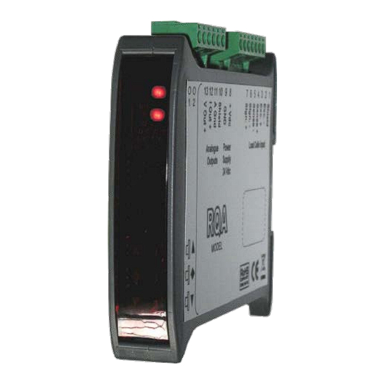
Manuale d’uso Principali caratteristiche d’uso Le caratteristiche principali di funzionamento sono la gestione di un’uscita analogica; l’uscita può essere sia in Volt che in mA. Il panello frontale dello strumento Indicatori LED Lo strumento è provvisto di due indicatori LED: LED1 LED2 Stato dello strumento... -
Seite 10: Funzioni Operative
Funzioni operative Impostazione filtro digitale Premere il tasto per 3 secondi per accedere all’impostazione del filtro digitale. ▲ incrementa filtro Conferma e torna al normale funzionamento ▼ Decrementa filtro ●● Quando si è all’interno della funzione di impostazione filtro i LED sono entrambi accesi Premere il tasto ▲... -
Seite 11: Installation Manual
Installation manual Technical specification Power supply 24 V direct current ± 10 % protected against inversion of polarity. Protection resettable fuse Maximum power consumption 1 Watt Insulation Class II Installation category Category II Operating temperature 14 °F / 122 °F Humidity maximum 85% non-condensing 2 LED with 3 mm (function status) -
Seite 12: Symbology
Symbology Attention! This operation has to be carried out by specialized personnel. Pay particular attention to the following indications! Further information Warnings The procedures listed below have to be executed by specialized operators! All connections have to be executed with the instrument shut off! Identification plate of the instrument ... -
Seite 13: Power Supply Of The Instrument
Power supply of the instrument The instrument is powered through the terminals number 11 and 12 The power supply cable must be routed separately from other power supply cables with dif- ferent voltages, load cell cables and logic inputs/outputs. The internal circuit is galvanically isolated from the supply voltage. -
Seite 14: Connection Of Analog Outputs
Connection of analog outputs The instrument supplies an analog output in current and one in tension. Characteristics Analog output in tension: range from -10 to +10 Volt or from -5 to +5 Volt, minimum load 10 kΩ Analog output in current: range from 0 to 20 mA or from 4 to 20 mA. The maximum load is 300Ω. ... -
Seite 15: User Manual
User manual Main characteristics of use The main operating features are the management of an analog output, the output can be in Volt or in mA. Front panel of the instrument LED indicators The instrument is equipped with two LED indicators LED1 LED2 Status of the instrument... -
Seite 16: Operational Functions
Operational functions Digital filter setting Press the key for 3 seconds to access the digital filter settings. ▲ Increase filter Confirm and return to normal functioning ▼ Decrease filter ● ● When you are inside the filter setting function, the LEDs are both lit Pressing the key ▲... -
Seite 17: Installationsanleitung
Installationsanleitung Technische Spezifikation Stromversorgung 24 V Gleichstrom ± 10 % gegen Polaritätsumkehr geschützt. Schutz durch Sicherung Maximale Stromaufnahme 1 Watt Isolierung Klasse II Installationskategorie Kategorie II Lagertemperatur - 20 °C / + 60 °C Betriebstemperatur - 10 °C / + 50 °C Luftfeuchtigkeit Maximal 85% nicht kondensierend 2 LED mit 3 mm (Funktionsstatus) -
Seite 18: Symbole
Symbole Die nachfolgenden Symbole werden in diesem Handbuch verwendet um die Aufmerksamkeit des Lesers auf wichtige Punkte zu lenken: Achtung! Dieser Vorgang muss von Fachpersonal ausgeführt werden! Beachten Sie besonders die folgenden Hinweise! Weitergehende Informationen Warnungen Die unten aufgeführten Operationen müssen von Fachpersonal ausgeführt werden! ... -
Seite 19: Stromversorgung Des Instruments
Stromversorgung des Instruments Das Gerät wird über die Klemmen 11 und 12 mit Strom versorgt. Das Stromversorgungskabel muss getrennt von anderen Stromkabeln mit unterschiedli- chen Spannungen, Kabeln von Wäge-zellen und Logikein- / ausgängen verlegt werden Der interne Stromkreis ist galvanisch von der Versorgungsspannung getrennt. Versorgungsspannung: 24 Volt Gleichstrom, ±... -
Seite 20: Anschluss Der Analogen Ausgänge
Anschluss der analogen Ausgänge Das Gerät stellt einen analogen Ausgang in Spannung und einen Ausgang in Strom zur Verfügung. Eigenschaften Analogausgang in Spannung: Bereich von -10 bis +10 V oder von -5 bis +5 V, Minimallast 10 kΩ Analogausgang in Strom: Bereich von 0 bis 20 mA oder von 4 bis 20 mA. Maximallast 300Ω. ... -
Seite 21: Bedienungsanleitung
Bedienungsanleitung Hauptmerkmale der Benutzung Die wichtigste Betriebsfunktion ist die Verwaltung eines Analogausganges. Die Ausgabe kann entweder in Volt oder in mA erfolgen Die Frontplatte des Instrumentes LED Anzeigen Das Gerät ist mit zwei Anzeige-LED ausgestattet: LED1 LED2 Gerätestatus Normalbetrieb Blinkend Nullpunktkorrekturfunktion des Analogausgangs in Ausführung Blinkend Span offset Korrekturfunktion Analogausgang in Ausführung... -
Seite 22: Betriebsfunktionen
Betriebsfunktionen Einstellung Digitalfilter Drücken Sie die Taste für 3 Sekunden um zu den Einstellungen des Digitalfilters zu gelangen. ▲ Filter erhöhen Bestätigung und zurück zum Normalbetrieb ▼ Filter verringern ● ● Wenn Sie sich in der Filtereinstellungsfunktion befinden, leuchten beide LEDs Durch Drücken der Taste ▲... - Seite 23 La versione più aggiornato di questo materiale è disponibile sul nostro sito: www.gricamgra.com The latest version of this manual can be downloaded from our website: www.gicamloadcells.com Die neueste Version dieses Handbuches finden Sie auf: www.gicamwaegesystemwiegezellen.com...