
Verwandte Anleitungen für DFI Lanparty Blood-Iron P45 Elite Serie


Inhaltszusammenfassung für DFI Lanparty Blood-Iron P45 Elite Serie
- Seite 1 System Board User’s Manual 935-BP45E1-000G 10200915E Downloaded from www.Manualslib.com manuals search engine...
-
Seite 2: Trademarks
Copyright This publication contains information that is protected by copyright. No part of it may be reproduced in any form or by any means or used to make any transfor- mation/adaptation without the prior written permission from the copyright hold- ers. -
Seite 3: Inhaltsverzeichnis
Table of Contents About this Manual................Warranty....................Static Electricity Precaution..............Safety Measures..................About the Package................Before Using the System Board............System Board Layout................English..................... Français....................Deutsch....................Italiano....................Español....................Debug LED POST and Troubleshooting.......... Downloaded from www.Manualslib.com manuals search engine... -
Seite 4: About This Manual
Utility CD) will appear. Click the “TOOLS” icon then click “Manual” on the main menu. For additional information on the system board, please download the complete version of the manual from DFI’s website. Visit www.dfi.com. Warranty 1. Warranty does not cover damages or failures that arised from misuse of the product, inability to use the product, unauthorized replacement or alteration of components and product specifications. -
Seite 5: Static Electricity Precaution
English Static Electricity Precautions It is quite easy to inadvertently damage your PC, system board, components or devices even before installing them in your system unit. Static electrical dis- charge can damage computer components without causing any signs of physical damage. -
Seite 6: About The Package
Genie BIOS allows configuring the system to optimize system performance and overclock capability. For detailed information about Genie BIOS, please download the Genie BIOS Guideline from DFI’s website (www.dfi.com). The guideline is also available in the provided DVD. Before Using the System Board Before using the system board, prepare basic system components. -
Seite 7: System Board Layout
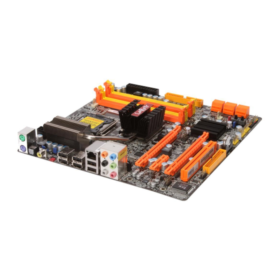
English System Board Layout PS/2 power select (JP7) Mouse CPU fan DDR2-2 Optical DDR2-4 DDR2-3 S/PDIF-out DDR2-1 Coaxial RCA C217 S/PDIF-out Clear CMOS (JP8) USB 9 USB 8 power USB 6-11 power select (JP5) USB 11 USB 10 USB 7 USB 6 Intel Center/... -
Seite 8: English
English Chapter 1 - Introduction Specifications Processor • LGA 775 socket for: - Intel Core 2 Quad and Intel Core 2 Duo ® ® • Supports Intel Enhanced Memory 64 Technology (EMT64T) • Supports Enhanced Intel SpeedStep Technology (EIST) • Supports Intel Hyper-Threading Technology • Supports 1333/1066/800MHz FSB Chipset • Intel chipset ® - Northbridge: Intel P45 Express chipset ® Intel Fast Memory Access technology ® - Southbridge: Intel ICH10R (LP BI P45-T2RS Elite) ® Intel ICH10 (LP BI P45-T2S Elite) ®... - Seite 9 English Rear Panel I/O • 1 mini-DIN-6 PS/2 mouse port • 1 mini-DIN-6 PS/2 keyboard port • 1 optical S/PDIF-out port • 1 coaxial RCA S/PDIF-out port • 6 USB 2.0/1.1 ports • 1 RJ45 LAN port • Center/subwoofer, rear R/L and side R/L jacks • Line-in, line-out (front R/L) and mic-in jacks • 3 connectors for 6 additional external USB 2.0 ports Internal I/O • 1 connector for an external COM port • 1 front audio connector • 1 CD-in connector • 1 IrDA connector • 6 Serial ATA connectors • 1 40-pin IDE connector • 1 floppy connector • 1 24-pin ATX power connector • 1 8-pin 12V power connector • 1 front panel connector • 4 fan connectors • 1 download flash BIOS connector Power • ACPI and OS Directed Power Management • ACPI STR (Suspend to RAM) function Management • Wake-On-PS/2 Keyboard/Mouse • Wake-On-USB Keyboard/Mouse • Wake-On-LAN • Wake-On-Ring • RTC timer to power-on the system • AC power failure recovery • Monitors CPU/system/Northbridge temperature and over- Hardware Monitor heat alarm • Monitors Vcore/Vdimm/Vnb/VCC5/12V/V5sb/Vbat voltages...
-
Seite 10: Chapter 2 - Hardware Installation
English Chapter 2 - Hardware Installation Jumper Settings Clear CMOS Data C217 1-2 On: Normal (default) 1-2 On: Normal (default) 2-3 On: Clear CMOS Data 2-3 On: Clear CMOS Data If you encounter the following, a) CMOS data becomes corrupted. b) You forgot the supervisor or user password. c) The overclocked settings in the BIOS resulted to the system’s instability or caused system boot up problems. - Seite 11 English PS/2 Power Select 1-2 On: 5V 2-3 On: 5VSB C217 (default) Selecting 5VSB will allow you to use the PS/2 keyboard or PS/2 mouse to wake up the system. Important: The 5VSB power source of your power supply must support ≥720mA. Downloaded from www.Manualslib.com manuals search engine...
- Seite 12 English USB Power Select C217 USB 6-11 (JP5) 1-2 On: 5V 2-3 On: 5VSB (default) USB 0-5 (JP6) 2-3 On: 5VSB 1-2 On: 5V (default) Selecting 5VSB will allow you to use the USB keyboard or USB mouse to wake up the system. Important: The 5VSB power source of your power supply must support ≥1.5A (2 devices) or ≥2A (3 or more devices). Downloaded from www.Manualslib.com manuals search engine...
- Seite 13 English Secondary RTC Reset C217 JP12 1-2 On: Normal 2-3 On: RTC Reset (default) When the RTC battery is removed, this jumper resets the manageability register bits in the RTC. Note: 1. The SRTCRST# input must always be high when all other RTC power planes are on. 2. In the case where the RTC battery is dead or missing on the plat- form, the SRTCRST# pin must rise before the RSMRST# pin.
- Seite 14 English PS/2 Ports and S/PDIF Ports PS/2 Mouse C217 PS/2 KB Optical S/PDIF Coaxial RCA S/PDIF PS/2 Mouse and PS/2 Keyboard Ports These ports are used to connect a PS/2 mouse and a PS/2 keyboard. Optical S/PDIF The optical S/PDIF jack is used to connect an external audio output device using an optical S/PDIF cable. Coaxial RCA S/PDIF The coaxial RCA S/PDIF jack is used to connect an external audio output device using a coaxial S/PDIF cable.
- Seite 15 English USB and LAN Ports USB 9 USB 8 C217 USB 11 USB 10 USB 7 USB 6 USB 4-5 USB 2-3 USB 0-1 The USB ports are used to connect USB 2.0/1.1 devices. The 10-pin connectors allow you to connect 6 additional USB 2.0/1.1 ports. Your USB ports may come mounted on a card-edge bracket. Install the card-edge bracket to an available slot at the rear of the system chassis then connect the USB port cables to these connectors.
- Seite 16 English Audio and CD-In Rear audio C217 Center/ Line-in Subwoofer Front R/L Rear R/L Mic-in Side R/L Front audio Right audio channel Ground CD-in Ground Left audio channel Rear Panel Audio • Center/Subwoofer Jack (Orange) This jack is used to connect to the center and subwoofer speakers of the au- dio system.
-
Seite 17: Serial Ata Connectors
English Front Audio The front audio connector is used to connect to the line-out and mic-in jacks that are at the front panel of your system. CD-in The CD-in connector is used to receive audio from a CD-ROM drive, TV tuner or MPEG card. Internal I/O Connectors Serial ATA Connectors C217 SATA 5 SATA 3 SATA 1 SATA 4 SATA 2 SATA 0 The Serial ATA (SATA) connectors are used to connect Serial ATA drives. Connect one end of the Serial ATA cable to a Serial ATA connector and the other end to your Serial ATA device. - Seite 18 English FDD Connector and IDE Connector C217 FDD Connector The floppy disk drive connector is used to connect a floppy drive. Insert one end of the floppy cable into this connector and the other end-most connector to the floppy drive. The colored edge of the cable should align with pin 1 of this con- nector.
- Seite 19 English IrDA and COM (Serial) Connectors C217 IRRX N. C. Ground IRTX IrDA 1 IrDA Connect the cable connector from your IrDA module to the IrDA connector. Note: The sequence of the pin functions on some IrDA cable may be reversed from the pin function defined on the system board. Make sure to connect the cable to the IrDA connector according to their pin functions. You may need to install the proper drivers in your operating system to use the IrDA function. Refer to your operating system’s manual or documentation for more information.
- Seite 20 English Cooling Fan Connectors CPU fan C217 Ground Speed Control Power Sense NB fan Sense Ground System fan Power Ground Power Chassis fan Sense Sense Ground Power These fan connectors are used to connect cooling fans. Cooling fans will provide adequate airflow throughout the chassis to prevent overheating the CPU and sys- tem board components. Downloaded from www.Manualslib.com manuals search engine...
- Seite 21 English LEDs C217 DRAM Power LED Standby Power LED DRAM Power LED This LED will light when the system’s power is on. Standby Power LED This LED will light when the system is in the standby mode. Important: When the DRAM Power LED and/or Standby Power LED lit red, it indi- cates that power is present on the DIMM sockets and/or PCI slots. Pow- er-off the PC then unplug the power cord prior to installing any memory modules or add-in cards. Failure to do so will cause severe damage to the motherboard and components.
-
Seite 22: Power Connectors
English Power Connectors Use a power supply that complies with the ATX12V Power Supply Design Guide Version 1.1. An ATX12V power supply unit has a standard 24-pin ATX main power connector that must be inserted into this connector. 12 24 +3.3VDC C217 +5VDC +12VDC +5VDC +12VDC +5VDC +5VSB PWR_OK +5VDC PS_ON# +5VDC +3.3VDC -12VDC +3.3VDC +3.3VDC Your power supply unit may come with an 8-pin or 4-pin +12V power connector. The +12V power enables the delivery of more +12VDC current to the processor’s Voltage Regulator Module (VRM). If available, it is preferable to use the 8-pin power; otherwise connect a 4-pin power to this connector. - Seite 23 English The power connectors from the power supply unit are designed to fit the 24-pin and 8-pin connectors in only one orientation. Make sure to find the proper orien- tation before plugging the connectors. The system board requires a minimum of 300 Watt power supply to operate. Your system configuration (CPU power, amount of memory, add-in cards, peripherals, etc.) may exceed the minimum power requirement. To ensure that adequate power is provided, we strongly recommend that you use a minimum of 400 Watt (or greater) power supply.
- Seite 24 English Front Panel Connectors C217 PWR-LED HD-LED RESET ATX-SW SPEAKER 19 20 HD-LED: Primary/Secondary IDE LED This LED will light when the hard drive is being accessed. RESET: Reset Switch This switch allows you to reboot without having to power off the system thus prolonging the life of the power supply or system. SPEAKER: Speaker Connector This connects to the speaker installed in the system chassis. ATX-SW: ATX Power Switch Depending on the setting in the BIOS setup, this switch is a “dual function power button” that will allow your system to enter the Soft-Off or Suspend mode.
- Seite 25 English PWR-LED: Power/Standby LED When the system’s power is on, this LED will light. When the system is in the S1 (POS - Power On Suspend) or S3 (STR - Suspend To RAM) state, it will blink every second. Note: If a system did not boot-up and the Power/Standby LED did not light af- ter it was powered-on, it may indicate that the CPU or memory module was not installed properly. Please make sure they are properly inserted into their corresponding socket.
- Seite 26 English PCI Express Slots C217 PCI Express x16 PCI Express x1 PCI Express x1 PCI Express x1 Download Flash BIOS Connector C217 Downloaded from www.Manualslib.com manuals search engine...
-
Seite 27: Raid Levels
English Chapter 3 - RAID (LP BI P45-T2RS Elite) The Intel ICH10R chip alows configuring RAID on Serial ATA drives. It supports RAID 0, RAID 1, RAID 0+1 and RAID 5. RAID Levels RAID 0 (Striped Disk Array without Fault Tolerance) RAID 0 uses two new identical hard disk drives to read and write data in parallel, interleaved stacks. Data is divided into stripes and each stripe is written alter- nately between two disk drives. This improves the I/O performance of the drives at different channel; however it is not fault tolerant. A failed disk will result in data loss in the disk array. - Seite 28 English Settings To enable the RAID function, the following settings are required. 1. Connect the Serial ATA drives. 2. Configure Serial ATA in the Award BIOS. 3. Configure RAID in the RAID BIOS. 4. Install the RAID driver during OS installation. 5. Install the Intel Matrix Storage Manager Step 1: Connect the Serial ATA Drives Refer to chapter 2 for details on connecting the Serial ATA drives. Important: 1. Make sure you have installed the Serial ATA drives and connected the data cables otherwise you won’t be able to enter the RAID BIOS util- ity. 2. Treat the cables with extreme caution especially while creating RAID. A damaged cable will ruin the entire installation process and operat- ing system. The system will not boot and you will lost all data in the hard drives. Please give special attention to this warning because there is no way of recovering back the data.
- Seite 29 RAID volume and/or SATA drives. It enables enhanced per- formance and power management for the storage subsystem. Refer to the complete version of the manual for steps on installing Intel Matrix Storage Manager. Please download the manual from DFI’s website. Visit www.dfi. com. Downloaded from www.Manualslib.com...
-
Seite 30: Français
Français Chapitre 1 - Spécifications Processeur • LGA 775 socket pour: - Intel Core 2 Quad et Intel Core 2 Duo ® ® • Intel Ont augmenté La Technologie De la Mémoire 64 (EMT64T) • Ont augmenté La Technologie D’Intel SpeedStep (EIST) • Intel Hyper-Filetant La Technologie (Intel Hyper-Thread- ing) • Soutient 1333/1066/800MHz FSB Chipset • Intel chipset ®... - Seite 31 Français Panneau Arrière I/O • 1 port souris PS/2 • 1 port clavier PS/2 • 1 port sortie optique S/PDIF • 1 port sortie coaxial RCA S/PDIF • 6 ports USB 2.0/1.1 • 1 port RJ45 LAN • Center/subwoofer, rear R/L et side R/L prises audio • Line-in, line-out et mic-in prises audio Interne I/O • 3 connecteurs pour 6 ports USB 2.0 supplémentaires • 1 connecteur pour 1 série • 1 connecteur audio frontal • 1 connecteur CD-in audio internes • 1 connecteur IrDA • 6 connecteurs Serial ATA • 1 connecteur IDE • 1 connecteur de FDD • 1 connecteur d’alimentation ATX 24-pin • 1 connecteur d’alimentation ATX 8-pin 12V • 1 connecteur devant panneau • 4 connecteurs de ventilateurs • 1 connecteur de download flash BIOS Gestion de • ACPI et OS Directed Power Management Puissance • ACPI STR (Suspend to RAM) fonction • Réveil-Sur-PS/2 Clavier/Souris • Réveil-Sur-USB Clavier/Souris • Eveil Sonnerie • Réveil Par Le Réseau • Minuterie RTC pour allumer le système • Récupération après Défaillance d’Alimentation CA Fonctions de Moni- • Gère l’alarme de température et de surchauffe de CPU / teur de Matériel système / pont nord • Gère l’alarme de voltage et d’échec de Vcore/Vdimm/Vnb/...
- Seite 32 Français Chapitre 2 - Installation de Matériel Cavalier Effacer les Données CMOS Se débarrasser des données CMOS en utilisant les cavaliers C217 1-2 On: Normal (défaut) 2-3 On: Effacer les données CMOS 1-2 On: Normal (défaut) 2-3 On: Effacer les données CMOS Si vous rencontrez les éléments suivants, a) Données CMOS devenant corrompues b) Vous avez oublié le superviseur ou le mot de passe utilisateur c) Les réglages surcadencés dans le BIOS ont entraîné une instabilité du sys- tème ou causés des problèmes de démarrage du système.
- Seite 33 Français Sélectionner l’alimentation PS/2 2-3 On: 1-2 On: 5V C217 5VSB (défaut) En sélectionnant 5VSB, vous pourrez utiliser le clavier PS/2 ou la souris PS/2 pour “réveiller” le système. Important: La source d’alimentation 5VSB de votre alimentation doit supportée ≥720mA. Downloaded from www.Manualslib.com manuals search engine...
- Seite 34 Français Sélectionner l’alimentation USB C217 USB 6-11 (JP5) 1-2 On: 5V 2-3 On: 5VSB (défaut) USB 0-5 (JP6) 1-2 On: 5V 2-3 On: (défaut) 5VSB En sélectionnant 5VSB, vous pourrez utiliser le clavier USB ou la souris USB pour “réveiller” le système. Important: La source d’alimentation 5VSB de votre alimentation doit supportée ≥1,5(2 ports) ou ≥2 A(3 ou davantage de ports). Downloaded from www.Manualslib.com manuals search engine...
- Seite 35 Français Réinitialisation de l’horloge temps réel secondaire C217 JP12 2-3 On: 1-2 On: Normal RTC reset (défaut) Lorsque la pile de l’horloge est enlevée, ce cavalier réinitialise la capacité de ges- tion des octets du registre de l’horloge. Note: 1. L’entrée SRTCRST# doit toujours être élevée lorsque toutes les au- tres couches Power plane de l’horloge sont ON. 2. Dans le cas où la pile de l’horloge soit inopérante ou manquante sur la plateporme la broche SRTCRST# doit être montée avant la broche RSMRST#.
- Seite 36 Français Ports PS/2 et S/PDIF PS/2 Mouse C217 PS/2 KB optique S/PDIF coaxiale de RCA S/PDIF Ports Souris PS/2 et Clavier PS/2 Ces ports sont utilisés pour raccorder une souris PS/2 et un clavier PS/2. Prises coaxiale de RCA S/PDIF et optique de S/PDIF Ces prises sont utilisées pour connecter les appareils de sortie audio externes en utilisant les câbles coaxiaux et optique S/PDIF.
-
Seite 37: Ports Lan
Français Ports USB et LAN USB 9 USB 8 C217 USB 11 USB 10 USB 7 USB 6 USB 4-5 USB 2-3 USB 0-1 Ports USB Les ports USB sont utilisés pour raccorder des appareils USB 2.0/1.1. Les con- necteurs 10 broches vous permettent de raccorder 6 autres ports USB 2.0/1.1. Vos ports USB peuvent être livrés montés sur un support encartable. Installer le support encartable dans une fente disponible à l’arrière du châssis du système et raccorder les câbles des ports USB à ces connecteurs. - Seite 38 Français Audio et CD-In Rear audio C217 Center/ Line-in Subwoofer Front R/L Rear R/L Mic-in Side R/L Connecteur audio frontal Right audio channel Ground CD-in Ground Left audio channel Prise de caisson de basse/central (Center/Subwoofer) (orange) Cette prise est utilisée pour se connecter aux haut-parleurs de basse et cen- traux du système audio.
- Seite 39 Français Connecteur audio frontal Le connecteur audio frontal est utilisé pour raccorder les prises micro d’entrée et les sorties de ligne (line-out) sur le panneau frontal de votre système. Connecteur d’entrée CD Le connecteur d’entrée CD est utilisé pour recevoir les signaux audio d’un lecteur CD-ROM, d’une carte TV ou MPEG. Downloaded from www.Manualslib.com manuals search engine...
- Seite 40 Français Connecteurs I/O Les Connecteurs en Série ATA C217 SATA 5 SATA 3 SATA 1 SATA 4 SATA 2 SATA 0 Les connecteurs en série ATA (SATA) sont utilisés pour raccorder les disques durs ATA en série. Relier une extrémité du câble en série ATA au connecteur en série ATA et l’autre extrémité sur votre appareil en série ATA. Configuration du Système RAID (LP BI P45-T2RS Elite) Se référer au chapitre RAID de ce manuel pour obtenir davantage d‘informations sur la création d’un système RAID sur les disques durs en série ATA.
- Seite 41 Français Connecteur de Lecteur de Disquettes et Connecteur IDE C217 Connecteur de Lecteur de Disquettes Le connecteur de lecteur de disquettes est utilisé pour raccorder le lecteur de disquettes. Il possède un mécanisme d’insertion qui empêche sa mauvaise instal- lation. Insérer une extrémité du câble du lecteur de disquette dans ce connecteur et l’autre dans le lecteur de disquette. Le bord coloré du câble devrait être aligné avec l’ergot 1 de ce connecteur. Connecteur de Disque dur IDE Le connecteur de disque dur IDE est utilisé pour raccorder 2 disques IDE. Il pos- sède un mécanisme d’insertion qui empêche la mauvaise installation du cable IDE. Un câble IDE comporte 3 connecteurs, un qui se branche sur ce connect- eur et les deux autres qui se connectent sur les appareils IDE. Le connecteur à...
- Seite 42 Français Connecteurs IrDA et en Série (COM) C217 IRRX N. C. Ground IRTX IrDA 1 Connecteur IrDA Ce connecteur est utilisé pour raccorder un module IrDA. Note: La séquence de la fonction des broches (signal) sur certains câbles IrDA peut être inversée à partir de la fonctionnalité définie sur la carte sys- tème. S’assurer de relier le connecteur du câble sur le connecteur IrDA selon les fonctions de leurs broches.
- Seite 43 Français Connecteurs de Ventilateur de Refroidissement CPU fan C217 Ground Speed Control Power Sense NB fan Sense Ground System fan Power Ground Power Chassis fan Sense Sense Ground Power Ces connecteurs de ventilateur sont utilisés pour raccorder les ventilateurs de refroidissement. Les ventilateurs de refroidissement fournissent une ventilation adéquate à l’intérieur du châssis afin d’empêcher toute surchauffe du processeur et des composants de la carte système.
-
Seite 44: Voyants Del
Français Voyants DEL C217 Voyant DEL d’alimentation DRAM V o y a n t D E L d’alimentation à l’état de veille Voyant DEL d’alimentation DRAM Ce voyant DEL s’allumera lorsque le système est allumé. Voyant DEL d’alimentation à l’état de Veille Ce voyant DEL s’allumera lorsque le système est en mode veille. Avertissement: Lorsque le voyant DEL d’alimentation DRAM et/ou d’alimentation à l’état de veille sont rouge, cela indique que le courant passe dans les supports DIMM et/ou dans les fentes PCI. Eteindre le PC et débrancher le cor- don d’alimentation avant d’installer les modules mémoire ou les cartes... -
Seite 45: Connecteurs D'alimentation
Français Connecteurs d’alimentation Utiliser une alimentation électrique conforme à la version 1.1 du guide d’alimentation électrique ATX12V. Une unité d’alimentation électrique ATX12V possède un connecteur d’alimentation principale ATX à 24 broches qui doit être inséré dans ce connecteur. 12 24 +3.3VDC C217 +12VDC +5VDC +5VDC +12VDC... - Seite 46 Français Les connecteurs d’alimentation de l’unité d’alimentation électrique sont conçus pour s’adapter aux connecteurs à 24 et 8 broches seulement dans une direction. S’assurer d’observer la bonne orientation avant de brancher les connecteurs. La carte système nécessite une alimentation minimale de 300 Watts pour pou- voir fonctionner. La configuration de votre système (alimentation du processeur, cartes d’extension, périphériques etc.) peut dépasser la puissance minimale req- uise. Pour s’assurer que la puissance minimale soit fournie, nous vous conseillons fortement d’utiliser une alimentation minimale de 400 Watts (ou davantage).
- Seite 47 Français Connecteurs Frontaux du Panneau C217 PWR-LED HD-LED RESET ATX-SW SPEAKER 19 20 HD-LED: Voyant DEL IDE Principal/Secondaire Ce voyant DEL s’allumera lorsqu’on accède au disque dur. RESET: Commutateur de Réinitialisation Ce commutateur vous permet de redémarrer sans avoir à éteindre le système et par conséquent en permettant une durée de vie de l’alimentation ou du système prolongée.
- Seite 48 Français Pin Assignment HD-LED HDD LED Power (Primary/Secondary IDE LED) Reserved N. C. N. C. ATX-SW PWRBT+ (ATX power switch) PWRBT- Reserved N. C. N. C. RESET Ground (Reset switch) H/W Reset SPEAKER Speaker Data (Speaker connector) N. C. Ground Speaker Power PWR-LED LED Power (+)
- Seite 49 Français Fentes PCI Express C217 PCI Express x16 PCI Express x1 PCI Express x1 PCI Express x1 Connecteur de Download Flash BIOS Connector C217 Downloaded from www.Manualslib.com manuals search engine...
- Seite 50 Français Chapitre 3 - RAID (LP BI P45-T2RS Elite) La puce Intel ICH10R permet la configuration RAID sur les lecteurs Série ATA connectés du SATA 0 au SATA 5. Elle supporte les systèmes RAID 0, RAID 1, RAID 0+1 et RAID 5. Niveaux du Système RAID RAID 0 (matrice de disque à...
- Seite 51 Français Réglages Pour activer la fonctionnalité RAID, les réglages suivants sont nécessaires: 1. Raccorder les disques durs en série ATA. 2. Configurer le disque ATA en série dans le BIOS. 3. Configurer les systèmes RAID dans le BIOS RAID. 4. Installer le driver RAID lors de l’installation du SE (système d’expl ion. 5. Installer le Intel Matrix Storage Manager Etape 1 : Raccorder les disques durs en série ATA. Se référer au chapitre 2 pour obtenir davantage de détails sur la connexion des disques durs en série ATA. Important: 1. S’assurer d’avoir installé les disques en série ATA et d’avoir raccordé...
- Seite 52 Etape 5: Installer le Intel Matrix Storage Manager Se référer à la version complète du manuel pour les étapes d’installation du progiciel et du pilote. Veuillez télécharger le manuel depuis le site Web de DFI: www.DFI.com. Downloaded from www.Manualslib.com...
-
Seite 53: Deutsch
Deutsch Kapitel 1 - Spezifikation Prozessor • LGA 775 CPU Einfaßung für: - Intel Core 2 Quad und Intel Core 2 Duo ® ® • Intel Erhöhten Technologie Des Gedächtnis-64 (EMT64T) • Erhöhten Intel SpeedStep Technologie (EIST) • Intel, das Technologie Hyper-Verlegt (Intel Hyper-Thread- ing) • Stützt 1333/1066/800MHz FSB Chipset • Intel chipset ® - Nordbrücke: Intel P45 Express chipset ® Intel schneller Speicherzugrifftechnologie ® - Südbrücke: Intel ICH10R (LP BI P45-T2RS Elite) ®... - Seite 54 Deutsch Porte an der Rück- • 1 Mini-DIN-6-Anschluß für eine PS/2-Maus wand • 1 Mini-DIN-6-Anschluß für eine PS/2-Tastatur • 1 S/PDIF optischen-Anschlüsse • 1 S/PDIF coaxial RCA-Anschlüsse • 6 USB 2.0/1.1-Anschlüsse • 1 RJ45 LAN-Anschlüsse • Center/subwoofer, rear R/L und side R/LAudio-Anschlußbu- chsen • Line-in, line-out und mic-in Audio-Anschlußbuchsen Internes I/O • 3 Anschlußfassung für 6 zusätzliche externe USB 2.0- Anschlüsse • 1 Anschluß für eine externe serieller DB-9-Anschluß • 1 Front-Audioanschluss • 1 interne Audioanschlüsse (CD-in) • 1 IrDA-Anschluß • 6 Serial-ATA-Anschlüsse • 1 IDE-Anschlüsse • 1 Floppy-Anschlüsse • 1 Anschlußstecker für das ATX-Netzgerät 24-pin • 1 Anschlußstecker für das ATX-Netzgerät 8-pin 12V • 1 Vorderseite Füllung Anschlüsse • 4-ventilator-Anschlüsse • 1-download-flash-BIOS-Anschlüsse Energie • ACPI und OS Directed Power Management Management • ACPI STR (Suspend to RAM) funktion • Wecken bei Betätigung der PS/2 Tastatur/Maus • Wecken bei USB-Tastatur/Maus...
-
Seite 55: Kapitel 2 - Installieren Des Hardware
Deutsch Kapitel 2 - Installieren des Hardware Jumper Löschen der CMOS Daten C217 1-2 On: Normal (Standardwert) 1-2 On: Normal (Standardwert) 2-3 On: Lösche CMOS Daten 2-3 On: Lösche CMOS Daten Sollten Sie eins der folgenden Probleme haben, a) die CMOS Daten sind beschädigt. b) Sie haben das Supervisor oder User Passwort vergessen. c) die Übertaktungseinstellungen im BIOS haben zur Instabilität des Systems geführt or System bereitet Probleme beim Booten. so können Sie das System mit den im ROM BIOS gespeicherten Standardwerten rekonfigurieren. - Seite 56 Deutsch PS/2 Power Select 1-2 On: 5V 2-3 On: C217 (Standard) 5VSB Die Auswahl von 5VSB erlaubt es Ihnen, Ihr System per PS/2 Keyboard oder PS/2 Maus aufzuwecken. Wichtig: Die 5VSB Stromquelle Ihres Netzteils muss ≥720mA unterstützen. Downloaded from www.Manualslib.com manuals search engine...
- Seite 57 Deutsch USB Power Select C217 2-3 On: 5VSB 1-2 On: 5V (Standard) 2-3 On: 1-2 On: 5V 5VSB (Standard) Die Auswahl von 5VSB erlaubt es Ihnen, Ihr System per USB Keyboard oder USB Maus aufzuwecken. Wichtig: Die 5VSB Stromquelle Ihres Netzteils muss ≥1.5V (2 ports) oder ≥2V (3 oder mehr Ports) Vunterstützen. Downloaded from www.Manualslib.com manuals search engine...
- Seite 58 Deutsch Secondary RTC Reset C217 JP12 1-2 On: Normal 2-3 On: (Standardwert) RTC reset Wird die RTC-Batterie entfernt, setzt diese Steckbrücke die Handhabbarkeit der Registerbits der RTC zurück. Hinweis: 1. Der SRTCRST# Input muss immer hoch sein, wenn alle anderen RTC Versorgungslagen laufen. 2. In dem Fall dass die RTC-Batterie leer ist oder ganz fehlt, muss der SRTCRST# Pin vor dem RSMRST# Pin stehen.
-
Seite 59: Ps/2 Ports Und S/Pdif Ports
Deutsch PS/2 Ports und S/PDIF Ports PS/2 Mouse C217 PS/2 KB Optischer S/PDIF Coaxial RCA S/PDIF PS/2 Maus und PS/2 Keyboard Ports Diese Ports werden zum Anschluss von PS/2 Maus und PS/2 Keyboard verwendet. Coaxial RCA S/PDIF und Optischer S/PDIF Stecker Mit diesen Steckern verbinden Sie externe Audioausgabegeräte die koaxiale/Op- tischer S/PDIF Kabel verwenden. Wichtig: Verwenden Sie NICHT optische S/PDIF und koaxiale RCA S/PDIF gle- ichzeitig. -
Seite 60: Usb Ports Und Lan Ports
Deutsch USB Ports und LAN Ports USB 9 USB 8 C217 USB 11 USB 10 USB 7 USB 6 USB 4-5 USB 2-3 USB 0-1 USB Ports Über die USB Ports verbinden Sie USB 2.0/1.1 Geräte. Die 10-Pin Anschlüsse erlauben Ihnen den Anschluss von 6 zusätzlichen USB 2.0/1.1 Ports. Ihre USB Ports könnten auf einem Halterungsblech befestigt sein. Installieren Sie das Blech in eine verfügbare Halterung an der Rückseite des Gehäuses und verbinden Sie das Kabel des USB Ports mit dem entsprechenden Anschluss. - Seite 61 Deutsch Audio und CD-In Rear audio C217 Center/ Line-in Subwoofer Front R/L Rear R/L Mic-in Side R/L Front audio Right audio channel Ground CD-in Ground Left audio channel Center/Subwoofer Stecker (Orange) Mit diesem Stecker verbinden Sie die Center und Subwoofer Lautsprecher Ihres Audiosystems mit dem System. Rear Right/Left Jack (Schwarz) Mit diesem Stecker verbinden Sie die hinten links und hinten rechts Lautspre- cher Ihres Audiosystems mit dem System.
-
Seite 62: Serial Ata Anschlüsse
Deutsch Front Audio Anschluss Mit dem Front Audio Anschluss werden die line-out und mic-in Stecker die sich an der Frontseite des Gehäuses befinden verbunden. CD-in Anschluss Der CD-in Anschluss wird verwendet, um Audio von einem CD-ROM Laufwerk, einer TV Tuner oder MPEG-Karte zu empfangen. I/O Anschlüsse Serial ATA Anschlüsse C217 SATA 5 SATA 3 SATA 1 SATA 4 SATA 2 SATA 0 Über die Serial ATA (SATA) Anschlüsse werden Serial ATA Laufwerke angeschlos- sen. Verbinden Sie das eine Ende des Serial ATA Kabels mit dem Serial ATA An- schluss und das andere Ende mit Ihrem Serial ATA Gerät. -
Seite 63: Floppy Disk Drive Anschluss Und Ide Anschluss
Deutsch Floppy Disk Drive Anschluss und IDE Anschluss C217 Floppy Disk Drive Anschluss Über den Floppy Disk Drive Anschluss werden Floppy-Laufwerke angeschlossen. Er verfügt über einen Verbindungsmechanismus der eine Fehlinstallation ver- meidet. Verbinden Sie ein Ende des Floppy-Kabels mit dem Anschluss auf dem Board und das andere Ende mit dem Floppy-Laufwerk. Das farblich markierte Ende des Kabels muss mit Pin 1 des Anschlusses in Übereinstimmung gebracht werden. -
Seite 64: Irda Und Serial (Com) Anschlüsse
Deutsch IrDA und Serial (COM) Anschlüsse C217 IRRX N. C. Ground IRTX IrDA 1 IrDA Anschlüsse Dieser Anschluss unterstützt ein Infrarotmodul. Bitte beachten: Die Anordnung der PIN-Funktionen kann bei einigen IrDA Kabeln abwe- ichend von der Anordnung auf dem Systemboard sein. Bitte stellen Sie sicher, dass die Pinbelegungen des Kabels und des IrDA Anschlusses auf dem Systemboard miteinander übereinstimmen. - Seite 65 Deutsch Lüfteranschlüsse CPU fan C217 Ground Speed Control Power Sense NB fan Sense Ground System fan Power Ground Power Chassis fan Sense Sense Ground Power Über diese Lüfteranschlüsse werden Lüfter mit dem System verbunden. Diese Lüfter sorgen für ausreichende Luftzirkulation im Gehäuse und verhindern somit ein Überhitzen der CPU und der Komponenten auf dem Systemboard.
- Seite 66 Deutsch LEDs C217 DRAM Power LED Standby Power LED DRAM Power LED Diese LED leuchtet wenn das System eingeschaltet ist. Standby Power LED Diese LED leuchtet wenn das System im Standby Modus ist. Warnung: Eine aufleuchtende DRAM Power LED und/oder Standby Power LED zeigt an, dass die DIMM-Sockel und/oder PCI-Steckplätze unter Spannung ste- hen. Schalten Sie den PC aus und ziehen Sie den Netzstecker bevor Sie Speichermodule oder Zusatzkarten installieren. Bei Nichtbeachtung dro- hen erhebliche Schäden am Motherboard und den Komponenten.
- Seite 67 Deutsch Stromanschlüsse Verwenden Sie ein Netzteil, dass den ATX12V Netzteil Designrichtlinien Ver- sion 1.1 entspricht. Ein ATX12V Netzteil verfügt über einen standard 24-Pin ATX Hauptstromanschluss. Verbinden Sie diese Stromanschlüsse. 12 24 +3.3VDC C217 +12VDC +5VDC +5VDC +12VDC +5VDC +5VSB PWR_OK +5VDC +5VDC PS_ON# -12VDC +3.3VDC +3.3VDC +3.3VDC...
- Seite 68 Deutsch Die Stromanschlüsse des Netzteils sind so entworfen, dass die die 24-Pin und 8-Pin Anschlüsse nur in einer Ausrichtung verbunden werden können. Stellen Sie sicher, dass die Ausrichtung korrekt ist bevor Sie die Anschlüsse verbinden. Das Systemboard benötigt zum Betrieb ein Netzteil mit mindestens 300 Watt. Ihre Systemkonfiguration (CPU Power, Grösse des Speichers, Zusatzkarten, Per- pheriegeräte, etc.) können den Strombedarf des Systems zusätzlich erhöhen. Um sicher zu stellen, dass ausreichende Stromversorgung zur Verfügung steht empfe- hlen wir, ein Netzteil mit mindestens 400 Watt oder mehr zu verwenden.
-
Seite 69: Frontanschlüsse
Deutsch Frontanschlüsse C217 PWR-LED HD-LED RESET ATX-SW SPEAKER 19 20 HD-LED: Primäre/Sekundäre IDE LED Diese LED leuchtet auf, wenn auf die Festplatte zugegriffen wird. RESET: Reset-Schalter Dieser Schalter erlaubt es Ihnen einen Neustart durchzuführen ohne die Strom- zufuhr zu unterbrechen. Dadurch wird die Lebensdauer des Netzteils und des Systems verlängert. SPEAKER: Lautsprecheranschluss Dieser stellt die Verbindung zu dem im System installierten Lautsprecher her. - Seite 70 Deutsch Pin Assignment HD-LED HDD LED Power (Primary/Secondary IDE LED) Reserved N. C. N. C. ATX-SW PWRBT+ (ATX power switch) PWRBT- Reserved N. C. N. C. RESET Ground (Reset switch) H/W Reset SPEAKER Speaker Data (Speaker connector) N. C. Ground Speaker Power PWR-LED LED Power (+)
-
Seite 71: Pci Express Steckplätze
Deutsch PCI Express Steckplätze C217 PCI Express x16 PCI Express x1 PCI Express x1 PCI Express x1 Download Flash BIOS Anschlüsse C217 Downloaded from www.Manualslib.com manuals search engine... -
Seite 72: Kapitel 3 - Raid (Lp Bi P45-T2Rs Elite)
Deutsch Kapitel 3 - RAID (LP BI P45-T2RS Elite) Intel ICH10R chip erlaubt Konfiguration RAID auf Serial ATA Laufwerke, welche an SATA 0 zu SATA 5 angeschlossen sind. Er unterstützt RAID 0, RAID 1, RAID 0+1 und RAID 5. RAID Level RAID 0 (Festplattenanordnung in Datenstreifen ohne Fehlertoleranz) RAID 0 verwendet zwei neue identische Festplatten zum parallelen, in überlap- penden Blöcken liegenden Lesen und Schreiben von Daten. Die Daten werden in Streifen aufgeteilt und jeder Streifen wird alternativ auf die Festplatten geschrie-... -
Seite 73: Schritt 1: Schliessen Sie Die Serial Ata Laufwerke An
Deutsch 4. Installieren Sie den RAID-Treiber während der Installation des Betriebssys- tems. 5. Installation des Intel Matrix Storage Manager Schritt 1: Schliessen Sie die Serial ATA Laufwerke an Informationen zum Anschluss der Serial ATA Laufwerke finden Sie in Abschnitt 2. Wichtig: 1. Stellen Sie sicher, dass die Serial ATA Laufwerke installiert und dass die Datenkabel korrekt angeschlossen sind. Ansonsten ist es nicht möglich, das RAID BIOS Utility Programm zu verwenden. -
Seite 74: Schritt 5: Installation Des Intel Matrix Storage Manager
Nachdem das Windows Setup die Dateien kopiert hat können Sie die Diskette entfernen, so dass das Windows Setup wie erforderlich neustarten kann. Schritt 5: Installation des Intel Matrix Storage Manager Es bezieht sich auf ausführliche Version der Montageanweisung für Dienstpro- gramm und Treiber. Bitte download die Montageanweisung von der DFI’s Website: www.DFI.com. Downloaded from www.Manualslib.com manuals search engine... -
Seite 75: Chapter 1 - Quick Guide Scheda Madre
Italiano Chapter 1 - Quick Guide Scheda Madre Questa guida rapida di installazione indica i passaggi principali per l’assemblaggio della scheda madre. Tutte le operazioni di assemblaggio della scheda madre richiedono che i prodotti collegati alla motherboard non siano connessi alla rete elettrica. Le operazioni di montaggio della motherboard richiedono personale tecnicamente addestrato. - Seite 76 Italiano Assicurarsi che l’alimentatore sia compatibile con la scheda madre che si sta as- semblando. Controllare sempre che l’alimentatore non sia connesso alla rete elettrica durante le fasi di assemblaggio. Collegare l’alimentatore alla scheda madre sugli appositi zoccoli. A fine assemblaggio verificare la correttezza di tutti i cablaggi ed inserzioni. La scheda madre integra diverse porte di comunicazione nello schema accanto vi- ene riportato un esempio de connettori che possono essere dislocati sul pannello di input/output della scheda madre.
- Seite 77 Italiano Esempi di Disposizione Downloaded from www.Manualslib.com manuals search engine...
- Seite 78 Italiano Capitolo 2 - Introduzione Specifiche Processore • Presa LGA 775 per: Intel Core 2 Quad e Intel Core 2 Duo ® ® • Supporta tecnologia Intel Enhanced Memory 64 Technol- ogy (EMT64T) • Supporta tecnologia Enhanced Intel SpeedStep Technology (EIST) •...
- Seite 79 Italiano • PCI Express JMicron JMB368 a controller host PATA • Supporta fino a 2 dispositivi IDE UltraDMA a 100Mbps I/O pannello pos- • 1 porta mouse PS/2 mini-DIN-6 teriore • 1 porta tastiera PS/2 mini-DIN-6 • 1 porta ottica S/PDIF-out •...
- Seite 80 Italiano Capitolo 3 - Installazione hardware Impostazioni jumper Eliminazione dei dati CMOS C217 On:Normale (default) On:Normale (default) 2-3 On: Eliminazione dati CMOS 2-3On: Eliminazione dati CMOS Se si verifica quanto segue, a) i dati CMOS verranno corrotti. b) Smarrimento della password utente o supervisore. c) Le impostazioni di overclock del BIOS hanno causato l`instabilità...
- Seite 81 Italiano Selezione di alimentazione PS/2 1-2 On: 5V 2-3 On: C217 (default) 5VSB Selezionando 5VSB, è possibile usare la tastiera PS/2 o il mouse PS/2 per at- tivare il sistema Importante: La fonte di alimentazione 5VSB in uso deve supportare ≥720mA. Downloaded from www.Manualslib.com manuals search engine...
- Seite 82 Italiano Selezione di alimentazione USB C217 2-3 On: 5VSB 1-2 On: 5V (default) USB 0-5 (JP6) 2-3 On: 5VSB 1-2 On: 5V (default) Selezionando 5VSB, è possibile usare la tastiera USB o il mouse USB per attivare il sistema. Importante: La fonte di alimentazione 5VSB in uso deve supportare ≥1.5A (2 disposi- tivi) o ≥2A (minimo 3 dispositivi).
- Seite 83 Italiano Reset RTC Secondario C217 JP12 2-3 On: 1-2 On: Normale reset RTC (default) Quando viene rimossa la batteria RTC, questo jumper reimposta i bit del registro di gestibilità in RTC. Nota: 1. L`input SRTCRST# deve essere sempre elevato quanto tutti gli altri schemi di alimentazione RTC sono attivati.
- Seite 84 Italiano Porte PS/2 e S/PDIF Mouse PS/2 C217 PS/2 KB ottico S/PDIF S/PDIF RCA coassiale Porte del mouse PS/2 e della tastiera PS/2 Queste porte servono per collegare un mouse PS/2 e una tastiera PS/2. S/PDIF ottico La presa S/PDIF ottica serve per collegare un dispositivo di uscita audio esterno usando un cavo ottico S/PDIF.
- Seite 85 Italiano Porte USB e porta LAN USB 9 USB 8 C217 USB 11 USB 10 USB 7 USB 6 USB 4-5 USB 2-3 USB 0-1 Porte USB Le porte USB servono per collegare i dispositivi USB 2.0/1.1. I connettori a 10 pin permettono di collegare 6 porte USB 2.0/1.1 addizionali.Le porte USB pos- sono includere una staffa con finitura in cartone.
- Seite 86 Italiano Audio e CD-In audio posteriore C217 Center/ Line-in Subwoofer Front R/L Rear R/L Mic-in Side R/L Front audio Right audio channel Ground CD-in Ground Left audio channel Audio pannello posteriore Presaa centrale/subwoofer (arancio) Questa presa serve per collegare gli altoparlanti centrali e subwoofer al sistema audio.
- Seite 87 Italiano Audio anteriore Il connettore audio anteriore serve per collegare le prese line-out e mic-in situati sul lato anteriore del sistema. CD-in Il connettore CD-in serve per ricevere l`audio da un`unità CD-ROM, sintonizza- tore TV o scheda MPEG. Connettori I/O interni Connettori ATA Seriali C217 SATA 5 SATA 3 SATA 1...
- Seite 88 Italiano Connettore FDD e connettore IDE C217 Connettore FDD Il connettore dell`unità floppy disk serve per collegare un`unità floppy. Inserire un`estremità del cavo floppy disk nel connettore e l`altra estremità all`unità del floppy. L`estremità colorata del cavo deve essere allineata al pin 1 di questo con- nettore.
- Seite 89 Italiano Connettori IrDa e Seriale (COM) C217 IRRX N. C. Ground IRTX IrDA 1 Connettore IrDA Questo connettore serve per collegare un modulo IrDA. Nota: La sequenza delle funzioni pin su un cavo IrDA può essere invertita dalla funzione pin definita sulla scheda di sistema.Verificare che il connettore del cavo al connettore IrDA in bae alle rispettive funzioni dei pin.
- Seite 90 Italiano Connettori della ventola di raffreddamento CPU fan C217 Ground Speed Control Power Sense NB fan Sense Ground System fan Power Ground Power Chassis fan Sense Sense Ground Power I connettori della ventola servono per collegare le ventole di raffreddamento. Le ventole di raffreddamento forniscono un flusso d`aria adeguato all`unità...
- Seite 91 Italiano C217 DRAM Power LED Standby Power LED LED di alimentazione DRAM Questo LED si accende quando il sistema viene attivato. LED di alimentazione Standby Questo LED si accenda quando il sistema è in modalità Standby. Avvertenza: Quando il LED di alimentazione DRAM e/o il LED di alimentazione Stand- by si accendono in rosso, l`alimentazione è...
- Seite 92 Italiano Connettori di alimentazione Usare un`alimentazione conforme alla Guida di progettazione dell`alimentazione ATX12V versione 1.1. Un`unità di alimentazione ATX12V ha un connettore di alimentazione principale ATX a 24 pin che deve essere inserito in questo connet- tore. 12 24 +3.3VDC C217 +5VDC +12VDC...
- Seite 93 Italiano I connettori di alimentazione di questa unità sono progettati per essere com- patibili ai connettori a 24 pin e 8 pin solo in un orientamento. Individuare l`orientamento corretto prima di collegare i connettori La scheda di sistema richiede un`alimentazione minima di 300 Watt per operare. La configurazione del sistema (alimentazione CPU, quantità...
- Seite 94 Italiano Connettori del pannello anteriore C217 PWR-LED HD-LED RESET ATX-SW SPEAKER 19 20 HD-LED LED IDE primario/secondario Questo LED si accenda ogni volta che si accede al disco rigido. RESET Interruttore di Reset Questo interruttore permette di riavviare senza scollegare il sistema prolungando così...
- Seite 95 Italiano Pin Assignment HD-LED Alimentazione LED HDD (LED IDE primario/secondario) Riservato N. C. N. C. ATX-SW PWRBT+ (interruttore di alimentazioneATX) PWRBT- Riservato N. C. N. C. RESET Terra (interruttore di Reset) Reset H/W ALTOPARLANTE Dati altoparlante (Connettore altoparlante) N. C. Terra Alimentazione altoparlante PWR-LED...
- Seite 96 Italiano Slot PCI Express C217 PCI Express x16 PCI Express x1 PCI Express x1 PCI Express x1 Connettore di download Flash BIOS C217 Downloaded from www.Manualslib.com manuals search engine...
- Seite 97 Italiano Capitoio 4 - RAID (LP BI P45-T2RS Elite) Il chip Intel ICH10R consente di configurare RAID sulle unità ATA Seriali collegate a SATA 0 fino a SATA 5. Supporta RAID 0, RAID 1,RAID 0+1 e RAID 5. Livelli RAID RAID 0 (Striped Disk Array without Fault Tolerance) RAID 0 usa due nuove unità...
- Seite 98 Italiano Impostazioni Per abilitare la funzione RAID, sono necessarie le seguenti impostazioni. 1. Collegare le unità ATA Seriali. 2. Configurare l`ATA Seriale all`Award BIOS. 3. Configurare RAID nel RAID BIOS. 4. Installare l`unità RAID durante l`installazione del sistema operativo. 5. Installare il Gestore di memorizzazione Intel Matrix. Passo 1: Collegare le unità...
- Seite 99 Passo 5: Installare il Gestore di memorizzazione Intel Matrix Per i passi 5 e 6, vedere la versione completa del manuale per le fasi di in- stallazione dell`utility e dell`unità. Scaricare il manuale dal sito Web di DFI all`indirizzo www.dfi.com.
-
Seite 100: Español
Español Chapter 1 - Especificaciones Procesador • LGA 775 Zócalo de la CPU para: - Intel CoreTM2 Quad y Intel CoreTM2 Duo ® ® • Intel Realzaron Tecnología De la Memoria 64 (EMT64T) • Realzaron La Tecnología De Intel SpeedStep (EIST) • Intel Hiperactivo-Que rosca Tecnología (Intel Hyper- Threading) • 1333/1066/800MHz FSB Chipset • Intel chipset ® - Puente norte: Intel P45 Express chipset ® Tecnología rápida del acceso de memoria de Intel ® - Puente sur: Intel ICH10R (LP BI P45-T2RS Elite) ®... - Seite 101 Español Panel Trasero I/O • 1 puerto de ratón mini-DIN-6 PS/2 • 1 puerto de teclado mini-DIN-6 PS/2 • 1 puerto de S/PDIF óptica • 1 puerto de S/PDIF coaxial RCA • 6 puertos de USB 2.0/1.1 • 1 puerto de RJ45 LAN • Center/subwoofer, rear R/L y side R/L enchufes de audio • Line-in, line-out (front R/L) y mic-in enchufes de audio Conectador Interno • 3 conectors para 6 puertos de USB 2.0 externo adicional • 1 conector para un puerto de DB-9 serie externa • 1 connector de sonido delantera • 1 conector de CD-in audio interno • 1 conector de IrDA • 6 conectores de Serial ATA • 1 conector de IDE • 1 conector de FDD • 1 conectore de 24-pin fuente de alimentación de ATX • 1 conectore de 8-pin 12V fuente de alimentación de ATX • 1 conector de panel delante • 4 conectores de abanicos • 1 conectore de download flash BIOS Gerencia de la En- • ACPI y OS Directed Power Management ergía • ACPI STR (Suspend to RAM) función • PS/2 Teclado/Ratón de Wake-On • USB Teclado/Ratón de Wake-On • Wake-On-Ring • Wake-On-LAN • Temporizador de RTC para encender el sistema • Recuperación de Fracaso de Energía AC Monitor del Hard- • Monitores de los CPU/sistema/Puente norte temperaturas ware y alarma acalorada.
-
Seite 102: Chapter 2 - Instalación Del Hardware
Español Chapter 2 - Instalación del Hardware Puente Borrar Datos CMOS C217 1-2 On (encen- dido): Normal (predeterminado) 1-2 On (encen- dido): Normal (predeterminado) 2-3 On (encendido): Borrar datos CMOS 2-3 On (encendido): Borrar datos CMOS En alguno de los siguientes casos, a) los datos CMOS se corrompen. b) ha olvidado la contraseña del supervisor o del usuario. c) La configuración de overlock en el BIOS causó inestabilidad en el sistema o problemas en el inicio del mismo. - Seite 103 Español Selector de Alimentación PS/2 1-2 On: 5V 2-3 On: C217 5VSB (predeterminado) Seleccionar 5VSB le permitirá utilizar el teclado PS/2 o el ratón PS/2 para des- pertar el sistema. Importante: La fuente de alimentación 5VSB de suministro eléctrico debe admitir ≥720mA. Downloaded from www.Manualslib.com manuals search engine...
- Seite 104 Español Selector de Alimentación USB C217 USB 6-11 (JP5) 1-2 On: 5V 2-3 On: 5VSB (predeterminado) USB 0-5 (JP6) 2-3 On: 1-2 On: 5V 5VSB (predeterminado) Seleccionar 5VSB le permitirá utilizar el teclado USB o el ratón USB para desper- tar el sistema. Importante: La fuente de alimentación 5VSB de suministro eléctrico debe admitir ≥1.5A.(2 puertos) o ≥A (3 o más puertos USB).
- Seite 105 Español Restaurar RTC Secundario C217 JP12 1-2 On (encen- 2-3 On: dido): Normal RTC reset (predeterminado) Cuando haya quitado la batería RTC, este jumper restaura los bits del registro de manejabilidad en la RTC. Nota: 1. La entrada SRTCRST# debe estar siempre alta cuando todos los demás planes de energía RTC están activados. 2. En caso de que la batería RTC esté agotada o no esté en la plata- forma, debe subir la clavija SRTCRST# antes de la clavija RSMRST#.
- Seite 106 Español Puertos PS/2 y Puertos S/PDIF PS/2 Mouse C217 PS/2 KB óptico S/PDIF Coaxial RCA S/PDIF Puertos para Ratón PS/2 y Teclado PS/2 Estos puertos se utilizan para conectar un ratón PS/2 y un teclado PS/2. Enchufes coaxiales RCA S/PDIF y óptico S/PDIF Estos enchufes se utilizan para conectar dispositivos de salida de audio externos mediante cables coaxiales/óptico S/PDIF.
-
Seite 107: Puertos Lan
Español Puertos USB y Puertos LAN USB 9 USB 8 C217 USB 11 USB 10 USB 7 USB 6 USB 4-5 USB 2-3 USB 0-1 Puertos USB Los puertos USB se utilizan para conectar dispositivos USB 2.0/1.1 El conector de 10 pines permite conectar 6 puertos USB 2.0/1.1 adicionales. El puerto USB puede presentarse montado en un soporte con bordes de placa. Instale dicho soporte en una ranura disponible en la parte trasera del armazón del sistema, luego conecte los cables del puerto USB a estos conectores. - Seite 108 Español Audio y CD-In Rear audio C217 Center/ Line-in Subwoofer Front R/L Rear R/L Mic-in Side R/L Conector de audio frontal Right audio channel Ground CD-in Ground Left audio channel Enchufe central/para altavoz de graves (naranja) Este enchufe se utiliza para conectar los altavoces central y de graves del sistema de audio.
- Seite 109 Español Conector de entrada de CD El conector de entrada de CD se utiliza para recibir audio de un lector de CD- ROM, de un sintonizador de TV o de una placa MPEG. Conectores I/O Conectores ATA Seriales C217 SATA 5 SATA 3 SATA 1 SATA 4 SATA 2 SATA 0 Los conectores seriales ATA (SATA) se utilizan para conectar los transmisores ATA seriales. Conecte un extremo del cable ATA serial al conector ATA serial y el otro extremo al dispositivo ATA serial.
- Seite 110 Español Conector de la Unidad de Disco Flexible y Conector IDE C217 Conector de Disco Flexible El conector de disco flexible de se utiliza para conectar una unidad de discos flexibles. Cuenta con un mecanismo de codificación para prevenir una instalación inadecuada del cable flexible. Inserte un extremo del cable flexible en este conec- tor y el otro conector del extremo a la unidad de discos flexibles. El extremo de color del cable debe estar alineado con el pin1 de este conector.
- Seite 111 Español Conectores IrDA y Serial (COM) C217 IRRX N. C. Ground IRTX IrDA 1 Conectore IrDA Este conector se utiliza para conectar un módulo IrDA. Nota: La secuencia de las funciones de pin en algún cable IrDA se puede re- vertir desde la función de pin definida en la placa del sistema. Asegúrese de conectar el conector del cable al conector IrDA de acuerdo a sus fun- ciones de pin. Es posible que necesite instalar los controladores adecuados en el sistema opera- tivo para utilizar la función IrDA. Consulte el manual o la documentación de su sistema operativo para obtener más información.
- Seite 112 Español Conectores de Ventiladores de Refrigeración CPU fan C217 Ground Speed Control Power Sense NB fan Sense Ground System fan Power Ground Power Chassis fan Sense Sense Ground Power Estos conectores de ventiladores se utilizan para conectar ventiladores de refrig- eración. Los ventiladores de refrigeración proporcionan una circulación de aire ad- ecuada a través del armazón a fin de prevenir que recalienten los componentes de la placa de sistema y la CPU.
- Seite 113 Español C217 LED de encendido DRAM LED de ali- mentación de reserva LED de Encendido DRAM Este LED se iluminará cuando se encienda el sistema. LED de Alimentación de Reserva Este LED se iluminará cuando el sistema se encuentre en modo de reserva. Advertencia: Cuando el LED de encendido DRAM y/o el LED de alimentación de reser- va se encienden en rojo, ésto indica que hay electricidad en el enchufe DIMM y/o en las ranuras PCI. Apague el PC, luego desenchufe el cable de alimentación antes de instalar módulos de memoria o placas comple- mentarias. No hacerlo causará daños graves a la placa madre y a sus componentes.
- Seite 114 Español Conectores de Electricidad Utilice un suministro de electricidad compatible con la ATX12V Power Supply De- sign Guide (Guía de diseño de suministro de electricidad ATX12V) Versión 1.1. Una unidad de suministro de electricidad ATX12V incluye un conector de electrici- dad principal estándar ATX de 24 pines que debe insertarse en el conector. 12 24 +3.3VDC C217 +5VDC +12VDC +5VDC +12VDC +5VDC +5VSB PWR_OK +5VDC PS_ON#...
- Seite 115 Español Los conectores de electricidad de la unidad de suministro eléctrico están dis- eñados para adaptarse a los conectores de 24 pines y 8 pines en una sola ori- entación. Asegúrese de encontrar la orientación adecuada antes de enchufar los conectores.
- Seite 116 Español Reinicio del PC Por lo general, se puede apagar el PC: 1. pulsando el botón power en el panel frontal del armazón. 2. pulsando el interruptor power que se encuentra en la placa del sistema (nota: no todas las placas de sistema incluyen dicho interruptor). Si por algún motivo, usted necesita cortar totalmente el suministro eléctrico al PC, apague el interruptor del suministro eléctrico o desenchufe el cable eléctrico. Sin embargo, tenga en cuenta que si desea reiniciarlo inmediatamente, debe seguir los siguientes pasos.
- Seite 117 Español Conectores del Panel Frontal C217 PWR-LED HD-LED RESET ATX-SW SPEAKER 19 20 HD-LED: LED del IDE primario/secundario Este LED se iluminará cuando se acceda al disco duro. RESET: Interruptor reset (reinicio) Este interruptor le permite reiniciar el sistema sin necesidad de apagarlo, prolon- gando, de este modo, la vida del suministro eléctrico o del sistema. SPEAKER: Conector del altavoz Se conecta al altavoz instalado en el armazón del sistema.
- Seite 118 Español Nota: Si un sistema no se inició y el LED de electricidad/alimentación en reserva no se iluminó después de encenderse, puede indicar que la CPU o el módulo de memoria no se instalaron adecuadamente. Por favor, compruebe que estén insertados adecuadamente en sus zócalos corre- spondientes.
- Seite 119 Español Ranuras PCI Express C217 PCI Express x16 PCI Express x1 PCI Express x1 PCI Express x1 Conector de Download Flash BIOS C217 Downloaded from www.Manualslib.com manuals search engine...
-
Seite 120: Configuración
Español Chapter 3 - RAID (LP BI P45-T2RS Elite) El chip Intel ICH10R acepta la configuración RAID en las unidades de disco Serial ATA conectadas entre SATA 0 y SATA 5. Es compatible con RAID 0, RAID 1, RAID 0+1 y RAID 5. Niveles de RAID RAID 0 (Arreglo de discos de franjas sin tolerancia a fallos) RAID 0 utiliza dos nuevas unidades de disco duro idénticas para leer y escribir datos en grupos paralelos, entrelazados. Los datos se dividen en franjas y cada franja se escribe alternativamente entre dos discos duros. Esto mejora el ren- dimiento de I/O de las unidades en diferentes canales, sin embargo, no tiene... - Seite 121 Español Paso 1: Conecte las Unidades ATA Seriales Consulte el capítulo 2 para obtener más información sobre como conectarlas uni- dades ATA seriales. Importante: 1. Asegúrese de haber instalado las unidades ATA seriales y de haber conectado los cables de datos, de otro modo, no podrá ingresar a la utilidad de RAID BIOS.
- Seite 122 Paso 5: Instale Intel Matrix Storage Manager Referir al manual de la completa versión para pasos de instalar la utlidad y uni- dad de disco. Favor descargar el manual del sitio de DFI: www.DFI.com. Downloaded from www.Manualslib.com manuals search engine...
-
Seite 123: Debug Led Post And Troubleshooting
Debug LED POST and Troubleshooting Appendix A - Debug LED Post and Troubleshooting General Debug LED POST and Troubleshooting Downloaded from www.Manualslib.com manuals search engine... - Seite 124 Debug LED POST and Troubleshooting Downloaded from www.Manualslib.com manuals search engine...
- Seite 125 Debug LED POST and Troubleshooting Downloaded from www.Manualslib.com manuals search engine...
- Seite 126 Debug LED POST and Troubleshooting Downloaded from www.Manualslib.com manuals search engine...
- Seite 127 Debug LED POST and Troubleshooting Abnormal Debug LED POST and Troubleshooting Downloaded from www.Manualslib.com manuals search engine...