
Verwandte Anleitungen für DFI LanParty BLOOD-IRON G41-T33


Inhaltszusammenfassung für DFI LanParty BLOOD-IRON G41-T33
- Seite 1 System Board User’s Manual 935-BG4101-000G 10810931E Downloaded from www.Manualslib.com manuals search engine...
-
Seite 2: Trademarks
Copyright This publication contains information that is protected by copyright. No part of it may be reproduced in any form or by any means or used to make any transfor- mation/adaptation without the prior written permission from the copyright hold- ers. -
Seite 3: Inhaltsverzeichnis
Table of Contents About this Manual ...................4 Warranty ......................4 Static Electricity Precautions .................5 Safety Measures ....................5 About the Package ..................6 About the Genie BIOS Guideline ..............6 Before Using the System Board ..............6 System Board Layout ..................7 English ......................... 8 Français ......................25 Deutsch ......................42 Italiano ......................59... -
Seite 4: About This Manual
Manuals menu. For additional information on the system board, please download the complete version of the manual from DFI’s website. Visit www.dfi.com. Warranty 1. Warranty does not cover damages or failures that arised from misuse of the product, inability to use the product, unauthorized replacement or alteration of components and product specifications. -
Seite 5: Static Electricity Precautions
English Static Electricity Precautions It is quite easy to inadvertently damage your PC, system board, components or devices even before installing them in your system unit. Static electrical dis- charge can damage computer components without causing any signs of physical damage. -
Seite 6: About The Package
Genie BIOS allows configuring the system to optimize system performance and overclock capability. For detailed information about Genie BIOS, please download the Genie BIOS Guideline from DFI’s website (www.dfi.com). The guideline is also available in the provided DVD. Before Using the System Board Before using the system board, prepare basic system components. -
Seite 7: System Board Layout
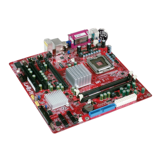
English System Board Layout PS/2 power select (JP1) Mouse DIMM 1 DIMM 2 COM1 +12V power power Parallel Parallel USB 0 USB 1 USB 0-3 power select (JP3) CPU fan Realtek Intel USB 2 RTL8111C USB 3 2nd fan Mic-in Line-in Line-out Battery... -
Seite 8: English
English Chapter 1 - Introduction Specifications • LGA 775 socket for: Processor - Intel Core 2 Quad / Intel Core 2 Duo ® ® - Intel Wolfdale 45nm processors ® • Supports Intel Enhanced Memory 64 Technology (EMT64T) • Supports Enhanced Intel SpeedStep Technology (EIST) • 1333/1066/800MHz FSB Chipset • Intel chipset ® - Northbridge: Intel G41 Express chipset ® - Southbridge: Intel ICH7 I/O Controller Hub ® • Two 240-pin DDR3 DIMM sockets System Memory • Supports DDR3 800/1066MHz • Supports maximum memory bandwidth of 17GB/s in dual- channel mode when using DDR3 1066MHz... - Seite 9 English I/O Connectors • 2 connectors for 4 additional external USB 2.0/1.1 ports • 1 connector for an external serial port • 1 front audio connector • 1 CD-in internal audio connector • 1 S/PDIF-out connector • 4 Serial ATA connectors • 1 40-pin IDE connector • 1 FDD connector • 1 24-pin ATX power connector • 1 4-pin 12V power connector • 1 chassis open connector • 1 front panel connector • 3 fan connectors BIOS • Award BIOS • 8Mbit SPI interface BIOS Energy Efficient • Supports ACPI specification and OS Directed Power Manage- Design ment • Supports ACPI STR (Suspend to RAM) function • Wake-On-Events include: - Wake-On-PS/2 Keyboard/Mouse - Wake-On-USB Keyboard/Mouse - Wake-On-LAN - Wake-On-Ring - RTC timer to power-on the system • System power management supported • Microsoft /Intel APM 1.2 compliant ®...
-
Seite 10: Chapter 2 - Hardware Installation
English Chapter 2 - Hardware Installation Jumper Settings Clear CMOS Data Parallel 1-2 On: Normal 2-3 On: (default) Clear CMOS Data If you encounter the following, a) CMOS data becomes corrupted. b) You forgot the supervisor or user password. you can reconfigure the system with the default values stored in the ROM BIOS. To load the default values stored in the ROM BIOS, please follow the steps below. 1. Power-off the system and unplug the power cord. 2. Set JP5 pins 2 and 3 to On. Wait for a few seconds and set JP5 back to its default setting, pins 1 and 2 On. - Seite 11 English PS/2 Power Select 1-2 On: 5V 2-3 On: (default) 5V_standby Parallel JP1 is used to select the power of the PS/2 keyboard/mouse port. Selecting 5V_standby will allow you to use the PS/2 keyboard or PS/2 mouse to wake up the system. BIOS Setting Configure the PS/2 keyboard/mouse wake up function in the Integrated Periph- erals submenu (“Super IO Device” section) of the BIOS. Refer to chapter 3 for more information.
- Seite 12 English USB Power Select Parallel USB 0-3 (JP3) 1-2 On: 5V 2-3 On: (default) 5V_standby USB 4-7 (JP2) 2-3 On: 1-2 On: 5V 5V_standby (default) These jumpers are used to select the power of the USB ports. Selecting 5V_ standby will allow you to use a USB device to wake up the system. BIOS Setting “USB KB Wake-Up From S3” in the Power Management Setup submenu of the BIOS must be set to Enabled. Refer to chapter 3 for more information.
- Seite 13 English Rear Panel I/O Ports PS/2 Parallel Mouse Mic-in USB 1 Line-in Line-out PS/2 K/B COM 1 USB 0 USB 2-3 PS/2 Ports and Parallel Port PS/2 Mouse PS/2 KB Parallel Parallel PS/2 Mouse and PS/2 Keyboard Ports These ports are used to connect a PS/2 mouse and a PS/2 keyboard. Parallel Port The parallel port is for interfacing your PC to a parallel printer. It supports SPP, ECP and EPP.
- Seite 14 English COM and VGA Ports Parallel COM 1 COM 2 1 2 3 4 5 6 7 8 9 COM 2 COM 1 COM Ports The serial ports are RS232 asynchronous communication ports with 16C550A- compatible UARTs that can be used with modems, serial printers, remote display terminals, and other serial devices.
- Seite 15 English USB and LAN Ports Parallel USB 1 USB 0 USB 3 USB 2 USB 4-5 USB 6-7 The USB ports are used to connect USB 2.0/1.1 devices. The 10-pin connectors allow you to connect 4 additional USB 2.0/1.1 ports. Your USB ports may come mounted on a card-edge bracket. Install the card-edge bracket to an available slot at the rear of the system chassis then connect the USB port cables to these connectors.
- Seite 16 English Audio Rear audio Parallel Mic-in Line-in Line-out Front audio 1 Rear Audio The system board is equipped with 3 audio jacks. A jack is a one-hole connecting interface for inserting a plug. • Mic-in Jack (Pink) This jack is used to connect an external microphone. • Line-in Jack (Light Blue) This jack is used to connect any audio devices such as Hi-fi set, CD player, tape player, AM/FM radio tuner, synthesizer, etc. • Line-out Jack (Lime) This jack is used to connect a headphone or external speakers. Front Audio The front audio connector allows you to connect to the second line-out and mic- in jacks that are at the front panel of your system.
-
Seite 17: Cd-In And S/Pdif-Out Connectors
English Internal I/O Connectors CD-in and S/PDIF-Out Connectors CD-in Right audio channel Parallel Ground Ground Left audio channel SPDIF out Ground N. C. S/PDIF-out CD-in The CD-in connector is used to receive audio from a CD-ROM drive, TV tuner or MPEG card. S/PDIF-Out The S/PDIF-out connector is used to connect an external S/PDIF-out port. Your S/PDIF port may be mounted on a card-edge bracket. Install the card-edge bracket to an available slot at the rear of the system chassis then connect the audio cable to the S/PDIF-out connector. Make sure pin 1 of the audio cable is... -
Seite 18: Serial Ata Connectors
English Serial ATA Connectors Parallel SATA 4 SATA 3 SATA 2 SATA 1 The Serial ATA connectors are used to connect Serial ATA devices. Connect one end of the Serial ATA cable to a SATA connector and the other end to your Serial ATA device. Chassis Instrusion Connector Parallel Signal Ground The board supports the chassis intrusion detection function. Connect the chas- sis intrusion sensor cable from the chassis to this connector. When the system’s power is on and a chassis intrusion occurred, an alarm will sound. When the system’s power is off and a chassis intrusion occurred, the alarm will sound only... - Seite 19 English FDD Connector and IDE Connector Parallel FDD Connector The floppy disk drive connector is used to connect a floppy drive. Insert one end of the floppy cable into this connector and the other end-most connector to the floppy drive. The colored edge of the cable should align with pin 1 of this con- nector.
- Seite 20 English Cooling Fan Connectors Parallel Ground Power Sense 2nd fan Ground Power CPU fan Sense System fan Speed Ground Control Power Sense These fan connectors are used to connect cooling fans. Cooling fans will provide adequate airflow throughout the chassis to prevent overheating the CPU and sys- tem board components. Downloaded from www.Manualslib.com manuals search engine...
-
Seite 21: Power Connectors
English Power Connectors 12 24 +3.3VDC +5VDC +12VDC +5VDC +12VDC Parallel +5VDC +5VSB PWR_OK +5VDC PS_ON# +5VDC +3.3VDC -12VDC +3.3VDC +3.3VDC ATX power +12V +12V 12V power Ground Ground Use a power supply that complies with the ATX12V Power Supply Design Guide Version 1.1. An ATX12V power supply unit has a standard 24-pin ATX main power connector that must be inserted into the 24-pin connector. The 4-pin +12V power connector enables the delivery of more +12VDC current to the processor’s Volt-... -
Seite 22: Expansion Slots
English Standby Power LED Parallel Standby Power LED This LED will light when the system’s standby power is on. Expansion Slots Parallel PCI Express x16 PCI Express x1 PCI 1 PCI 2 Downloaded from www.Manualslib.com manuals search engine... - Seite 23 English Front Panel Connectors Parallel PWR-BTN PWR-LED HDD-LED RESET-SW HDD-LED - HDD LED This LED will light when the hard drive is being accessed. RESET SW - Reset Switch This switch allows you to reboot without having to power off the system. PWR-BTN - Power Switch This switch is used to power on or off the system. PWR-LED - Power/Standby LED When the system’s power is on, this LED will light. When the system is in the S1 (POS - Power On Suspend) state, it will blink every second. When the system is in the S3 (STR - Suspend To RAM) state, it will blink every 4 seconds.
- Seite 24 English Battery Parallel Battery Downloaded from www.Manualslib.com manuals search engine...
-
Seite 25: Français
Français Français Chapitre 1 - Spécifications Processeur • LGA 775 socket pour: - Intel Core 2 Quad et Intel Core 2 Duo ® ® - Intel Wolfdale 45nm CPU ® • Intel Ont augmenté La Technologie De la Mémoire 64 (EMT64T) • Ont augmenté La Technologie D’Intel SpeedStep (EIST) • Soutient 1333/1066/800MHz FSB Chipset • Intel chipset ®... - Seite 26 Français Interne I/O • 2 connecteurs pour 4 ports USB 2.0/1.1 supplémentaires • 1 connecteur pour 1 série • 1 connecteur audio frontal • 1 connecteur CD-in audio internes • 1 connecteur S/PDIF-out • 4 connecteurs Serial ATA • 1 connecteur IDE • 1 connecteur de FDD • 1 connecteur d’alimentation ATX 24-pin • 1 connecteur d’alimentation ATX 4-pin 12V 1 connecteur de châssis ouvert • 1 connecteur devant panneau • 3 connecteurs de ventilateurs BIOS • Award BIOS • 8Mbit SPI interface BIOS Gestion de • ACPI et OS Directed Power Management Puissance • ACPI STR (Suspend to RAM) fonction • Réveil-Sur-PS/2 Clavier/Souris • Réveil-Sur-USB Clavier/Souris • Eveil Sonnerie • Réveil Par Le Réseau • Minuterie RTC pour allumer le système • Gestion intelligente de l’alimentation. • Compatible avec Microsoft /Intel APM 1.2 ® ® • Gestion avancée de l’alimentation – compatible avec ACPI v3.0b • Récupération après Défaillance d’Alimentation CA Fonctions de Moni-...
- Seite 27 Français Chapitre 2 - Installation de Matériel Cavalier Effacer les Données CMOS Parallel 1-2 On: Normal 2-3 On: (défaut) Effacer les données CMOS Si vous rencontrez les éléments suivants, a) Données CMOS devenant corrompues b) Vous avez oublié le superviseur ou le mot de passe utilisateur Vous devez reconfigurer le système aux valeurs par défaut stockées dans la ROM BIOS. Pour charger les valeurs par défaut dans la ROM BIOS, veuillez suivre les étapes ci-dessous.
- Seite 28 Français Sélectionner l’alimentation PS/2 1-2 On: 5V 2-3 On: (défaut) 5VSB Parallel En sélectionnant 5VSB, vous pourrez utiliser le clavier PS/2 ou la souris PS/2 pour “réveiller” le système. Important: La source d’alimentation 5VSB de votre alimentation doit supportée ≥720mA. Downloaded from www.Manualslib.com manuals search engine...
- Seite 29 Français Sélectionner l’alimentation USB Parallel USB 0-3 (JP3) 1-2 On: 5V 2-3 On: 5VSB (défaut) USB 4-7 (JP2) 1-2 On: 5V 2-3 On: (défaut) 5VSB En sélectionnant 5VSB, vous pourrez utiliser le clavier USB ou la souris USB pour “réveiller” le système. Important: La source d’alimentation 5VSB de votre alimentation doit supportée ≥1,5(2 ports) ou ≥2 A(3 ou davantage de ports). Downloaded from www.Manualslib.com manuals search engine...
- Seite 30 Français Ports I/O de l’arrière du Panneau souris parallèle PS/2 Mic-in USB 1 Line-in Line-out clavier PS/2 USB 0 USB 2-3 COM 1 Ports PS/2 et parallèle PS/2 Mouse PS/2 KB Parallel parallèle Ports Souris PS/2 et Clavier PS/2 Ces ports sont utilisés pour raccorder une souris PS/2 et un clavier PS/2. Port parallèle Le port parallèle sert d’interface à votre PC pour le branchement d’une imprim- ante. SPP, ECP et EPP compatible.
- Seite 31 Français Ports COM et VGA Parallel COM 1 COM 2 1 2 3 4 5 6 7 8 9 COM 2 COM 1 Ports COM Les ports série de type RS232 permettent une communication sérielle, asyn- chrone avec haute performance 16C550A compatible aux gardes UART utilis- ables dans le cas de modems, d’imprimantes en série, d’affichage à distance et d’autres périphériques série.
-
Seite 32: Ports Lan
Français Ports USB et LAN Parallel USB 1 USB 0 USB 3 USB 2 USB 4-5 USB 6-7 Ports USB Les ports USB sont utilisés pour raccorder des appareils USB 2.0/1.1. Les con- necteurs 10 broches vous permettent de raccorder 4 autres ports USB 2.0/1.1. Vos ports USB peuvent être livrés montés sur un support encartable. Installer le support encartable dans une fente disponible à l’arrière du châssis du système et raccorder les câbles des ports USB à ces connecteurs. - Seite 33 Français Audio Rear audio Parallel Mic-in Line-in Line-out Connecteur audio frontal Audio arrière La carte est dotée de 3 prises jack audio. La prise jack est une interface de rac- cordement à un orifice pour introduire une fiche. Prise entrée micro (rose) Cette prise est utilisée pour connecter un microphone externe. Prise entrée (bleue claire) La prise est utilisée pour raccorder tous les appareils audio tels que Hi-fi, lec- teur CD, lecteur de bande magnétique, radio AM/FM, synthéthiseur, etc..
- Seite 34 Français Connecteurs I/O Connecteurs de CD-in et S/PDIF-Out CD-in Right audio channel Parallel Ground Ground Left audio channel SPDIF out Ground N. C. S/PDIF-out Connecteur d’entrée CD Le connecteur d’entrée CD est utilisé pour recevoir les signaux audio d’un lecteur CD-ROM, d’une carte TV ou MPEG. Sortie S/PDIF Le connecteur S/PDIF permet la connexion à un port extérieur S/PDIF. Le port S/ PDIF peut être monté sur une barrette de connexion. Installez la barrette de con- nexion à un slot disponible à l’arrière du châssis de l’équipement puis, branchez le câble audio au connecteur de sortie S/PDIF. Veillez à ce que la broche 1 du...
- Seite 35 Français Les Connecteurs en Série ATA Parallel SATA 4 SATA 3 SATA 2 SATA 1 Les connecteurs en série ATA (SATA) sont utilisés pour raccorder les disques durs ATA en série. Relier une extrémité du câble en série ATA au connecteur en série ATA et l’autre extrémité sur votre appareil en série ATA. Connecteur d’intrusion châssis Parallel Signal Ground La carte supporte la fonction de détection d’intrusion châssis Branchez le câble du bouton contact d’intrusion châssis de ce dernier à ce connecteur. Lorsque l’appareil est sous tension, une alarme retentit si le châssis est ouvert. Si le châssis est ouvert lorsque l’appareil est hors tension, l’alarme retentira unique-...
- Seite 36 Français Connecteur de Lecteur de Disquettes et Connecteur IDE Parallel Connecteur de Lecteur de Disquettes Le connecteur de lecteur de disquettes est utilisé pour raccorder le lecteur de disquettes. Il possède un mécanisme d’insertion qui empêche sa mauvaise instal- lation. Insérer une extrémité du câble du lecteur de disquette dans ce connecteur et l’autre dans le lecteur de disquette. Le bord coloré du câble devrait être aligné avec l’ergot 1 de ce connecteur. Connecteur de Disque dur IDE Le connecteur de disque dur IDE est utilisé pour raccorder 2 disques IDE. Il pos- sède un mécanisme d’insertion qui empêche la mauvaise installation du cable IDE. Un câble IDE comporte 3 connecteurs, un qui se branche sur ce connect- eur et les deux autres qui se connectent sur les appareils IDE. Le connecteur à...
- Seite 37 Français Connecteurs de Ventilateur de Refroidissement Parallel Ground Power Sense 2nd fan Ground Power CPU fan Sense System fan Speed Ground Control Power Sense Ces connecteurs de ventilateur sont utilisés pour raccorder les ventilateurs de refroidissement. Les ventilateurs de refroidissement fournissent une ventilation adéquate à l’intérieur du châssis afin d’empêcher toute surchauffe du processeur et des composants de la carte système.
-
Seite 38: Connecteurs D'alimentation
Français Connecteurs d’alimentation 12 24 +3.3VDC +12VDC +5VDC +5VDC +12VDC Parallel +5VDC +5VSB PWR_OK +5VDC +5VDC PS_ON# -12VDC +3.3VDC +3.3VDC +3.3VDC ATX power +12V +12V 12V power Ground Ground Utilisation d’une alimentation électrique conforme aux caractéristiques de ATX12V Power Supply Design Guide Version 1.1. Une alimentation ATX12V dispose d’un connecteur ATX 24 broches standard d’alimentation principale qui doit être in- troduit dans le connecteur 24 broches. Le connecteur d’alimentation + 12 V à... - Seite 39 Français Voyant DEL d’alimentation à l’état de veille Parallel V o y a n t D E L d’alimentation à l’état de veille Ce voyant DEL s’allumera lorsque le système est en mode veille. Logements d’Extension Parallel PCI Express x16 PCI Express x1 PCI 1 PCI 2 Downloaded from www.Manualslib.com manuals search engine...
- Seite 40 Français Connecteurs Frontaux du Panneau Parallel PWR-BTN PWR-LED HDD-LED RESET-SW HDD-LED - HDD LED Ce voyant LED s’illumine lorsque votre disque dur est en service. RESET SW - Interrupteur de Reset Cet interrupteur permet de redémarrer sans avoir à éteindre le système. PWR-BTN - Interrupteur d’alimentation Cet interrupteur permet d’allumer ou d’éteindre le système. PWR-LED: Voyant DEL d’alimentation / état de veille Ce voyant DEL s’allumera lorsque le système est allumé. Lorsque le système est sur le statut S1 (POS – alimentation suspendue) ou S3 (STR – suspendue dans la RAM), il clignotera toutes les secondes.
- Seite 41 Français Batterie Parallel Batterie Downloaded from www.Manualslib.com manuals search engine...
-
Seite 42: Deutsch
Deutsch Deutsch Kapitel 1 - Spezifikation Prozessor • LGA 775 CPU Einfaßung für: - Intel Core 2 Quad und Intel Core 2 Duo ® ® - Intel Wolfdale 45nm CPU ® • Intel Erhöhten Technologie Des Gedächtnis-64 (EMT64T) • Erhöhten Intel SpeedStep Technologie (EIST) •... - Seite 43 Deutsch Internes I/O • 2 Anschlußfassung für 4 zusätzliche externe USB 2.0- Anschlüsse • 1 Anschluß für eine externe serieller DB-9-Anschluß • 1 Front-Audioanschluss • 1 interne Audioanschlüsse (CD-in) • 1 SPDIF-out-Anschluß • 4 Serial-ATA-Anschlüsse • 1 IDE-Anschlüsse • 1 Floppy-Anschlüsse •...
-
Seite 44: Kapitel 2 - Installieren Des Hardware
Deutsch Kapitel 2 - Installieren des Hardware Jumper Löschen der CMOS Daten Parallel 1-2 On: Normal 1-2 On: Normal (Standardwert) (Standardwert) Sollten Sie eins der folgenden Probleme haben, a) die CMOS Daten sind beschädigt. b) Sie haben das Supervisor oder User Passwort vergessen. so können Sie das System mit den im ROM BIOS gespeicherten Standardwerten rekonfigurieren. - Seite 45 Deutsch PS/2 Power Select 1-2 On: 5V 2-3 On: (Standard) 5VSB Parallel Die Auswahl von 5VSB erlaubt es Ihnen, Ihr System per PS/2 Keyboard oder PS/2 Maus aufzuwecken. Wichtig: Die 5VSB Stromquelle Ihres Netzteils muss ≥720mA unterstützen. Downloaded from www.Manualslib.com manuals search engine...
- Seite 46 Deutsch USB Power Select Parallel USB 0-3 (JP3) 1-2 On: 5V 2-3 On: 5VSB (Standard) USB 4-7 (JP2) 1-2 On: 5V 2-3 On: 5VSB (Standard) Die Auswahl von 5VSB erlaubt es Ihnen, Ihr System per USB Keyboard oder USB Maus aufzuwecken. Wichtig: Die 5VSB Stromquelle Ihres Netzteils muss ≥1.5V (2 ports) oder ≥2V (3 oder mehr Ports) Vunterstützen.
- Seite 47 Deutsch Rückseite I/O Ports PS/2 Parallel Mouse Mic-in USB 1 Line-in Line-out USB 0 USB 2-3 PS/2 K/B COM 1 PS/2 Ports und Parallel Ports PS/2 Mouse PS/2 KB Parallel Parallel PS/2 Maus und PS/2 Keyboard Ports Diese Ports werden zum Anschluss von PS/2 Maus und PS/2 Keyboard verwendet. Parallel-Port Der Parallel-Port ist zum Anschluss eines Paralleldruckers an Ihren PC.
-
Seite 48: Com Und Vga Ports
Deutsch COM und VGA Ports Parallel COM 1 COM 2 1 2 3 4 5 6 7 8 9 COM 2 COM 1 COM Ports Die seriellen Ports sind asynchrone RS232 Kommunikationsports mit 16C550A- fähigen UARTs, die mit Modem, seriellen Druckern, fernverarbeitendem Datensi- chtgerät und anderen seriellen Geräten genutzt werden können. -
Seite 49: Usb Ports Und Lan Ports
Deutsch USB Ports und LAN Ports Parallel USB 1 USB 0 USB 3 USB 2 USB 4-5 USB 6-7 USB Ports Über die USB Ports verbinden Sie USB 2.0/1.1 Geräte. Die 10-Pin Anschlüsse erlauben Ihnen den Anschluss von 6 zusätzlichen USB 2.0/1.1 Ports. Ihre USB Ports könnten auf einem Halterungsblech befestigt sein. - Seite 50 Deutsch Audio Rückseitiges Audio Parallel Mic-in Line-in Line-out Front audio 1 Rückseitiges Audio Das Systemboard ist mit 3 Audiobuchsen ausgestattet. Eine Buchse ist ein One- Hole Verbindungs-Interface zum Einstecken eines Steckers. Mic-in Stecker (Pink) Mit diesem Stecker verbinden Sie ein externes Mikrophon mit dem System. Line-in Stecker (Hellblau) Mit diesem Stecker verbinden Sie beliebige Audiogeräte wie z.B.
-
Seite 51: Cd-In Und S/Pdif-Out Anschlüsse
Deutsch I/O Anschlüsse CD-in und S/PDIF-Out Anschlüsse CD-in Right audio channel Parallel Ground Ground Left audio channel SPDIF out Ground N. C. S/PDIF-out CD-in Anschluss Der CD-in Anschluss wird verwendet, um Audio von einem CD-ROM Laufwerk, einer TV Tuner oder MPEG-Karte zu empfangen. /PDIF-Ausgang Die S/PDIF-Ausgangbuchse dient dem Anschluss an einen externen S/PDIF- Ausgangsport. -
Seite 52: Serial Ata Anschlüsse
Deutsch Serial ATA Anschlüsse Parallel SATA 4 SATA 3 SATA 2 SATA 1 Über die Serial ATA (SATA) Anschlüsse werden Serial ATA Laufwerke angeschlos- sen. Verbinden Sie das eine Ende des Serial ATA Kabels mit dem Serial ATA An- schluss und das andere Ende mit Ihrem Serial ATA Gerät. Gehäuse-Intrusion-Anschluss Parallel Signal... -
Seite 53: Floppy Disk Drive Anschluss Und Ide Anschluss
Deutsch Floppy Disk Drive Anschluss und IDE Anschluss Parallel Floppy Disk Drive Anschluss Über den Floppy Disk Drive Anschluss werden Floppy-Laufwerke angeschlossen. Er verfügt über einen Verbindungsmechanismus der eine Fehlinstallation ver- meidet. Verbinden Sie ein Ende des Floppy-Kabels mit dem Anschluss auf dem Board und das andere Ende mit dem Floppy-Laufwerk. - Seite 54 Deutsch Lüfteranschlüsse Parallel Ground Power Sense 2nd fan Ground Power CPU fan Sense System fan Speed Ground Control Power Sense Über diese Lüfteranschlüsse werden Lüfter mit dem System verbunden. Diese Lüfter sorgen für ausreichende Luftzirkulation im Gehäuse und verhindern somit ein Überhitzen der CPU und der Komponenten auf dem Systemboard.
- Seite 55 Deutsch Stromanschlüsse 12 24 +3.3VDC +12VDC +5VDC +5VDC +12VDC Parallel +5VDC +5VSB PWR_OK +5VDC +5VDC PS_ON# -12VDC +3.3VDC +3.3VDC +3.3VDC ATX power +12V +12V 12V power Ground Ground Nutzen Sie eine Netzversorgung die den Vorgaben der ATX12V Power Supply De- sign Guide Version 1.1 übereinstimmt.
- Seite 56 Deutsch Standby Power LED Parallel Standby Power LED Diese LED leuchtet wenn das System im Standby Modus ist. Expansion Schlitz Parallel PCI Express x16 PCI Express x1 PCI 1 PCI 2 Downloaded from www.Manualslib.com manuals search engine...
- Seite 57 Deutsch Frontanschlüsse Parallel PWR-BTN PWR-LED HDD-LED RESET-SW HDD-LED - HDD LED Beim Zugriff auf Festplatten leuchtet die LED. RESET SW - Reset-Schalter Dieser Schalter ermöglicht ein Neustarten, ohne Herunterfahren des Systems. PWR-BTN - Netzschalter Dieser Schalter dient zum Ein- und Ausschalten des Systems. PWR-LED: Power/Standby LED Diese LED leuchtet, wenn die Stromzufuhr des Systems eingeschaltet ist.
- Seite 58 Deutsch Akku Parallel Akku Downloaded from www.Manualslib.com manuals search engine...
-
Seite 59: Italiano
Italiano Italiano Italiano Chapter 1 - Quick Guide Scheda Madre Questa guida rapida di installazione indica i passaggi principali per l’assemblaggio della scheda madre. Tutte le operazioni di assemblaggio della scheda madre richiedono che i prodotti collegati alla motherboard non siano connessi alla rete elettrica. Le operazioni di montaggio della motherboard richiedono personale tecnicamente addestrato. - Seite 60 Italiano Assicurarsi che l’alimentatore sia compatibile con la scheda madre che si sta as- semblando. Controllare sempre che l’alimentatore non sia connesso alla rete elettrica durante le fasi di assemblaggio. Collegare l’alimentatore alla scheda madre sugli appositi zoccoli. A fine assemblaggio verificare la correttezza di tutti i cablaggi ed inserzioni. La scheda madre integra diverse porte di comunicazione nello schema accanto vi- ene riportato un esempio de connettori che possono essere dislocati sul pannello di input/output della scheda madre.
- Seite 61 Italiano Esempi di Disposizione Downloaded from www.Manualslib.com manuals search engine...
- Seite 62 Italiano Capitolo 2 - Introduzione Specifiche Processore • Presa LGA 775 per: - Intel Core 2 Quad e Intel Core 2 Duo ® ® - Intel Wolfdale 45nm CPU ® • Supporta tecnologia Intel Enhanced Memory 64 Technol- ogy (EMT64T) • Supporta tecnologia Enhanced Intel SpeedStep Technology (EIST) • Supporta FSB 1333/1066/800MHz Chipset • chipset Intel ®...
- Seite 63 Italiano I/O interno • 2 connettori per 4 porte USB 2.0 esterne addizionali • 1 connettore per una porta COM esterna • 1 connettore audio frontale • 1 connettore CD-in • 1 connettore SPDIF-out • 4 connettori ATA Seriali • 1 connettore IDE a 40 pin •...
- Seite 64 Italiano Capitolo 3 - Installazione hardware Impostazioni jumper Eliminazione dei dati CMOS Parallel On:Normale 2-3On: Eliminazione (default) dati CMOS Se si verifica quanto segue, a) i dati CMOS verranno corrotti. b) Smarrimento della password utente o supervisore. è possibile configurare il sistema con i valori predefiniti memorizzati Sul BIOS ROM.
- Seite 65 Italiano Selezione di alimentazione PS/2 1-2 On: 5V 2-3 On: (default) 5VSB Parallel Selezionando 5VSB, è possibile usare la tastiera PS/2 o il mouse PS/2 per at- tivare il sistema Importante: La fonte di alimentazione 5VSB in uso deve supportare ≥720mA. Downloaded from www.Manualslib.com manuals search engine...
- Seite 66 Italiano Selezione di alimentazione USB Parallel USB 0-3 (JP3) 2-3 On: 5VSB 1-2 On: 5V (default) USB 4-7 (JP2) 1-2 On: 5V 2-3 On: 5VSB (default) Selezionando 5VSB, è possibile usare la tastiera USB o il mouse USB per attivare il sistema.
- Seite 67 Italiano Rear Panel I/O Ports PS/2 parallela Mouse Mic-in USB 1 Line-in Line-out USB 0 USB 2-3 PS/2 K/B COM 1 Porte PS/2 e S/PDIF PS/2 Mouse PS/2 KB Parallel parallela Porte del mouse PS/2 e della tastiera PS/2 Queste porte servono per collegare un mouse PS/2 e una tastiera PS/2. Parallel Port La porta parallela serve per interfacciare il PC con una stampante in parallelo Supporta SPP, ECP e PPP.
- Seite 68 Italiano Porte COM e VGA Parallel COM 1 COM 2 1 2 3 4 5 6 7 8 9 COM 2 COM 1 Porte COM Le porte seriali sono porte di comunicazione asincrona RS232 dotate di UART compatibili 16C550A che possono essere utilizzate con modem, stampanti seriali, terminali display remoti e altri dispositivi seriali.
-
Seite 69: Porta Lan
Italiano Porte USB e porta LAN Parallel USB 1 USB 0 USB 3 USB 2 USB 4-5 USB 6-7 Porte USB Le porte USB servono per collegare i dispositivi USB 2.0/1.1. I connettori a 10 pin permettono di collegare 4 porte USB 2.0/1.1 addizionali.Le porte USB pos- sono includere una staffa con finitura in cartone. - Seite 70 Italiano Audio audio posteriore Parallel Mic-in Line-in Line-out Front audio 1 audio anteriore Audio posteriore La scheda di sistema è dotata di 3 prese audio. Un jack è un’interfaccia di colle- gamento composta da un foro per l’inserimento di una spina. Line-in (azzurro) Questa presa serve per collegare i dispositivi audio, ad es.
-
Seite 71: Connettori Cd-In E Uscita S/Pdif
Italiano Connettori I/O interni Connettori CD-in e Uscita S/PDIF CD-in Right audio channel Parallel Ground Ground Left audio channel SPDIF out Ground N. C. Uscita S/PDIF CD-in Il connettore CD-in serve per ricevere l`audio da un`unità CD-ROM, sintonizza- tore TV o scheda MPEG. Uscita S/PDIF Il connettore di uscita S/PDIF viene utilizzato per il collegamento di una porta S/PDIF in uscita. - Seite 72 Italiano Connettori ATA Seriali Parallel SATA 4 SATA 3 SATA 2 SATA 1 I connettori ATA Seriali (SATA) servono per collegare le unità ATA Seriali. Col- legare un`estremità del cavo ATA Seriale a un connettore ATA Seriale e l`altra estremità al dispositivo ATA Seriale. Connettore di intrusione del telaio Parallel Signal...
- Seite 73 Italiano Connettore FDD e connettore IDE Parallel Connettore FDD Il connettore dell`unità floppy disk serve per collegare un`unità floppy. Inserire un`estremità del cavo floppy disk nel connettore e l`altra estremità all`unità del floppy. L`estremità colorata del cavo deve essere allineata al pin 1 di questo con- nettore.
- Seite 74 Italiano Connettori della ventola di raffreddamento Parallel Ground Power Sense 2nd fan Ground Power CPU fan Sense System fan Speed Ground Control Power Sense I connettori della ventola servono per collegare le ventole di raffreddamento. Le ventole di raffreddamento forniscono un flusso d`aria adeguato all`unità per im- pedirne il surriscaldamento della CPU e dei componenti della scheda di sistema.
- Seite 75 Italiano Connettori di alimentazione 12 24 +3.3VDC +12VDC +5VDC +5VDC +12VDC Parallel +5VDC +5VSB PWR_OK +5VDC +5VDC PS_ON# -12VDC +3.3VDC +3.3VDC +3.3VDC ATX power +12V +12V 12V power Ground Ground Si prega di servirsi di una fonte d’alimentazione conforme con la Guida alla forni- tura di alimentazione di ATX12V, versione 1.1.
- Seite 76 Italiano LED di alimentazione Standby Parallel LED di ali- mentazione Standby Questo LED si accenda quando il sistema è in modalità Standby. Slot di espansione Parallel PCI Express x16 PCI Express x1 PCI 1 PCI 2 Downloaded from www.Manualslib.com manuals search engine...
- Seite 77 Italiano Connettori del pannello anteriore Parallel PWR-BTN PWR-LED HDD-LED RESET-SW HDD-LED - HDD LED Questa spia LED si illuminerà quando si esegue l’accesso al disco rigido. RESET SW - Tasto reset Questo tasto consente di riavviare il sistema senza doverlo spegnere. PWR-BTN - Interruttore di accensione/spegnimento Questo interruttore viene utilizzato per accendere o spegnere il sistema.
- Seite 78 Italiano Pila Parallel Pila Downloaded from www.Manualslib.com manuals search engine...
-
Seite 79: Español
Español Español Español Chapter 1 - Especificaciones Procesador • LGA 775 Zócalo de la CPU para: - Intel CoreTM2 Quad y Intel CoreTM2 Duo ® ® - Intel Wolfdale 45nm CPU ® • Intel Realzaron Tecnología De la Memoria 64 (EMT64T) • Realzaron La Tecnología De Intel SpeedStep (EIST) • 1333/1066/800MHz FSB Chipset • Intel chipset ® - Puente norte: Intel G41 Express Chipset ® - Puente sur: Intel ICH7 I/O Controller Hub ® Memoria • 2 240-pin mortajas DDR3 DIMM de Sistema... - Seite 80 Español Conectador Interno • 2 conectors para 4 puertos de USB 2.0 externo adicional • 1 conector para un puerto de DB-9 serie externa • 1 connector de sonido delantera • 1 conector de CD-in audio interno • 1 conector de SPDIF-out • 4 conectores de Serial ATA • 1 conector de IDE • 1 conector de FDD • 1 conectore de 24-pin fuente de alimentación de ATX • 1 conectore de 4-pin 12V fuente de alimentación de ATX • 1 conector abierto en el chasis • 1 conector de panel delante • 3 conectores de abanicos BIOS • Award BIOS • 8Mbit SPI interface BIOS Gerencia de la En- • ACPI y OS Directed Power Management ergía • ACPI STR (Suspend to RAM) función • PS/2 Teclado/Ratón de Wake-On • USB Teclado/Ratón de Wake-On • Wake-On-Ring • Wake-On-LAN • Temporizador de RTC para encender el sistema • Permite la Administración de Energía del Sistema • Compatible con Microsoft /Intel APM 1.2 ® ® • Admite Soft Power - Especificación ACPI v3.0b • Recuperación de Fracaso de Energía AC Monitor del Hard- • Monitores de los CPU/System/AUX temperaturas y alarma ware acalorada.
-
Seite 81: Chapter 2 - Instalación Del Hardware
Español Chapter 2 - Instalación del Hardware Puente Borrar Datos CMOS Parallel 1-2 On (encen- 2-3 On (encendido): dido): Normal Borrar datos CMOS (predeterminado) En alguno de los siguientes casos, a) los datos CMOS se corrompen. b) ha olvidado la contraseña del supervisor o del usuario. Se puede configurar nuevamente el sistema con los valores predeterminados al- macenados en la ROM BIOS. Para cargar los valores predeterminados almacenados en la ROM BIOS, siga los siguientes pasos. - Seite 82 Español Selector de Alimentación PS/2 1-2 On: 5V 2-3 On: (predeterminado) 5VSB Parallel Seleccionar 5VSB le permitirá utilizar el teclado PS/2 o el ratón PS/2 para des- pertar el sistema. Importante: La fuente de alimentación 5VSB de suministro eléctrico debe admitir ≥720mA. Downloaded from www.Manualslib.com manuals search engine...
- Seite 83 Español Selector de Alimentación USB Parallel USB 0-3 (JP3) 1-2 On: 5V 2-3 On: 5VSB (predeterminado) USB 4-7 (JP2) 1-2 On: 5V 2-3 On: (predeterminado) 5VSB Seleccionar 5VSB le permitirá utilizar el teclado USB o el ratón USB para desper- tar el sistema. Importante: La fuente de alimentación 5VSB de suministro eléctrico debe admitir ≥1.5A.(2 puertos) o ≥A (3 o más puertos USB).
- Seite 84 Español Puertos I/O del Panel Posterior ratón paralelo PS/2 Mic-in USB 1 Line-in Line-out teclado COM 1 USB 0 USB 2-3 PS/2 Puertos PS/2 y Puertos paralelo PS/2 Mouse PS/2 KB Parallel paralelo Puertos para Ratón PS/2 y Teclado PS/2 Estos puertos se utilizan para conectar un ratón PS/2 y un teclado PS/2. Puerto paralelo El puerto paralelo es para conectar su PC a una impresora en paralelo. Admite SPP, ECP y EPP.
- Seite 85 Español Puertos COM y VGA Parallel COM 1 COM 2 1 2 3 4 5 6 7 8 9 COM 2 COM 1 Puerto COM Los puertos en serie son puertos RS232 de comunicación asíncrona con UART compatible con 16C550A que pueden usarse con módems, impresoras en serie, terminales de visualización remota y otros dispositivos en serie.
-
Seite 86: Puertos Lan
Español Puertos USB y Puertos LAN Parallel USB 1 USB 0 USB 3 USB 2 USB 4-5 USB 6-7 Puertos USB Los puertos USB se utilizan para conectar dispositivos USB 2.0/1.1 El conector de 10 pines permite conectar 4 puertos USB 2.0/1.1 adicionales. El puerto USB puede presentarse montado en un soporte con bordes de placa. Instale dicho soporte en una ranura disponible en la parte trasera del armazón del sistema, luego conecte los cables del puerto USB a estos conectores. - Seite 87 Español Audio Rear audio Parallel Mic-in Line-in Line-out Conector de audio frontal Audio en la parte posterior La tarjeta del sistema está provista de 3 enchufes de audio. Un enchufe es una interfaz de conexión con un agujero para insertar un conector. Enchufe de entrada de micrófono (rosa) Este enchufe se utiliza para conectar un micrófono externo. Enchufe de entrada (azul claro) Este enchufe se utiliza para conectar cualquier dispositivo de audio, tal como un hi-fi, un reproductor de CD, un reproductor de cintas, sintonizador de ra-...
- Seite 88 Español Conectores I/O Conectores CD-in y S/PDIF-Out CD-in Right audio channel Parallel Ground Ground Left audio channel SPDIF out Ground N. C. S/PDIF-out Conector de entrada de CD El conector de entrada de CD se utiliza para recibir audio de un lector de CD- ROM, de un sintonizador de TV o de una placa MPEG.
- Seite 89 Español Conectores ATA Seriales Parallel SATA 4 SATA 3 SATA 2 SATA 1 Los conectores seriales ATA (SATA) se utilizan para conectar los transmisores ATA seriales. Conecte un extremo del cable ATA serial al conector ATA serial y el otro extremo al dispositivo ATA serial. Conector de intrusión en el chasis Parallel Signal Ground La tarjeta admite la función de detección de intrusión en el chasis. Conecte el cable del sensor de intrusión en el chasis del chasis a este conector. Cuando el sistema esté encendido y haya ocurrido la intrusión en el chasis, sonará una alar- ma. Cuando el sistema esté encendido y haya ocurrido la intrusión en el chasis,...
- Seite 90 Español Conector de la Unidad de Disco Flexible y Conector IDE Parallel Conector de Disco Flexible El conector de disco flexible de se utiliza para conectar una unidad de discos flexibles. Cuenta con un mecanismo de codificación para prevenir una instalación inadecuada del cable flexible. Inserte un extremo del cable flexible en este conec- tor y el otro conector del extremo a la unidad de discos flexibles. El extremo de color del cable debe estar alineado con el pin1 de este conector.
- Seite 91 Español Conectores de Ventiladores de Refrigeración Parallel Ground Power Sense 2nd fan Ground Power CPU fan Sense System fan Speed Ground Control Power Sense Estos conectores de ventiladores se utilizan para conectar ventiladores de refrig- eración. Los ventiladores de refrigeración proporcionan una circulación de aire ad- ecuada a través del armazón a fin de prevenir que recalienten los componentes de la placa de sistema y la CPU.
- Seite 92 Español Conectores de Electricidad 12 24 +3.3VDC +5VDC +12VDC +5VDC +12VDC Parallel +5VDC +5VSB PWR_OK +5VDC PS_ON# +5VDC +3.3VDC -12VDC +3.3VDC +3.3VDC ATX power +12V +12V 12V power Ground Ground Use una fuente de alimentación que cumpla con la versión 1.1 de la guía de dis- eño de la fuente de alimentación ATX12V. Una unidad de fuente de alimentación tiene un conector ATX de alimentación principal de 24 pines que debe insertarse en el conector de 24 pines. El conector de alimentación de +12V de 4 pines per-...
- Seite 93 Español LED de alimentación de reserva Parallel LED de ali- mentación de reserva Este LED se iluminará cuando el sistema se encuentre en modo de reserva. Ranuras de Expansión Parallel PCI Express x16 PCI Express x1 PCI 1 PCI 2 Downloaded from www.Manualslib.com manuals search engine...
- Seite 94 Español Conectores del Panel Frontal Parallel PWR-BTN PWR-LED HDD-LED RESET-SW HDD-LED - HDD LED Este LED se encenderá cuando se acceda al disco duro. RESET SW - Interruptor de reinicio Este interruptor le permite a usted reiniciar sin tener que apagar el sistema. PWR-BTN - Interruptor de energía Este interruptor se usa para encender o apagar el sistema. PWR-LED (LED de electricidad): LED de encendido/alimentación de reserva Este LED se iluminará cuando el sistema se encuentre encendido. Cuando el sistema se encuentre en estado S1 (POS – Encendido suspendido) o S3 (STR –...
- Seite 95 Español Batería Parallel Batería Downloaded from www.Manualslib.com manuals search engine...
-
Seite 96: Debug Led Post And Troubleshooting
Appendix A - Debug LED Post and Troubleshooting Debug LED POST and Troubleshooting Appendix A - Debug LED Post and Troubleshooting General Debug LED POST and Troubleshooting Downloaded from www.Manualslib.com manuals search engine... - Seite 97 Debug LED POST and Troubleshooting Downloaded from www.Manualslib.com manuals search engine...
- Seite 98 Debug LED POST and Troubleshooting Downloaded from www.Manualslib.com manuals search engine...
- Seite 99 Debug LED POST and Troubleshooting Downloaded from www.Manualslib.com manuals search engine...
- Seite 100 Debug LED POST and Troubleshooting Abnormal Debug LED POST and Troubleshooting Downloaded from www.Manualslib.com manuals search engine...