Herunterladen Diese Seite drucken

Werbung

Verfügbare Sprachen

Verfügbare Sprachen

Montage- und Betriebsanleitung
DEHNSPANNFUTTER HYDRO MILL CHUCK
HYDRAULIC CHUCK HYDRO MILL CHUCK
| Installation an Operating Instructions
| Installation an Operating Instructions
DE
DE
DE
EN
EN
EN

Werbung

loading

Inhaltszusammenfassung für Mapal hydraulic chuck

  • Seite 1 Montage- und Betriebsanleitung | Installation an Operating Instructions Montage- und Betriebsanleitung DEHNSPANNFUTTER HYDRO MILL CHUCK | Installation an Operating Instructions DEHNSPANNFUTTER HYDRO MILL CHUCK HYDRAULIC CHUCK HYDRO MILL CHUCK HYDRAULIC CHUCK HYDRO MILL CHUCK...
  • Seite 3 I I n n h h a a l l t t s s v v e e r r z z e e i i c c h h n n i i s s Z Z i i e e l l d d e e r r M M o o n n t t a a g g e e - - u u n n d d B B e e t t r r i i e e b b s s a a n n l l e e i i t t u u n n g g ................................................... . 4 4 K K o o n n t t a a k k t t .
  • Seite 4 Ausführung abweichen. K K o o n n t t a a k k t t MAPAL Fabrik für Präzisionswerkzeuge Dr. Kress KG Obere Bahnstraße 13 A A d d r r e e s s s s e e...
  • Seite 5 • Bei langen, auskragenden und schweren Werkzeugen oder beim Einsatz von Verlängerungen muss die maximale Be- triebsdrehzahl gemäß den individuellen Gegebenheiten reduziert werden. • Das Abweichen der Vorschriften kann zu Verletzungen oder Beschädigungen von Maschinen und Zubehör führen, für die MAPAL keine Haftung übernimmt. Montage- und Betriebsanleitung Montage- und Betriebsanleitung...
  • Seite 6 • Das Dehnspannfutter darf nicht für die Werkstückspannung eingesetzt werden. • Das Dehnspannfutter darf nicht verändert und für andere Anwendungen erschlossen werden. • Zusätzliche Bohrungen, Gewinde und Anbauten dürfen nur nach schriftlicher Genehmigung durch MAPAL angebracht werden. • Im Falle von eigenmächtigen Veränderungen am Dehnspannfutter oder einer nicht bestimmungsgemäßen Verwendung des Dehnspannfutters, erlischt der Gewährleistungsanspruch gegenüber MAPAL.
  • Seite 7  Die Grenzbelastbarkeit der maschinenseitigen Schnittstelle nach z. B. VDMA 34181 beachten.  Treten Unregelmäßigkeiten während der Bedienung auf, das Dehnspannfutter aus Sicherheitsgründen nicht mehr ein- setzen und es zur Überprüfung oder zur Reparatur an MAPAL senden. Montage- und Betriebsanleitung...
  • Seite 8 3 3 . . 5 5 . . 1 1 G G e e f f a a h h r r e e n n d d u u r r c c h h H H i i t t z z e e - - u u n n d d W W ä ä r r m m e e e e n n t t w w i i c c k k l l u u n n g g W W A A R R N N U U N N G G S S c c h h r r u u m m p p f f e e n n o o d d e e r r E E r r h h i i t t z z e e n n d d e e s s D D e e h h n n s s p p a a n n n n f f u u t t t t e e r r s s k k a a n n n n z z u u V V e e r r l l e e t t z z u u n n g g e e n n f f ü...
  • Seite 9 3 3 . . 5 5 . . 2 2 M M e e c c h h a a n n i i s s c c h h e e G G e e f f a a h h r r e e n n W W A A R R N N U U N N G G S S p p a a n n n n e e n n u u n n d d E E n n t t s s p p a a n n n n e e n n b b e e i i l l a a u u f f e e n n d d e e r r M M a a s s c c h h i i n n e e ! ! Durch das Spannen und Entspannen des Dehnspannfutters bei laufender Maschine können schwere Verletzungen des...
  • Seite 10 Einsatz kommen.  Nicht die versiegelte Entlüftungsschraube beschädigen oder öffnen.  Bei beschädigter Entlüftungsschraube das Dehnspannfutter aus Sicherheitsgründen nicht mehr einsetzen.  Bei Beschädigung zur Überprüfung und Reparatur an MAPAL senden. Montage- und Betriebsanleitung Montage- und Betriebsanleitung...
  • Seite 11 H H I I N N W W E E I I S S V V e e r r s s c c h h l l e e i i ß ß d d u u r r c c h h m m a a s s c c h h i i n n e e l l l l e e n n S S c c h h r r a a u u b b e e n n d d r r e e h h e e r r b b e e i i m m S S p p a a n n n n e e n n d d e e r r S S p p a a n n n n s s c c h h r r a a u u b b e e ! ! Der Einsatz eines maschinellen Schraubendrehers beim Spannen der Spannschraube führt zu einem erhöhten Verschleiß...
  • Seite 12 Das Dehnspannfutter ist mit diesem Warnhinweis beschriftet. Warnhinweis auf dem Dehnspannfutter Position von Verbotssymbol und Warnhinweis auf dem Dehnspannfutter Montage- und Betriebsanleitung Montage- und Betriebsanleitung Installation and Operating Instructions Installation and Operating Instructions...
  • Seite 13 A A l l l l g g e e m m e e i i n n e e I I n n f f o o r r m m a a t t i i o o n n e e n n 4 4 .
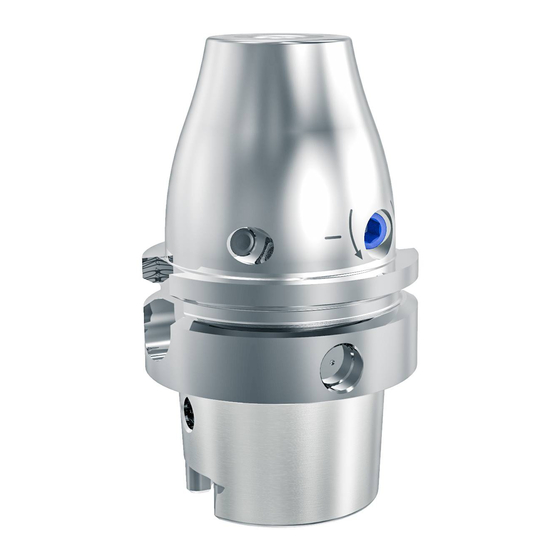
  • Seite 14 L L e e g g e e n n d d e e Anschlagschraube zur axialen Werkzeuglängeneinstel- lung Sicht von unten auf das Dehnspannfutter 4 4 . . 2 2 B B e e s s c c h h r r i i f f t t u u n n g g d d e e r r B B e e t t ä ä t t i i g g u u n n g g s s e e l l e e m m e e n n t t e e Beschriftung zur Prüfung der Spannkraft Montage- und Betriebsanleitung Montage- und Betriebsanleitung...
  • Seite 15 L L e e g g e e n n d d e e + + Werkzeug spannen (im Uhrzeigersinn) - - Werkzeug lösen (gegen Uhrzeigersinn) Drehrichtungsangabe zum Lösen und Spannen des Werkzeugs 4 4 . . 3 3 B B e e n n ö ö t t i i g g t t e e W W e e r r k k z z e e u u g g e e , , H H i i l l f f s s - - u u n n d d B B e e t t r r i i e e b b s s s s t t o o f f f f e e •...
  • Seite 16: Allgemeine Technische Daten

     Die Grenzbelastbarkeit der maschinenseitigen Schnittstelle nach z. B. VDMA 34181 beachten.  Treten Unregelmäßigkeiten während der Bedienung auf, das Dehnspannfutter aus Sicherheitsgründen nicht mehr ein- setzen und es zur Überprüfung oder zur Reparatur an MAPAL senden. • Allgemeine technische Daten •...
  • Seite 17 • Angabe zur Prüfung der Spannkraft (siehe Kapitel 4.2 und 4.5 • Richtwerte der maximalen Betriebsdrehzahlen von Dehnspannfutter mit HSK-Schnittstelle N N e e n n n n g g r r ö ö ß ß e e M M a a x x i i m m a a l l e e B B e e r r i i e e b b s s d d r r e e h h z z a a h h l l H H S S K K [ [ m m i i n n...
  • Seite 18 4 4 . . 5 5 P P r r ü ü f f u u n n g g d d e e r r S S p p a a n n n n k k r r a a f f t t Die Mindestumdrehungen werden auf dem Dehnspannfutter angegeben (siehe Kapitel 4.2 ) und stellen eine einfache und...
  • Seite 19 W W A A R R N N U U N N G G S S p p a a n n n n e e n n u u n n d d E E n n t t s s p p a a n n n n e e n n b b e e i i l l a a u u f f e e n n d d e e r r M M a a s s c c h h i i n n e e ! ! Durch das Spannen und Entspannen des Dehnspannfutters bei laufender Maschine können schwere Verletzungen des Bedieners verursacht werden.
  • Seite 20 Schieben Sie das Werkzeug mit dem Schaft voraus bis zur Anschlag- schraube in die Aufnahmebohrung des Dehnspannfutters. Werkzeug einschieben H H I I N N W W E E I I S S B B e e s s c c h h ä ä d d i i g g u u n n g g d d u u r r c c h h N N i i c c h h t t e e i i n n h h a a l l t t e e n n d d e e r r M M i i n n d d e e s s t t e e i i n n s s p p a a n n n n t t i i e e f f e e b b e e i i m m D D e e h h n n s s p p a a n n n n f f u u t t t t e e r r ! ! ...
  • Seite 21 I I N N F F O O R R M M A A T T I I O O N N Die Anschlagschraube zur axialen Werkzeuglängeneinstellung ist nicht gegen Herausfallen gesichert. Der angegebene Verstellbereich kann nicht überschritten werden. Die Betätigung der Anschlagschraube zur axialen Werkzeuglängen- einstellung ist beidseitig möglich.
  • Seite 22 I I N N F F O O R R M M A A T T I I O O N N Die Spannschraube ist gegen Herausfallen nicht gesichert! Achten Sie darauf, dass die Spannschraube schmutzfrei ist. Drehen Sie die Spannschraube mit Hilfe eines Innensechskantschlüssels Abb.
  • Seite 23 I I N N F F O O R R M M A A T T I I O O N N Die Spannschraube ist nicht gegen Herausfallen gesichert. Lösen Sie die Spannschraube mit U U m m d d r r e e h h u u n n g g e e n n mit Hilfe des pas- senden Innensechskantschlüssels mit Quergriff.
  • Seite 24 E E n n t t s s o o r r g g u u n n g g Nachdem das Gebrauchsende des Dehnspannfutters erreicht ist, muss das Dehnspannfutter einer umweltgerechten Entsor- gung zugeführt werden. Das Dehnspannfutter kann zur fachgerechten Entsorgung auch an MAPAL gesendet werden. Montage- und Betriebsanleitung...
  • Seite 26 T T a a b b l l e e o o f f c c o o n n t t e e n n t t s s P P u u r r p p o o s s e e o o f f t t h h e e i i n n s s t t a a l l l l a a t t i i o o n n a a n n d d o o p p e e r r a a t t i i n n g g i i n n s s t t r r u u c c t t i i o o n n s s ........................................2 2 7 7 C C o o n n t t a a c c t t .
  • Seite 27 The installation and operating instructions form an integral part of the hydraulic chuck and must be kept in the immediate vicinity of the hydraulic chuck where it is accessible to the personnel at all times. A basic precondition for safe working is compliance with all the safety precautions and instructions for working given in these installation and operating instruc- tions.
  • Seite 28 • The hydraulic chuck may only be used when observance of all the instructions given in this manual is assured. • Should a maximum rotational speed exist for the tool, it is not to be exceeded.
  • Seite 29 • The hydraulic chuck must not be heated on a shrink unit. It is not designed for the shrinking process and the associated temperatures. • The hydraulic chuck must not be used for workpiece clamping. • The hydraulic chuck must not be modified and used for other applications.
  • Seite 30  Observe the maximum load limit for the machine-side connection in accordance with e.g. VDMA 34181.  If irregularities occur during operation, do not use the hydraulic chuck further for safety reasons and send it to MAPAL for inspection or repair.
  • Seite 31 S S h h r r i i n n k k i i n n g g o o r r h h e e a a t t i i n n g g t t h h e e h h y y d d r r a a u u l l i i c c c c h h u u c c k k c c a a n n l l e e a a d d t t o o i i n n j j u u r r i i e e s s a a n n d d d d a a m m a a g g e e t t o o m m a a c c h h i i n n e e s s a a n n d d a a c c c c e e s s s s o o r r i i e e s s ! ! Shrinking or heating can cause the hydraulic chuck to become deformed or to burst explosively. Hot oil, oil vapours and metal slivers can then fly around uncontrolled and cause serious injuries to the operator and cause damage to machines and accessories.
  • Seite 32 C C l l a a m m p p i i n n g g a a n n d d u u n n c c l l a a m m p p i i n n g g w w i i t t h h r r u u n n n n i i n n g g m m a a c c h h i i n n e e ! ! Clamping and unclamping the hydraulic chuck with the machine running may result in serious injuries to the operator.
  • Seite 33 D D a a m m a a g g e e t t o o t t h h e e s s e e a a l l e e d d b b l l e e e e d d e e r r s s c c r r e e w w ! ! In the event of damage to the sealed bleeder screw, the hydraulic chuck is no longer functional and must be taken out of operation immediately.
  • Seite 34 S S h h r r i i n n k k i i n n g g o o r r h h e e a a t t i i n n g g t t h h e e h h y y d d r r a a u u l l i i c c c c h h u u c c k k c c a a n n l l e e a a d d t t o o i i n n j j u u r r i i e e s s a a n n d d d d a a m m a a g g e e t t o o m m a a c c h h i i n n e e s s a a n n d d a a c c c c e e s s s s o o r r i i e e s s ! ! Shrinking or heating can cause the hydraulic chuck to become deformed or to burst explosively. Hot oil, oil vapours and metal slivers can then fly around uncontrolled and cause serious injuries to the operator and cause damage to machines and accessories.
  • Seite 35 The hydraulic chuck bears this warning sign. Warning sign on the hydraulic chuck Position of prohibition symbol and warning sign on the hydraulic chuck Montage- und Betriebsanleitung Montage- und Betriebsanleitung Installation and Operating Instructions Installation and Operating Instructions...
  • Seite 36 L L e e g g e e n n d d Location bore Clamping screw Sealed bleeder screw | Projection length Individual components of the hydraulic chuck Montage- und Betriebsanleitung Montage- und Betriebsanleitung Installation and Operating Instructions Installation and Operating Instructions...
  • Seite 37 Stop screw for axial tool length adjustment View of the hydraulic chuck from below 4 4 . . 2 2 M M a a r r k k i i n n g g o o f f t t h h e e a a c c t t u u a a t t i i n n g g e e l l e e m m e e n n t t s s...
  • Seite 38 L L e e g g e e n n d d + + Clamp tool (in clockwise direction) - - Unclamp tool (in anticlockwise direction) Indication of the direction of rotation for clamping and unclamping the tool 4 4 . . 3 3 T T o o o o l l s s a a n n d d m m a a t t e e r r i i a a l l s s r r e e q q u u i i r r e e d d •...
  • Seite 39: General Technical Data

     Observe the maximum load limit for the machine-side connection in accordance with e.g. VDMA 34181.  If irregularities occur during operation, do not use the hydraulic chuck further for safety reasons and send it to MAPAL for inspection or repair.
  • Seite 40 • Estimated rotational speed limits for hydraulic chuck with HSK connection N N o o m m i i n n a a l l s s i i z z e e M M a a x x . . r r o o t t a a t t i i o o n n a a l l s s p p e e e e d d...
  • Seite 41 S S h h r r i i n n k k i i n n g g o o r r h h e e a a t t i i n n g g t t h h e e h h y y d d r r a a u u l l i i c c c c h h u u c c k k c c a a n n l l e e a a d d t t o o i i n n j j u u r r i i e e s s a a n n d d d d a a m m a a g g e e t t o o m m a a c c h h i i n n e e s s a a n n d d a a c c c c e e s s s s o o r r i i e e s s ! ! Shrinking or heating can cause the hydraulic chuck to become deformed or to burst explosively. Hot oil, oil vapours and metal slivers can then fly around uncontrolled and cause serious injuries to the operator and cause damage to machines and accessories.
  • Seite 42 C C l l a a m m p p i i n n g g a a n n d d u u n n c c l l a a m m p p i i n n g g w w i i t t h h r r u u n n n n i i n n g g m m a a c c h h i i n n e e ! ! Clamping and unclamping the hydraulic chuck with the machine running may result in serious injuries to the operator.
  • Seite 43 Push the tool, shank first, to the stop screw in the location bore in the hydraulic chuck. Inserting tool N N O O T T I I C C E E D D a a m m a a g g e e f f r r o o m m f f a a i i l l u u r r e e t t o o o o b b s s e e r r v v e e t t h h e e m m i i n n i i m m u u m m c c l l a a m m p p i i n n g g d d e e p p t t h h i i n n t t h h e e h h y y d d r r a a u u l l i i c c c c h h u u c c k k ! ! ...
  • Seite 44 Actuation of the stop screw for axial tool length adjustment is pos- sible from both sides. Adjust the hydraulic chuck to the tool length by turning the stop screw for the axial tool length adjustment using an appropriate hex-wrench with T-handle.
  • Seite 45 U U n n c c l l a a m m p p i i n n g g a a t t e e x x c c e e s s s s i i v v e e c c l l a a m m p p i i n n g g c c h h u u c c k k t t e e m m p p e e r r a a t t u u r r e e s s ! ! Unclamping at excessive clamping chuck temperatures can cause parts of the hydraulic chuck to fly off uncontrolled, al- lowing hot oil to escape.
  • Seite 46 Loosen the clamping screw with 3 3 to 7 7 t t u u r r n n s s using an appropriate hex- wrench with T-handle. Loosening clamping screw Remove the tool from the location bore of the hydraulic chuck. Removing tool Montage- und Betriebsanleitung...
  • Seite 47 D D i i s s p p o o s s a a l l Once the hydraulic chuck reaches the end of its service life, it must be disposed of with due care for the protection of the environment.
  • Seite 48 © MAPAL Präzisionswerkzeuge Dr. Kress KG Kein Teil dieser Anleitung darf in irgendeiner Form (Druck, Fotokopie, Mikrofilm oder einem anderen Verfahren) ohne schriftliche Zustimmung der Firma MAPAL Präzisionswerkzeuge Dr. Kress KG, Aalen, reproduziert oder unter Verwendung elektronischer Systeme verarbeitet werden.

Diese Anleitung auch für:

Hydro dream chuck 4,5