GF CONTAIN-IT Plus Bedienungsanleitung
Vorschau ausblenden
Andere Handbücher für CONTAIN-IT Plus:
- Bedienungsanleitung (56 Seiten) ,
- Bedienungsanleitung (24 Seiten)

Verwandte Anleitungen für GF CONTAIN-IT Plus


Inhaltszusammenfassung für GF CONTAIN-IT Plus
- Seite 1 GF Piping Systems Instruction manual Bedienungsanleitung CONTAIN-IT Plus Ball Valve Type 546 CONTAIN-IT Plus Kugelhahn Typ 546...
- Seite 2 Betriebsanleitung Inhaltsverzeichnis Deutsch CONTAIN-IT Plus Kugelhahn Typ 546…………………………………………… 3 English CONTAIN-IT Plus Ball Valve Type 546 …….……………………………….. 27...
-
Seite 3: Inhaltsverzeichnis
Bestimmungsgemässe Verwendung Sicherheitshinweise Transport und Lagerung Aufbau und Funktion Aufbau Funktion Installation Vorbereiten Installation Druckprüfung vorbereiten Druckprüfung durchführen Montage CONTAIN-IT Plus Kugelhahn Typ 546 Wartung Ausbau Einbau Nachrüstung von Antrieben Störungsbehebung Ersatzteilliste Zapfen PE-Anschlussstutzen Einschraubteil/ Einlegeteil Kugelhahn Typ 546, Zentralteil 10 Entsorgung 11 EG-Konformitätserklärung... -
Seite 4: Originalbetriebsanleitung
Betriebsanleitung Originalbetriebsanleitung Originalbetriebsanleitung Betriebsanleitung beachten Die Betriebsanleitung ist Teil des Produkts und ein wichtiger Baustein im Sicherheitskonzept. Betriebsanleitung lesen und befolgen. Betriebsanleitung stets am Produkt verfügbar halten. Betriebsanleitung an alle nachfolgenden Verwender des Produkts weitergeben. Zu diesem Dokument Warnhinweise In dieser Anleitung werden Warnhinweise verwendet, um Sie vor Tod, Verletzungen oder vor Sachschäden zu warnen. -
Seite 5: Weitere Symbole Und Auszeichnungen
Mitgeltende Dokumente Georg Fischer Planungsgrundlagen Industrie Bedienungsanleitung Kugelhahn Typ 546 (GFDO 5684) Diese Unterlagen sind über die Vertretung von GF Piping Systems oder unter www.gfps.com erhältlich. Sicherheit und Verantwortung Bestimmungsgemässe Verwendung Der CONTAIN-IT Plus Kugelhahn Typ 546 ist ausschliesslich dazu bestimmt nach... -
Seite 6: Transport Und Lagerung
Betriebsanleitung Transport und Lagerung Personal regelmässig in allen zutreffenden Fragen der örtlich geltenden Vorschriften für Arbeitssicherheit, Umweltschutz vor allem für druckführende Rohrleitungen unterweisen. Betriebsanleitung und die darin enthaltenen Hinweise kennen, verstehen und beachten. Bei jedem Ein- bzw. Ausbau der Doppelrohr-Armatur die Einbaubedingungen sowie die Sicherheits- und Warnbedingungen der mitgeltenden Betriebsanleitung für den Kugelhahn Typ 546 beachten. -
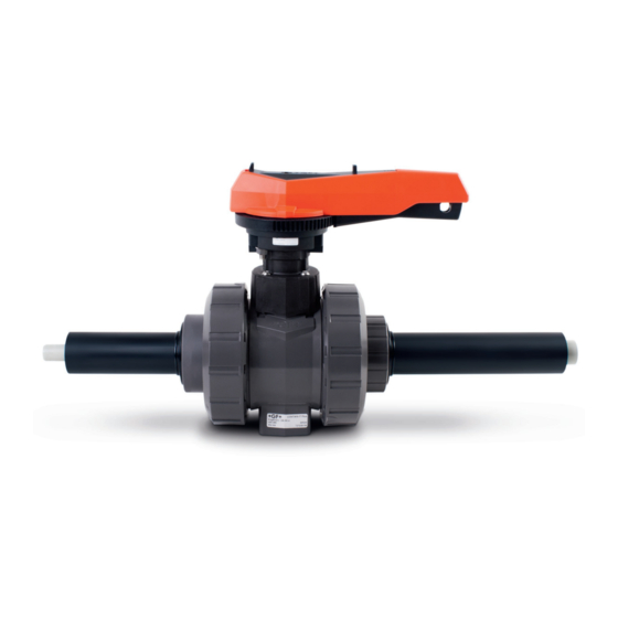
Seite 7: Aufbau Und Funktion
Aufbau und Funktion Betriebsanleitung Aufbau und Funktion Aufbau Abb. 1 Durchgangsbohrung für die Zapfen Leckageüberwachung der Innenleitung Überwurfmutter Schutzgehäuse Distanzhalter Einlegteil Abstützungen PE Schutzgehäuse Einschraubteil Anschluss für ½ Zoll O-Ringe zum Einlegteil / Leckageüberwachung oder PVC- Einschraubteil U ½ Zoll Stopfen Kugelhahn Typ 546 (Zentralteil) O-Ringe zum Zapfen Überwurfmutter Kugelhahn Typ... -
Seite 8: Funktion
Doppelrohr-Armaturen von GF Piping Systems werden als einbaufertige Systemeinheit geliefert und analog einem Doppelrohrfitting verarbeitet. Das Prinzip der Doppelrohr-Verbindungstechnik von GF Piping Systems basiert darauf, dass zuerst die Innenleitung nach der von Ihnen gewählten Verbindungstechnik verbunden wird. Folgende Verbindungstechniken und... -
Seite 9: Installation
Installation Betriebsanleitung ACHTUNG Sachschaden beim Einbau des Kugelhahns! Inkorrekter Einbau kann zu Problemen bei den Toleranzen führen. Sicherstellen, dass die Verbindung der Rohrenden mit den anderen Rohrleitungsabschnitten erst nach dem Zusammenbau des Kugelhahns erfolgt. Installation WARNUNG Verletzungsgefahr und/ oder Sachschaden beim Ausbau des Handhebels! Durch den Aufbau von Innendruck kann der Austritt des Zapfens zu Verletzungen/ Beschädigungen führen. - Seite 10 Betriebsanleitung Installation 3. Sicherstellen, dass Druckklasse, Anschlussart und Anschlussabmessungen den Einsatzbedingungen entsprechen. 4. Kugelhahn erst unmittelbar vor Einbau aus Originalverpackung nehmen. 5. Sicherstellen, dass die Kugelhahnstellung auf „AUF“ ist, siehe Abb. 1 6. Innenrohr des Kugelhahns mit Innenrohr der Doppelrohrleitung verbinden. 7.
- Seite 11 Installation Betriebsanleitung Maximale Einschraubtiefe der Schrauben in den Kugelhahn: 10/15 20/25 32/40 Schraube Einschraubtiefe H (mm) ACHTUNG Wird bei Temperaturwechseln die Wärmeausdehnung verhindert, treten Längs- bzw. Biegekräfte auf! Um die Funktionsweise der Armatur nicht zu beeinträchtigen: Sicherstellen, dass Kräfte durch geeignete Festpunkte vor bzw. hinter Armatur aufgenommen werden.
-
Seite 12: Druckprüfung Vorbereiten
Betriebsanleitung Installation Druckprüfung vorbereiten 1. Sicherstellen, dass der rote Handhebel parallel zur Hauptleitung steht. Abbildung 1 2. Muttern am Handhebel lösen. 3. Handhebel entfernen. Abbildung 2 4. Überwurfmuttern des Schutzgehäuses beidseitig lösen. 5. Überwurfmuttern und Einlegteil zur Seite schieben. Abbildung 3 6. -
Seite 13: Druckprüfung Durchführen
Installation Betriebsanleitung 9. Gehäuse zur Seite des Einlegteils schieben. Der Kugelhahn ist nun zugänglich Abbildung 6 Druckprüfung durchführen WARNUNG Verletzungsgefahr und/ oder Sachschaden beim Drucktest! Der Einsatz von gefährliche Medien zum Drucktest kann ein Risiko für die Anlage bedeuten und im Falle einer Leckage Schäden oder Verletzungen zur Folge haben. -
Seite 14: Montage Contain-It Plus Kugelhahn Typ 546
Betriebsanleitung Installation Montage CONTAIN-IT Plus Kugelhahn Typ 546 1. Gehäuse über den Kugelhahn schieben. Abbildung 7 2. Zapfen durch die Öffnung des Gehäuses stecken. 3. Dabei die richtige Position des Zapfens beachten, siehe Kontur des Zapfens und des Kugelhahns. Abbildung 8 Abbildung 9 4. - Seite 15 Installation Betriebsanleitung 5. Einschraubteil in das Schutzgehäuse (Linksgewinde!) schrauben und mit dem Zapfenschlüssel anziehen. Abbildung 11 6. Einlegteil positionieren und Überwurfmuttern auf beiden Seiten verschrauben. Überwurfmutter mit einem geeigneten Schlüssel anziehen. Abbildung 12 7. Handhebel auf das Gehäuse montieren. Abbildung 13...
-
Seite 16: Demontage
Wartung VORSICHT Materialschaden und/oder Verletzungsgefahr! Bei Austausch dürfen ausschliesslich die für die Armatur vorgesehenen Original-Ersatzteile von GF Piping Systems verwendet werden. Ersatzteile mit den Angaben auf dem Typenschild bestellen. Keine Schmiermittel auf Mineralölbasis oder Vaseline (Petrolatum) verwenden. Für lackstörungsfreie Kugelhähne spezielle Herstellerhinweise beachten. -
Seite 17: Ausbau
Polyglykolbasis fetten Wir empfehlen beim Wiedereinbau des Kugelhahns generell neue Dichtungselemente zu verwenden. 2. CONTAIN-IT Plus Kugelhahn Typ 546 in die Innenleitung einsetzen. Dabei beachten, dass sich der Kugelhahn in „offener“ Stellung befindet. 3. Druckprüfung, siehe Kapitel Druckprüfung durchführen 4. -
Seite 18: Nachrüstung Von Antrieben
Betriebsanleitung Nachrüstung von Antrieben Nachrüstung von Antrieben Der CONTAIN-IT Plus Kugelhahn Typ 546 kann mit den Antrieben EA11, EA21 und PA21 gemäss nachfolgender Beschreibung aufgerüstet werden. Bitte beachten Sie jeweils auch die Anleitungen der jeweiligen Antriebe. Zur Aufrüstung eines Antriebes benötigen Sie das Adapter Set 700 238 796. Dieses... - Seite 19 Nachrüstung von Antrieben Betriebsanleitung 5. Adapterplatte mit vier Senkschrauben an den Antrieb montieren. Abbildung 17 6. Reduzierhülse auf den Zapfen des Kugelhahns setzen. Abbildung 18 7. Antrieb mit der Adapterplatte auf das Anschlussmodul des Kugelhahns montieren. Abbildung 19...
-
Seite 20: Störungsbehebung
Betriebsanleitung Störungsbehebung 8. Kugelhahns und Antrieb sind nun betriebsbereit. Abbildung 20 Störungsbehebung Störung Mögliche Ursache Störungsbehebung Rohrleitung und/oder Rohrleitungskräfte Abstützung der Rohrleitung Kugelhahn verformen sind zu hoch verbessern sich bzw. dehnen sich Vorzeitiger Verschleiss Werkstoff sind nicht Geeignete Werkstoffe des Kugelhahns oder genügend beständig auswählen, siehe... - Seite 21 Störungsbehebung Betriebsanleitung Mediumsleckage an Überwurfmutter Überwurfmutter nachziehen. Verbindung zwischen nicht korrekt Ventilkörper und angezogen Überwurfmutter Leckage im Sitz / Vorspannung nicht Überwurfmutter korrekt Durchgangsleckage korrekt anziehen. Armatur schwergängig Verschleiss von Funktionsteile wechseln. Kugel und Zapfen Leckage des Steuer- Verschleiss der ...
-
Seite 22: Ersatzteilliste
Betriebsanleitung Ersatzteilliste 10 Ersatzteilliste 10.1 Zapfen siehe Kapitel Aufbau, Pos. 3 Dimension Artikelnummer Menge Dimension Beschreibung Kugelhahn d20/50 – d32/50 748 410 103 3.54mm x 29.75mm O-Ring EPDM 749 410 103 3.54mm x 29.75mm O-Ring FPM d40/75 – d63/110 748 410 027 3.54mm x 37.69mm O-Ring EPDM 749 410 027... -
Seite 23: Kugelhahn Typ 546, Zentralteil
Ersatzteilliste Betriebsanleitung 10.4 Kugelhahn Typ 546, Zentralteil siehe Kapitel Aufbau, Pos. 9 EPDM Dichtungsset: Dimension Kugelhahn Artikelnummer Beschreibung d20/50 161 486 400 Dichtungsset EPDM bestehend aus: d25/50 161 486 401 2 Hinterlagedichtungen 1 Gehäusedichtung d32/63 161 486 402 2 Anschlussdichtungen d40/75 161 486 403 2 Zapfen O-Ring Dichtungen... -
Seite 24: Entsorgung
Vorschriften entsorgen. Sicherheitsdatenblatt konsultieren. eventuelle Medienrückstände im Produkt neutralisieren. Werkstoffe (Kunststoffe, Metalle, usw.) trennen und diese nach den örtlichen Vorschriften entsorgen. Bei Fragen bezüglich der Entsorgung des Produkts wenden Sie sich an Ihre nationale Vertretung von GF Piping Systems. -
Seite 25: Eg-Konformitätserklärung
EG-Konformitätserklärung Betriebsanleitung 12 EG-Konformitätserklärung EG-Druckgeräterichtlinie 97/23 EG Der Hersteller Georg Fischer Rohrleitungssysteme AG, 8201 Schaffhausen (Schweiz) erklärt, dass die Kugelhähne des Typs 546 gemäss der harmonisierten Bauart-Norm EN ISO 16135 1. Druckhaltende Ausrüstungsteile im Sinne der EG-Druckgeräterichtlinie 97/23 EG sind und solchen Anforderungen dieser Richtlinie entsprechen, die für Armaturen zutreffen.