Werbung
Verfügbare Sprachen
Verfügbare Sprachen
Quicklinks
85032-536-71
Combi.jet 16848-CJ
Typical Construction: Microsart
1. Setting up the Combi.jet System
Assemble and set up the e.jet transfer pump according to the
operating instructions and equip it with tubing to drain off
the filtrate (When doing so, pay attention to the flow direction
indicated by the arrow on the black pump head!).
Now connect the outlet of Combi.jet by simply inserting the
white coupling into the hose barb on the Microsart
(166MP-3).
2. Filtration
Stainless steel stopcocks on the lower parts allow the vacuum to
be switched on and off independently for each individual filtration
adapter, thereby minimizing the risk of secondary contamination.
The stainless steel supports serving as filter supports ensure that
residue or microbes are distributed evenly across the membrane
filter surface.
2.1 All parts of the system that come into contact with the sample
and filter membrane should be sterile. A variety of options are
available, depending on the material:
a) Autoclaving (stainless steel, glass and polycarbonates):
Assemble the units together so that a filter membrane is
securely clamped between the lower part and the funnel.
Note that the filter should not be clamped so firmly that steam
is prevented from entering into the clamp.
Setting the Three-way Stopcock to "12 O'clock". Cover the
inlets and outlets with aluminum foil and autoclave in accordance
with the specifications for the system components. After steriliza-
tion, assemble the system securely back together and connect it
to the other system components.
Setting the Three-way Stopcock to "9 O'clock".
a) Flaming (stainless steel only): This saves long waits in between
the individual filtration runs and will be described in detail in
the following.
2.2 Clean your laboratory bench and disinfect it with alcohol or
a commercially available disinfectant.
2.3 Set up your sterile culture media, e.g. nutrient pad sets in
Petri dishes or, alternately, agar in Petri dishes. Wet the nutrient
pad sets with 3.0–3.5 ml of sterile distilled or demineralized
water. For this purpose, we recommend our dosing syringe
(16685-2) with pre-installed sterile Minisart
2.4 Place a Bunsen burner and a glass with some alcohol with
a forceps in it next to the autoclaved filtration unit.
a) Place the sterile-packaged membrane filters in easily
accessible proximity.
b) Switch on the e.jet transfer pump and remove the funnel.
c) Flame the stainless steel support with the Bunsen burner.
To do so, open the stopcock ("6 o'clock") and use a vacuum to
draw the flame through the support. Afterwards, re-close the
stopcock ("9 o'clock").
d) Place the funnel back on to the lower part.
e) To speed up the cooling down of the filter unit and simplify
membrane filter insertion, rinse the unit with sterile water
(e.g. using a dosing syringe and an attached sterile Minisart
To suction off the water, open the stopcock ("6 o'clock") and
close again ("9 o'clock").
f) Sterilize the forceps briefly over the flame and take the sterile
membrane filter (if applicable, with the yellow guard) out of its
packaging. Using one hand, remove the funnel from the lower
part of the unit and place the membrane filter (with the mesh
and/or yellow guard pointing up) in the middle of the support.
g) If the membrane filter is equipped with a yellow guard,
remove it before assembling the unit onto the upper part or
funnel. Place the funnel back into the lower part of the unit.
2.5 Pour the sample to be tested into the funnel. For sample vol-
umes < 5 ml, charge with 10 to 20 ml sterile water or physio-
logical saline. For suctioning, reopen the stopcock ("6 o'clock"),
switch on the e.jet transfer pump and switch it off again at
the end of the filtration run or close the stopcock afterwards
("9 o'clock").
2.6 Remove the funnel and extract the membrane filter using
a flamed forceps.
Settings on the three-way stopcocks
Stopcock Position
OPEN
"6 o'clock"
Filtration
The full vacuum draws the sample
through the membrane filter.
The ventilation filter is separated.
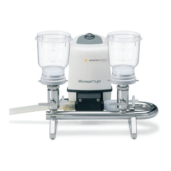
®
e.jet pump (166MP-4) with Combi.jet manifold (16848-CJ), stainless steel base supports (1ZU---0002)
®
and Microsart
@filter 250 (16D01--25-H6--BK).
®
e.jet pump
®
(17597-K).
Stopcock Position
VENTING
"9 o'clock"
After Filtration
The vacuum between stopcock and
membrane filter is released in a
sterile and particulate-free state.
This reliably prevents any secondary
contamination entering the lower
side of the filter.
2.7 Place the membrane filter on a nutrient pad set or on an agar
culture medium and subsequently incubate in a laboratory incu-
bator. When placing the membrane filter on the nutrient pad
set, make sure to avoid the inclusion of any air bubbles.
The membrane filter can additionally be used for gravimetric,
optical, chemical or other analyses.
2.8 Before storing the units, please rinse them with at least 70%
alcohol and allow the system components to air-dry.
2.9 Later analysis of the colony count can be simplified by mesh
embossed on the membrane.
Note: Prefiltration
Samples that have a high content of dirt and/or insoluble solids
should be prefiltered for the detection of bacteria. The prefiltration
adapter made of stainless steel (16807) allows prefiltration to be
conducted together with the actual membrane filtration in one work
session. Attach the adapter between the stainless steel funnel and
the lower part, fill to the brim with sterile water (this is to avoid
that any air inclusions impair filtration) and install a bacteriological
prefilter 11301-050 (8 μm pore size). Any coarse particles contained
in the sample to be tested will be retained by this prefilter which
takes a load off the membrane filter lying on the stainless steel
support and allows the colonies to grow without the adverse effects
of deposits.
The prefiltration adapter can similarly be flamed.
3. Cleaning and Care of Stainless Steel Equipment
To ensure a long service-life and functionality, it is necessary to
clean the units prior to first use and after each filtration.
To do so, proceed as follows:
1. Unscrew the white coupling from the stainless steel arch.
2. Clean all parts with warm water and gentle commercially
available laboratory cleaning agents (for metal, glass, plastic)
and soft brushes.
3. Rinse off the parts with hot water and afterwards with distilled
water. Additional flushing with 70% alcohol accelerates the
drying process.
4. Dry the parts in the drying oven. For drying, please use lint-free
towels that do not release fibers into the unit.
4. Care of the Stainless Steel Three-way Stopcock
If the stopcock turns out to be difficult to operate, it should be
removed, cleaned, dried and greased (e.g. with heavy-weight high-
vacuum grease).
To remove the stopcock, please proceed as follows:
4.1 First, remove the knurled nut and the washer on the rear
of the stopcock.
4.2 Now, you can pull out the stopcock.
If you have removed the stopcocks from several filtration
devices, when reinstalling them, it is imperative that you make
sure that each stopcock is placed back the designated ground
conical joint it was removed from. Each joint was ground to
achieve an exactly fit, i.e. lipped to high-precision.
5. Three-way Stopcock Positions
®
The Combisart
vacuum filter holder system features ultra-high
flexibility.
For the first time ever, Sartorius Stedim Biotech offers a system
where all funnel models can be adapted to all lower parts.
®
).
The user always has a flexible choice of options when it comes to
selecting materials, the number of units and the performance time.
The multi-branch systems (3-branch or 6-branch manifolds) in
particular feature ultra-simple handling:
–
Each individual filter station can be autoclaved separately from
the manifold, and thus saves autoclave capacity.
–
The supernatant in clogged membranes can be easily discarded
by simply throwing away the filter station.
–
All funnels can be positioned variably, depending on whether
the investigator is right- or left-handed.
®
With the Minisart
SRP syringe filters that are inserted into the side
of the three-way stopcocks, you are guaranteed reliable results.
These syringe filters protect the lower side of the filter against
possible contamination with ambient microorganisms and particles.
6. Specifications:
Material:
Base support for membrane filter diameter 47 mm
Max. operating pressure: Vacuum max. 2 bar overpressure
Autoclaving:
Dry heat:
Stopcock Position
END
"3 o'clock"
After the Filtration Campaign
The residual vacuum between
pump and stopcock is released via
the sterile filter.
Stainless steel round arch:
Material 1.4301 (B.S. 304S31/AlSl 304)
Coupling: PVDF
Max. 134°C, 30 min
Max. 180°C, 30 min
Stopcock Position
AUTOCLAVING
"12 o'clock"
For Autoclaving
To reliably achieve
sterilization, allow t
he steam to flow
unimpaired through
all openings.
Werbung

Verwandte Anleitungen für Sartorius Stedim Biotech Combi.jet 16848-CJ


Inhaltszusammenfassung für Sartorius Stedim Biotech Combi.jet 16848-CJ
- Seite 1 To speed up the cooling down of the filter unit and simplify For the first time ever, Sartorius Stedim Biotech offers a system membrane filter insertion, rinse the unit with sterile water where all funnel models can be adapted to all lower parts.
- Seite 2 Minisart ® ). Zum Absaugen des Was- Erstmals hat Sartorius Stedim Biotech ein System bei dem sich alle sers den Hahn öffnen („6 Uhr“) und wieder schließen („9 Uhr“). Trichter-Modelle auf alle Unterteile adaptieren lassen. f) Sterilisieren Sie die Pinzette kurz in der Flamme und entnehmen...