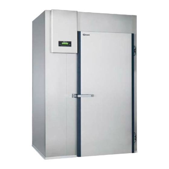
4. Installing the control panel and door switch..........46 Technical data KPS 120................53 Technical data KPS 180................54 Wiringdiagrams .................... 55 Wiring diagram KPS 120/180 with defrosting..........55 Piping diagram KPS 120/180 ............... 59 Inhalt Technische Voraussetzungen..............60 1.
4. Nødvendig elektrisk tilslutning til blæstkøleren. (Se venligst tekniske data). Montering af rum med tilhørende fordampersektion Forløb: 1. Opstilling af rum KPS 120/180 2. Klargøring af fordampersektion til montage 3. Montering af fordampersektion, rør og ledninger 4. Montering af el-skab og dørkontakt...
1. Opstilling af Rum KPS 120/180 Vigtigt! Vær opmærksom på hvordan fordamperen skal monteres inden rummet sættes op. Gennemgå derfor vejledningen grundigt inden montagearbejdet påbegyndes. Rummet til blæstkøleren består af moduler som vist på illustration 2: 5 stk. vægmoduler 1 stk. dørmodul 1 stk.
Seite 5
4. Afslut med at lægge loftet på plads. Loftet kan monteres før væggen med dørmodulet, hvis pladsforhold over rummet gør, at loftet ikke kan løftes over vægmodulerne. 765041176...
Seite 6
Eksplosionstegning Illustration 2. Placering af U-profiler Illustration 3 765041176...
Seite 7
Udfræsning i u-profil til fordamperstativ (uden gulv) Udfræsning ind til niveau vægmodul Illustration 4 Vægmodul placeret i U-profilen (uden gulv) Illustration 5. Vægmodul placeret i U-profilen (med gulv) Illustration 6. 765041176...
Seite 8
Udsparing i gulv ved planforsænkning. Illustration 8 Illustration 7 Tilpasning af U-profil (kun ved planforsænkning i gulv) Illustration 9 Montage Illustration 10 765041176...
2. Klargøring af fordampersektion til montage Vigtigt! 1. Ved levering er løsdele og el-skab placeret mellem fordamperne i fordampersektionen. Disse dele skal fjernes før montagestart. 2. Fordamperen er påfyldt 10 bar nitrogentryk. Schraderventil er monteret på fordamperen. OBS! Kontroller trykket, inden nitrogenet afblæses med forsigtighed! 3.
3. Montering af fordampersektion, rør og ledninger. Fordamperen monteres med 4 fastgørelser til rummet. Konstruktionen af fordamperen gør at der skal være 100mm plads på begge sider. Illustration 10 og 11 på de følgende sider viser hvordan fordampersektionen skal placeres i rummet og hvordan den skal monteres. •...
Seite 11
Montagehuller Illustration 11. 765041176...
Seite 12
Fastgørelse i vægmodul A-A ( 1 : 5 ) M10 rustfri møtrik. Nylon gevindstang. Modulmøtrik. OBS! Vær meget opmærksom på hvordan fordamperen skal monteres inden rummet sættes op. Gevindstykkerne er gennemgående Gulv Illustration 12. 765041176...
Seite 13
Mulighed for Mulighed for gennemføring væskeledning gennemføring sugeledning Ledningsgennemføring, ventilatorer, følere mv. Ledningsgennemføring, Varemlegemer. Placering Termoventil Placering Temperaturføler Placering Spydføler Placering Fordamperføler Gulv Placering Afløb fra drypbakke Illustration 13. 765041176...
Seite 14
Tilslutning af rør til køleanlæg Mulighed 1: Loft Op gennem taget Mulighed 2: Ud gennem væggen Gulv Illustration 765041176...
4. Montage af el-skab og El-skabet monteres på væggen ved siden af døren. Toppen af skabet placeres så den er min. 80mm under loftet på rummet jævnfør illustration 20+21. Ledningerne føres fra fordamperen og ud til el-skabet gennem et hul i modulvæggen.
Seite 19
7. Monter ledningerne i klemmerækken som angivet på ledningsdiagrammerne. 765041176...
Seite 20
Skabelon til opmærkning af huller Placeres i niveau med rummets top og dørens side Illustration 18. 765041176...
Seite 21
Placering hul til ledningsgennemføring i modulvæg Ø45 Illustration 19 765041176...
Seite 22
Placering el-skab Illustration 20 765041176...
Seite 23
Placering el-skab Illustration 21 Printeren (option) er en real-time printer til udskrift/dokumentation af temperaturforløb under køleprocesser. Printeren bruger standard termisk bonpapir str. 58xø30mm (max), som kan købes hos forhandlere af kontorartikler. 765041176...
Tekniske data KPS 120 KPS 120 CF KPS 120 SF Evaporator. Regulation range `-35 to +20 C `-35 to +20 C Refrigerant R 404 A R 404 A Pipe liquid 1/2" 1/2" Pipe gas 7/8" 7/8" Ref. Capacity at -10 8400 watt Ref.
Tekniske data KPS 180 KPS 180 CF KPS 180 SF Evaporator. Regulation range `-35 to +20 C `-35 to +20 C Refrigerant R 404 A R 404 A Pipe liquid 5/8" 5/8" Pipe gas 1 1/8" 1 1/8" Ref. Capacity at -10 10700 watt Ref.
4. Electrical connection of the blast chiller. (See technical data). Mounting of room with evaporator section Sequence: 1. Installation of room KPS 120/180 2. Preparation of evaporator section for installation 3. Installation of evaporator section, piping and wiring 4. Installation of control panel and door switch...
1. Installation of room KPS 120/180 Important! Be aware how the evaporator is mounted before installing the room. Please read the instructions carefully before starting the installation. The room consist of modules as shown in illustration 2: 5 wall modules...
Seite 34
Exploded view Illustration 2. Placement of U-profiles Illustration 3. 765041176...
Seite 35
Gaps for evaporator rack milled into the U-profile (without floor) Mill into level with wall panel. Illustration 4 Wall module placed in the U-profile (without floor) Illustration 5. Wall module placed in the U-profile (with floor) 765041176 Illustration 6.
2. Preparation of the evaporator section for installation. Important! 1. On delivery the loose parts and the control panel are placed inside the evaporator section. These parts must be removed before starting the installation. 2. The evaporator is filled with Nitrogen at 10 bars. A scrader valve is installed at the evaporator.
3. Installation of evaporator section, piping and wiring. The evaporator is installed with 4 attachments to the room. The evaporator is designed so that there must be 100 mm free space at each side. Illustration 10 and 11 on the following pages show the placement and installation of the evaporator.
Seite 39
Attachment holes Control panel Holes for installation of evaporator in wall module. Ø11 mm through holes Holes for mounting junction box Max Ø3mm Blast chiller seen from above Junction box model CF Junction box model SF Illustration 11. 765041176...
Seite 40
Fastening into wall module A-A ( 1 : 5 ) M10 stainless nut Threaded nylon bolt Module nut Be aware how the evaporator is to be placed before installing the room. The threaded bolts are through going. Floor Illustration 12. 765041176...
Seite 41
Lead-in for suction pipe Lead-in for liquid pipe Lead-in for wiring (fans, sensors, etc.) Lead-in for wiring Heating elements Location of thermostatic valve Location of temperature sensor Location of probe sensor Location of evaporator sensor Floor Location of drain Illustration 13. 765041176...
Seite 42
Refrigeration system piping connections Option 1: Ceiling through the ceiling Option 2: Through the wall Floor Illustration 14. 765041176...
Seite 43
Drain option 1 Drain outlet at right side. Pipe dimension: Ø32 mm Illustration 15. 765041176...
Seite 44
Afløbsalternativ 2. Drain option 2 Afløbet føres bagud Drain outlet to the rear of i forhold til fordamperen. the evaporator. Pipe dimension: Ø32 mm Størrelse på rør Ø32. Illustration 16. 765041176...
Seite 45
Drain option 3 Drain outlet at left side. Pipe dimension: Ø32 mm Illustration 17. 765041176...
4. Installing the control panel and door switch The control panel is to be installed at the wall module beside the door. The top of the control panel must be placed 80 mm above the ceiling of the room according to illustration 20+21. The wiring is to be lead from the evaporator out through the wall module and directly into the control panel.
Seite 47
and out through a drilled hole in back- or side wall nearest the wall outlet. 7. Install the wires in the terminal board as shown in the diagrams. 765041176...
Seite 48
Template for marking where to drill To be placed level with the top of the room and the side of the door Illustration 18. 765041176...
Seite 49
Position of holes for wire lead-in. Ø45 Illustration 19 765041176...
Seite 50
Position of the control panel Blast chiller seen from entrance side Door Illustration 20 765041176...
Seite 51
Position of the control panel Blast chiller seen from entrance side With printer (option) Door Illustration 21 The Printer (option) is a real-time printer for printing/dokumentation of temperature changes during chilling processes. The printer uses standard cash machine thermal paper size 58xØ30mm (max). Refills can be bought at the local dealer of stationery and office supplies.
Seite 52
Control panel. Illustration 22. 765041176...
Technical data KPS 120 KPS 120 CF KPS 120 SF Evaporator. Regulation range -35 to +20 C -35 to +20 C Refrigerant R 404 A R 404 A Pipe liquid 1/2" 1/2" Pipe gas 7/8" 7/8" Ref. Capacity at -10 8400 watt Ref.
Technical data KPS 180 KPS 180 CF KPS 180 SF Evaporator. Regulation range -35 to +20 C -35 to +20 C Refrigerant R 404 A R 404 A Pipe liquid 5/8" 5/8" Pipe gas 1 1/8" 1 1/8" Ref. Capacity at -10 10700 watt Ref.
4. Es ist ein elektrischer Anschluss erforderlich (siehe technische Daten). Montage der Kühlzelle und der Verdampfersektion 1. Aufstellen der Kühlzelle KPS 120/180 2. Vorbereitung der Verdampfersektion für die Montage 3. Montage der Verdampfersektion und der Rohrleitungen 4. Montage der Schalttafel mit Türkontaktschalter...
1. Aufstellen der Kühlzelle KPS 120/180 Achtung! Verschaffen Sie sich vor Beginn der Aufstellung der Kühlzelle Klarheit darüber, wie die Verdampfersektion montiert werden soll. Arbeiten Sie hierzu die Montageanleitung sorgfältig durch. Die Kühlzelle besteht aus einzelnen Elementen, s. Abbildung 2: 5 Stk.
Seite 62
4. Zum Schluß wird die Decke der Zelle aufgelegt. Die Decke kann vor der Montage des Türelementes erfolgen, wenn die Platzverhältnisse es nicht erlauben, die Decke über die Wandelement zu heben. Explosionszeichnung Abbildung 2 Anordnung der U-Profile Abbildung 3 765041176...
Seite 63
Aussparungen für das Verdampferstativ im U-Profil (ohne Boden): Aussparung bis zur Linie der späteren Wand- innenseite Abbildung 4 Aufstellen der Wandelemente im U-Profil (Montage ohne Boden) Abbildung 5. Aufstellen der Wandelemente im U-Profil (Montage mit Boden) Abbildung 6. 765041176...
Seite 64
Ausparung im Fußboden bei versenktem Aufbau Abbildung 7 Abbildung 8 Anpassung des U-Profils bei versenktem Aufbau Abbildung 9 Montage mit umlaufender Fuge (Aussenseite): Abbildung 10 765041176...
2. Vorbereitung der Verdampfersektion für die Montage Wichtig ! 1. Bei der Lieferung sind die Schalttafel und Kleinteile zwischen den Verdampfern in der Verdampfersektion verpackt. Diese Teile müssen vor Beginn der Montage entfernt werden. 2. Der Verdampfer ist mit Stickstoff bei einem Druck von 10 bar befüllt. Ein Schraderventil ist am Verdampfer montiert.
3. Montage der Verdampfersektion, Rohre und elektrischen Leitungen Der Verdampfer wird an vier Punkten an der Wand befestigt. Konstruktions- bedingt müssen auf jeder Seite der Verdampfersektion 100 mm freier Raum bleiben. Abbildungen 11 und 12 zeigen, wie der Verdampfer positioniert und montiert wird.
Seite 67
Montagelöcher: Schalttafel Durchgehende Löcher zur Montage Verdampfersektion, Ø11 mm Montagelöcher für den Abzweigkasten, max Ø 3 mm. Kühlzelle, Ansicht von oben Abzweigkasten Modell CF Abzweigkasten Modell SF Abbildung 11. 765041176...
Seite 68
Befestigung der Verdampfersektion im Wandelement Abbildung 12. 765041176...
Seite 69
Leitungsdurchführungen, Montagepunkte Abbildung 13. 765041176...
Anschluss der Kältemittelleitungen Abbildung 14. 765041176...
Seite 71
Montage des Tauwasserablaufs Der Tauwasserablauf kann entweder durch die Rückwand oder durch die Seitenwand (Seite des Verdampfers) des Gerätes geführt werden: 1. Rückwand: Abbildung 15. 765041176...
Seite 72
2. Seitenwand: Abbildung 16. 765041176...
Seite 73
3. Gerätefront: Abbildung 17. 765041176...
4. Montage der Schalttafel Die Schalttafel wird links neben der Tür montiert. Die Oberkante der Schalt- tafel befindet sich dabei 80 mm unterhalb der Oberkante der Zelle (Decke), s. Abbildung 20+21. Zur Einführung der Leitungen aus dem Verdampferraum in die Schalttafel geht durch die vordere Wand direkt in die Schalttafel. Wenn die Leitungen direkt durch die Wand in die Schalttafel geführt werden, ist darauf zu achten, daß...
Seite 75
9. Legen Sie die Leitungen entsprechend Verdrahtungsplan (Seite 26 ff) an der Klemmleiste auf. Bohrschablone zum Anzeichnen der Bohrungen: Abbildung 18. 765041176...
Leitungsdurchführung zur Schalttafel Ø45 Abbildung 19 765041176...
Seite 77
Position der Schalttafel Ansicht von vorne Tür Abbildung 20 765041176...
Seite 78
Position der Schalttafel Ansicht von vorne mit Drucker (optional) Tür Abbildung 21 Der optionale Drucker protkolliert laufend den aktuellen Temperaturverlauf während des Prozesses. Er arbeitet mit Thermopapier auf Rollen 58xø30mm (max) für Registrierkassen, das im Fachhandel erhältlich ist. 765041176...
Seite 80
Türkontakt Der Türkontakt befindet sich in der Schalttafel links unten und wird vom Magneten an der Tür betätigt. Abbildung 23 Bei Durchfahrmodellen befindet sich der zweite Türkontakt in einem gesonderten Gehäuse über der zweiten Tür. Abbildung 23a 765041176...
Technische Daten KPS 120 KPS 120 CF KPS 120 SF Kältesystem Temperaturbereich -35 to +20 C -35 to +20 C Kältemittel R 404 A R 404 A Kältemittelzuleitung 1/2" 1/2" Saugleitung 7/8" 7/8" Kälteleistung bei -10°C 8400 W Kälteleistung bei -25°C...
Technische Daten KPS 180 KPS 180 CF KPS 180 SF Kältesystem -35 to +20 C -35 to +20 C Temperaturbereich R 404 A R 404 A Kältemittel 5/8" 5/8" Kältemittelzuleitung 1 1/8" 1 1/8" Saugleitung 10700 watt Kälteleistung bei -10°C 11500 watt Kälteleistung bei -25°C Elektrische Daten...