geo-FENNEL Selection Pro Geo6-XR GREEN SP Bedienungsanleitung
Vorschau ausblenden
Andere Handbücher für Selection Pro Geo6-XR GREEN SP:
- Bedienungsanleitung (8 Seiten)

Verwandte Anleitungen für geo-FENNEL Selection Pro Geo6-XR GREEN SP


Inhaltszusammenfassung für geo-FENNEL Selection Pro Geo6-XR GREEN SP
- Seite 1 DE | EN | FR Geo6-XR GREEN SP BEDIENUNGSANLEITUNG USER MANUAL MODE D‘EMPLOI www.geo-fennel.com...
-
Seite 2: Lieferumfang
Sehr geehrter Kunde, vielen Dank für das Vertrauen, welches Sie uns beim Erwerb Ihres neuen geo-FENNEL-Gerätes entgegengebracht haben. Dieses hochwertige Qualitätsprodukt wurde mit größter Sorgfalt produziert und qualitätsgeprüft. Die beigefügte Anleitung wird Ihnen helfen, das Gerät sachgemäß zu bedienen. Bitte lesen Sie ins- besondere auch die Sicherheitshinweise vor der Inbetriebnahme aufmerksam durch. -
Seite 3: Eigenschaften
EIGENSCHAFTEN · 3 x 360°-Laserlinien => bilden 6 Laserkreuze · Laserlinien einzeln schaltbar · Lotfunktion · Minimaler Abstand der Laserebene zum Boden 8 mm · Minimaler Abstand der Laserebene zur Wand 6 mm · Höhenverstellbare Plattform im Bereich von 25 bis 85 mm ·... -
Seite 4: Stromversorgung
STROMVERSORGUNG ALKALINEBATTERIEN Batteriefachdeckel am Gerät (4) öffnen und Box für Alkalinebatterien entnehmen. Alkaline- batterien einlegen (korrekte Polarität beachten) und Box wieder einsetzen. Batteriefachdeckel schließen. Wenn die AN/AUS-LED blinkt, Batte- rien gegen neue austauschen (kompletten Satz) oder Akku laden. AKKU Batteriefachdeckel (4) öffnen und Akkupack einlegen. -
Seite 5: Bedienelemente
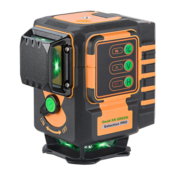
BEDIENELEMENTE 1. 1/4“-Gewinde 2. Libelle 3. Tastatur 4. Batteriefachdeckel 5. Anschluss für Dauerstromversorgung über das Ladegerät 6. Laserausgangsfenster 7 . AN-/AUS-Schalter / Entriegelungshebel (Transportsicherung) Empfängerbetrieb / Manuell- Manuellfunktion Empfangs-LED vertikale Linie V horizontale Linie H AN-/AUS-LED... - Seite 6 ZUBEHÖRE Höhenverstellbare Plattform · individuell höhenverstellbare Plattform im Bereich von 25 bis 85 mm; für höhen- korrekte Verlegung von Bodenfliesen und Riemchenfliesen rutschfeste Oberfläche Höhen- verstellung Wandhalterung · höhenverstellbar mit schwenkbarer Halteschiene Verbindungsschiene · frei hängende Befestigung am Stativ für beste Liniendarstellung am Boden; frei im Raum drehbar...
- Seite 7 20 mm-Adapter mit 5/8“ · für den Aufbau auf dem Boden · für den Stativanschluss 5/8“ · fixe Höhe: 20 mm von der Unter- kante zur Laserebene Höhenprüfpins · Überprüfung von Bodenunebenheiten mittels Höhenkontrollpins · Horizontal und vertikal Nivellieren mit 3 x 360° grünen Laserlinien ·...
-
Seite 8: Bedienung
BEDIENUNG Gerät aufstellen: · auf den 20 mm-Adapter aufklicken und auf dem Boden ausrichten · auf den 20 mm-Adapter aufklicken und auf einem Stativ befestigen · mit der im Lieferumfang enthaltenen höhenverstellbaren Plattform auf dem Boden ausrichten · mit der Verbindungsschiene an einem Stativ befestigen ·... -
Seite 9: Manuell -Funktion
SCHALTBARE LASERLINIEN MANUELL -FUNKTION Wenn sich das Gerät in OFF-Position befindet, Taste MANUELLfunktion einmal drücken, um die MANUELL -Funktion einzuschalten; die AN/AUS-LED leuchtet, die MANUELL -LED blinkt. Nun kann das Gerät auch schräg eingesetzt werden; der Kompensatoralarm ist aus. Alle Linien können nun wie im Standardmodus geschaltet werden. -
Seite 10: Sicherheitshinweise
SICHERHEITSHINWEISE UMSTÄNDE, DIE DAS MESSERGEBNIS VERFÄLSCHEN KÖNNEN Messungen durch Glas- oder Plastikscheiben; verschmutzte Laseraustrittsfenster; Sturz oder starker Stoß. Bitte Genauigkeit überprüfen. Große Temperaturveränderungen: Wenn das Gerät aus warmer Umgebung in eine kalte oder umgekehrt gebracht wird, vor Benutzung einige Minuten warten. UMGANG UND PFLEGE Messinstrumente generell sorgsam behandeln. -
Seite 11: Bestimmungsgemässe Verwendung
Das Gerät darf ohne weitere Sicherheitsmaßnahmen eingesetzt werden. Das Auge ist bei zufälligem, kurzzeitigem Hineinsehen in den Laserstrahl durch den Lidschlussreflex geschützt. Laserwarnschilder der Klasse 2 sind gut sichtbar am Gerät angebracht. www.geo-fennel.de G ERM AN Y Laser IEC 60825-1:2014 P ≤... - Seite 12 Dear customer, Thank you for your confidence in us having purchased a geo-FENNEL instrument. This manual will help you to operate the instrument appropriately. Please read the manual carefully - particularly the safety instructions. A proper use only guarantees a longtime and reliable operation.
-
Seite 13: Technical Data
FEATURES · 3 x 360° lines => form 6 laser crosses · Laser lines switchable separately · Plumbing function · Minimum laser plane distance to floor 8 mm · Minimum laser plane distance to wall 6 mm · Height adjustable platform in a range of 25 to 85 mm ·... -
Seite 14: Power Supply
POWER SUPPLY ALKALINE BATTERIES Open the battery compartment cover (4) and remove the alkaline battery box. Insert alkaline batteries (take care of correct polarity!) and insert the box into the battery case. Close the battery compartment cover. In case the ON/ OFF LED starts flashing the batteries must be exchanged or the rechargeable battery must be charged. -
Seite 15: Operating Elements
OPERATING ELEMENTS 1. 1/4“ thread 2. Vial 3. Keypad 4. Battery compartment cover 5. Connection for permanent power supply 6. Laser emitting window 7 . ON/OFF knob (transport lock) Receiving mode / MANUAL MANUAL function Receiving LED vertical line V horizontal line H ON/OFF LED... - Seite 16 ACCESSSORIES Height adjustable platform · individually height-adjustable platform in the range of 25 to 85 mm; for height- correct laying of floor tiles non-slip surface height adjustment knob Wallmount · height adjustable with swivel-mounted support rail Support rail · free-hanging tripod mounting for best line visibility at the floor...
- Seite 17 20 mm fix-height adapter with 5/8“ · for use on the floor direct · for connection to a tripod with 5/8“ · fix height: 20 mm from the bottom line to the laser plane Height checking pins · checking of floor flatness by use of height-check pins ·...
- Seite 18 OPERATION Setting up the laser: 1. click the laser onto the 20 mm fix-height adapter and align it on the floor 2. click the laser onto the 20 mm fix-height adapter and fix it onto a tripod 3. set the laser onto the heigt adjustable platform and align it on the floor 4.
-
Seite 19: Manual Function
SWITCHABLE LASER LINES MANUAL FUNCTION If the instrument is in OFF position press the button MANUAL function to enter into the MANUAL mode; the ON/OFF LED is illuminated, the MANUAL LED is blinking. Now the instrument can be used in slope mode, the compensator alarm is off. All lines can now be switched as in standard mode. Switch off the MANUAL function with the button MANUAL function USE WITH RECEIVER To prolong the working range or at unfavourable light conditions Geo6-XR GREEN SP can be used with... -
Seite 20: Safety Notes
SAFETY NOTES SPECIFIC REASONS FOR ERRONEOUS MEASURING RESULTS Measurements through glass or plastic windows; dirty laser emitting windows; after the instrument has been drop- ped or hit. Please check the accuracy. Large fluctuation of temperature: If the instrument will be used in cold areas after it has been stored in warm areas (or the other way round) please wait some minutes before carrying out measurements. -
Seite 21: Intended Use Of Instrument
It is allowed to use the unit without further safety precautions. The eye protection is normally secured by aversion responses and the blink reflex. The laser instrument is marked with class 2 warning labels. www.geo-fennel.de GERM ANY Laser IEC 60825-1:2014 P ≤... - Seite 22 Cher client, Nous tenons à vous remercier pour la confiance que vous avez témoignée, par l‘acquisition de votre nouvel instrument geo-FENNEL. Les instructions de service vous aideront à vous servir de votre instrument de manière adéquate. Nous vous recommandons de lire avec soin tout particulièrement les consignes de sécurité de ladite notice avant la mise en service de votre appareil.
- Seite 23 CARACTÉRISTIQUES · 3 lignes 360° => génèrent 6 croix laser · Lignes laser s'allument indépendement · Fonction d'aplomb · Distance minimum du sol 8 mm · Distance minimum du mur 6 mm · Plateforme ajustable en hauteur de 25 à 85mm ·...
-
Seite 24: Alimentation En Courant
ALIMENTATION EN COURANT PILES ALCALINES Ouvrez le clapet du compartiment piles (4) et retirez le bloc de piles de secours. Y placez les piles alcalines (prenez soin de la polarité) et remettez le bloc dans l‘instrument. Fermez le clapet. Si la diode MARCHE/ARRÊT clignote les piles doivent être changées our l‘accu doit être chargé. - Seite 25 DESCRIPTION 1. Filetage 1/4“ 2. Nivelle 3. Clavier 4. Couvercle du logement de piles 5. Douille pour alimentation en permanence 6. Fenêtre de sortie des faisceaux laser 7 . Interrupteur MARCHE/ARRÊT (blocage compensateur) Diode fonction Touche fonction réception MANUEL Touche fonction MANUEL Diode fonction Touche ligne verticale V réception...
-
Seite 26: Support Mural
ACCESSOIRES Plateforme ajustable en hauteur · plateforme individuellement ajustable en hauteur de 25 à 85 mm; pour une pose correcte des carreaux au sol superficie antiglisse bouton de réglage en hauteur Support mural · réglable en hauteur avec support rail pivotant Support rail ·... - Seite 27 Adaptateur 20 mm (également pour connexion trépied 5/8„) · pour la mise en place directement sur le sol · pour la connexion 5/8“ d‘un trépied · hauteur fixe: 20 mm du sol à la plaine du laser 3 plots de contrôle de hauteur ·...
- Seite 28 OPÉRATION Mise en place de l‘appareil: 1. cliquez le laser sur l‘adaptateur 20 mm et le placez sur le sol 2. cliquez le laser sur l‘adaptateur 20 mm et le placez sur un trépied 3. fixez le laser sur la plateforme ajustable en hauteur et le placez sur le sol 4.
- Seite 29 LIGNES POUVANT ÊTRE PROJETÉES FONCTION MANUEL Lorsque l’instrument se trouve en position OFF , pressez la touche fonction MANUEL une seule fois pour mettre en circuit la fonction MANUEL. La diode ON/OFF s’allume, la diode MANUEL clignote et les lignes laser sont en mesure de fonctionner. L ’instrument peut alors être utilisé en position inclinée et l’alarme du compensateur est hors circuit.
-
Seite 30: Consignes De Sécurité
CONSIGNES DE SÉCURITÉ CIRCONSTANCES POUVANT FAUSSER LES RÉSULTATS DE MESURES Mesures effectuées à travers des plaques de verre ou de matière plastique; mesures effectuées à travers la fenêtre de sortie du faisceau laser lorsqu‘elle est sale. Mesures après que le niveau soit tombé ou ait subi un choc très fort. Mesures effectuées pendant de grandes différences de température - p. -
Seite 31: Exclusion De La Responsabilité
être utilisé sans avoir recours à d’autres mesures de sécurité. Au cas où l’utilisateur a regardé un court instant le faisceau laser, les yeux sont tout de même protégés par le réflexe de fermeture des paupières. Les pictogrammes de danger de la classe 2 sont bien visibles sur le niveau. www.geo-fennel.de GERM ANY Laser IEC 60825-1:2014 P ≤... - Seite 32 GmbH geo-FENNEL GmbH Technische Änderungen vorbehalten. Technische Änderungen vorbehalten. Kupferstraße 6 All instruments subject to technical changes. All instruments subject to technical changes. Kupferstraße 6 D-34225 Baunatal Sous réserve de modifications techniques. Sous réserve de modifications techniques. D-34225 Baunatal Tel.