Werbung
Verfügbare Sprachen
Verfügbare Sprachen
Quicklinks
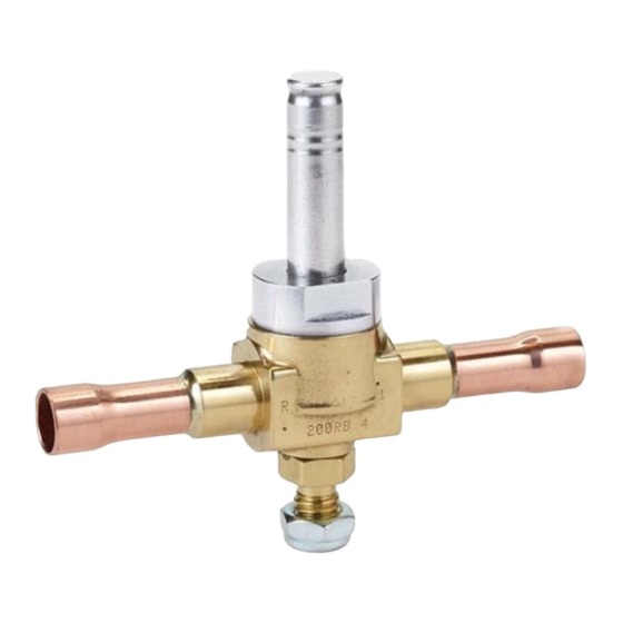
110RB/200RB/240RA/540RA
General information and technical data:
110RB/200RB/240RA Solenoid Valves are used for
shut-off purpose during operation on liquid, suction and
discharge line. Valve except 540RA are normally closed
types (NC), means when coil is de-energized valve is in
closed position. 540RA is normally open type (NO).
• Max. Operating Pressure PS: 31 bar;
• Max. Test Pressure PT: 34 bar; 540RA 20: 31 bar
• Operating Temperature Range TS: –40°C to 120°C
• Max. Ambient Temperature:
• Max. Transport Temperature: -40 to 70°C
• Max. body temperature:
• Valves with Tube Connection >32mm are CE
marked, except 540RA.
• Valves are in compliance with prEN 12284
• ASC Coil with IP 65 protection class (DIN 43650)
• Compatibility: CFC, HCFC, HFC, Mineral- and
Ester Lubricants
•
!
Safety instructions:
Read
installation
instructions
•
Failure to comply can result in device failure,
system damage or personal injury.
It is intended for use by persons having the
•
appropriate
knowledge
and
attempting to install the solenoid valve make
sure pressure in system is brought to and
remains at atmospheric pressure.
Do not release any refrigerant into the
•
atmosphere.
Do not use any other fluid media without prior
•
approval of Alco Controls. Use of fluid not
listed could result in:
Change of Hazard Category of the product and
consequently change of conformity assessment
requirement for product in accordance with
European
Pressure
Equipment
97/23/EC.
In a severely contaminated system, avoid
•
breathing acid vapours and avoid contact with
skin from contaminated refrigerant / lubricants.
Failure to do so could result in skin injury.
WARNING: Do not use a solenoid valve as a
•
safety shut-off valve or for service purpose.
The solenoid coil should be fused in accordance
•
with local codes. Electrically ground the valve
body.
WARNING: Do not energize Coil unless it is
•
attached to the valve.
110RB/200RB/240RA are not released for use
•
with
flammable
refrigerants
hydrocarbon refrigerants and ammonia.
Before any service disconnect power supply
•
from coil.
Mounting location:
• 110RB/200RB/240RA should be installed as close
as possible to the device to be shut-off/controlled
by the valve.
• Allow sufficient clearance above the valve for
removal of Coil.
• Valves may be mounted in horizontal or vertical
lines (Fig. 1). Up-side down position is not
allowed and can cause mal-function (Fig. 2).
SOL__65057__R05.doc
replaces / ersetzt R04
Operating Instructions
Solenoid Valve Series
Installation of Valve:
• Do not dent, bend, or use the enclosing tube as a
lever. A damaged enclosing tube may result in coil
burnout, inoperative valve or leakage.
• Direction of flow must match arrow on body.
• Before brazing clean tubing.
• Do not disassamble valve before brazing.
540RA 20: 28 bar
• Direct flame away from valve body (Fig. 3).
• Use an inert gas such as nitrogen to pass through
the valve to prevent copper oxide formation.
-40 to 50°C
• The use of appropriate brazing material is required
(soft solder is not allowed). During brazing process
120°C
the cooling of the valve body is necessary to avoid
any internal damage(i.e. wet cloths). Do not
exceed max. body temperature of 120°C.
• Never use oxygen or flammable gases.
• Internal parts must be protected from foreign
material and moisture. ALCO filter-drier use in
liquid line and ALCO filter use in suction line is
recommended.
• Before energizing the valve be sure that the source
voltage and frequency matches that on the coil
label.
Installation of Coil:
thoroughly.
• Place coil over the enclosing tube. Coil may be
rotated 360° for ease of wiring.
• Press coil housing down firmly, secure (1) and
skill.
Before
close (2) the coil retainer (Fig. 4).
Wiring With Cable Assembly (Fig. 5)
• Color code: 1 = brown, 2 = blue, 3 = yellow/green
• Standard Cable (230V, 50Hz, 6 Amp max.)
Type
ASC-N15 804 570
ASC-N30 804 571
ASC-N60 804 572
ASC-L15 804 573
ASC-L30 804 574
ASC-L60 804 575
Directive
• Chopper Cable (26.5 V DC, 0.3 Amp max.) for
use with ASC 24 V / 50 - 60 Hz (801 062) only.
DS2-N15
DS2-N30
DS2-N60
DS2-L60
Wiring With Plug ASC-NM6
(Order nr. 804 576)
• Cable must be connected to terminal 1 and 2 on the
plug terminal box +
wired DIN-plug (Fig. 5) to the coil and tighten
screw with 0,1Nm.
such
as
Testing:
• Before Testing let the parts cool down to a
temperature <40°C.
• Cycle valve several times. A distinct click should
be heard each time the solenoid is energized.
• NOTE: ALCO solenoid valves are equipped with
a continous-duty coil, which when energized for an
extended period of time becomes hot. This is
normal.
Leakage test:
• After completion of installation, a pressure test
must be carried out as follows:
- According to EN378 for systems which must
comply
directive 97/23/EC
- To maximum working pressure of system for
other applications.
Emerson Electric GmbH & Co. OHG
Heerstr.111 – D-71332 Waiblingen
GB
www.ecopeland.com/alcoliterature.cfm
Order Nr. Length
Temperature
1.5 m
-25 ... +80°C
3.0 m
-25 ... +80°C
6.0 m
-25 ... +80°C
1.5 m
-50 ... +80°C
3.0 m
-50 ... +80°C
6.0 m
-50 ... +80°C
804 620
1.5 m
-25 ... +80°C
804 621
3.0 m
-25 ... +80°C
804 622
6.0 m
-25 ... +80°C
804 625
6.0 m
-50 ... +80°C
(ground) . Connect pre-
with
European
pressure
equipment
PCN 860 592
Tel.: 07151 509-0 - Fax.: -200
Warning:
1. Failure to do so could result in loss of refrigerant
and personal injury.
2. The pressure test must be conducted by skilled
persons with due respect regarding the danger
related to pressure.
Service:
• Before any service shut down system and disconnect
from power source.
• Fully depressurize Valve. After reducing pressure to
atmospheric the valve may be opened and internal
parts removed and replaced. Clean parts before re-
installation. Install parts in reverse sequence
removed (Fig. 6-8).
Recommended Torque (Nm)
Type
Bolts
110 RB
-
200 RB
-
240 RA 8-16
9
240 RA 20
12
Maximum and min. operating pressure Differentials
Pressure Differential (bar)
Type
Max.
Operating
Differential
AC 50 Hz
110 RB
25
200 RB
25
240 RA
25
Partslist Fig. 6-8
Part-
Description
No.
1
Coil retainer
2
DIN plug
3
Coil
4
Enclosing Tube
5
Spring
6
Plunger
7
Gasket
8
Valve body
9
Screw+washer
10
Manual stem
11
Screw (4 pcs.)
12
Spring
13
Gasket
14
Diaphragm
15
Piston cpl.
16
Plug
Technical Data Coils
ASC Coil
Voltage
(V)
24V/50-60Hz
120V/50-60Hz
AC
230V/50-60Hz
12 V
24 V
DC
120 V
230 V
1 / 8
as
Encl. Tube
Manual Stem
10
-
10
34
10
34
10
34
Max.
Min.
Operating
operating
Differential
differential
AC 60Hz
50/60 Hz
25
0
21
0,05
25
0,05
110RB 200RB 240RA 540RA
X
X
X
X
X
X
X
X
X
X
X
X
X
X
X
X
X
X
X
X
X
X
X
X
X
X
X
X
X
X
X
X
X
X
X
X
X
X
X
X
X
X
X
X
X
X
X
Power
Inrush
Holding
Input
Current
Current
(W)
(I)
(I)
2
0,77
10 W
0,4
0,15
0,2
0,08
0,93
15 Watt
0,46
0,09
0,05
15.01.2008
Werbung

Verwandte Anleitungen für Emerson 110RB Serie


Inhaltszusammenfassung für Emerson 110RB Serie
- Seite 1 Operating Instructions Emerson Electric GmbH & Co. OHG Solenoid Valve Series Heerstr.111 – D-71332 Waiblingen Tel.: 07151 509-0 - Fax.: -200 110RB/200RB/240RA/540RA www.ecopeland.com/alcoliterature.cfm General information and technical data: Installation of Valve: Warning: • Do not dent, bend, or use the enclosing tube as a 110RB/200RB/240RA Solenoid Valves are used for 1.
-
Seite 2: Einbau
Betriebsanleitung Emerson Electric GmbH & Co. OHG Magnetventile Baureihe Heerstr.111 – D-71332 Waiblingen Tel.: 07151 509-0 - Fax.: -200 110RB/200RB/240RA/540RA www.ecopeland.com/alcoliterature.cfm • Fließrichtung muß mit dem Pfeil auf dem Beschreibung und technische Daten: Service: Ventilkörper übereinstimmen. 110RB/200RB/240RA Magnetventile werden zur •... - Seite 3 Instrucciones de funcionamiento Emerson Electric GmbH & Co. OHG Electroválvulas de las series Heerstr.111 – D-71332 Waiblingen Tel.: 07151 509-0 - Fax.: -200 110RB/200RB/240RA/540RA www.ecopeland.com/alcoliterature.cfm Directiva 97/23/CE relativa a los equipos a presión Información general características Instalación de la válvula: –...
- Seite 4 Istruzioni di Installazione Emerson Electric GmbH & Co. OHG Valvole Solenoidi Serie Heerstr.111 – D-71332 Waiblingen Tel.: 07151 509-0 - Fax.: -200 110RB/200RB/240RA/540RA www.ecopeland.com/alcoliterature.cfm Informazioni Generali e Dati Tecnici: Installazione della valvola: Attenzione: • Non ammaccare, piegare o utilizzare come leva il...
- Seite 5 Instructies voor het gebruik Emerson Electric GmbH & Co. OHG Magneetventielen Heerstr.111 – D-71332 Waiblingen Tel.: 07151 509-0 - Fax.: -200 110RB/200RB/240RA/540RA www.ecopeland.com/alcoliterature.cfm • Zorg voor voldoende ruimte boven Algemene en technische gegevens: Lektest: magneetventiel zodat de spoel verwijderd kan...
- Seite 6 Základní údaje Emerson Electric GmbH & Co. OHG Elektromagnetické ventily Heerstr.111 – D-71332 Waiblingen Tel.: 07151 509-0 - Fax.: -200 110 RB, 200 RB,240 RA, 540RA www.ecopeland.com/alcoliterature.cfm • Ventil nemusí být rozebírán před pájením Elektromagnetické ventily řady 110 RB, 200 RB a zásahem do systému je nutno snížit tlak na...
- Seite 7 Инструкция по эксплуатации Emerson Electric GmbH & Co. OHG Соленоидные вентили серий Heerstr.111 – D-71332 Waiblingen Tel.: 07151 509-0 - Fax.: -200 110 RB, 200 RB,240 RA, 540RA www.ecopeland.com/alcoliterature.cfm Монтаж вентиля: Испытание на герметичность: Основные параметры и технические данные: • Не сминать, не сгибать и не использовать...
- Seite 8 Emerson Electric GmbH & Co. OHG 110 RB, 200 RB,240 RA, 540RA Heerstr.111 – D-71332 Waiblingen Tel.: 07151 509-0 - Fax.: -200 www.ecopeland.com/alcoliterature.cfm Fig. 1 Fig. 2 110RB 200RB Fig. 4 Fig. 3 240RA / 540RA Fig. 5 Fig. 6 (110 RB) Fig.