Werbung
Verfügbare Sprachen
Verfügbare Sprachen
Quicklinks
G e n e r a l i n f o r ma t i o n :
Electronic oil level management system OM5 TraxOil is developed and optimized
for transcritical CO
systems, using a Hall-Sensor to measure the oil level. A
2
magnetic float changes its position according to the oil level. The alarm contact
may be used to shut down the compressor. For application in refrigeration systems
and heat pumps according to EN 378.
S a f e t y i n s t r u c t i o n s :
• Read operating instructions thoroughly. Failure to comply can result in
device failure, system damage or personal injury.
• According to EN 13313 it is intended for use by persons having the
appropriate knowledge and skill.
• In a severely contaminated system, avoid breathing acid vapors and avoid
contact with skin from contaminated refrigerant / lubricants. Failure to do
so could result in injury.
• Before opening any system make sure pressure in system is brought to and
remains at atmospheric pressure.
• Do not exceed the specified maximum ratings for pressure, temperature,
voltage and current.
• Before installation or service disconnect all voltages from system and device.
• Warning: Float contains lead and has to be recycled after operation!
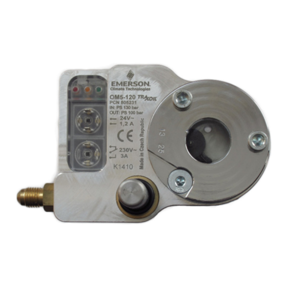
S y s t e m c o m p o n e n t s ( F i g . 1 , 2 , 3 , 5 )
1
Screws (2x)
2
Countersunk screw (below coil)
3
Sight glass
4
Sight glass O-ring – 33x2,6
5
Adapter O-ring – 25x2,6
6
Adapter (flange or screw)
7
Compressor O-ring (optional)
Teflon gasket (-CCD/-CCE)
8
Coil connector OM3-Pxx or
OM-230V-x with screw M3x21
A : I n s t a l l a t i o n w i t h F l a n g e A d a p t e r s : ( s e e F i g . 1 , 2 , 3 , 5 )
Adapter types OM0-CUA, -CCC, -CCD, -CCE, -CUD
1. Remove and discard the plastic holding rings from the back side of OM5 which
secure screws and sight glass during transportation.
2. Locate the grove stamped into the adapter ring in line with the main body
marking (Fig. 5). Mount the base unit (12) including O-ring (5) to the adapter (6),
torque 12 Nm.
3. Remove the sight-glass from the compressor.
4. Mount O-ring (7) to the adapter (6)
5. OM0-CCD/-CCE: mount the teflon ring into the compressor
6. Mount OM5 to the compressor's original sight glass connection and use original
sight glass screws - threads differ depending on compressor model.
For proper function the unit must be installed horizontally (see Fig. 1 & 2).
7. Mounting torque: -CCD 90 Nm (wrench size 50 mm); -CCE 65 Nm (wrench size
42 mm). All others see compressor manufacturer's installation instructions.
8. For mounting of the coil please refer to coil operating instruction. Then connect
OM3-Pxx or OM-230V-x (8) and OM3-Nxx (9) cable assemblies to OM5 and
coil. Recommended torque for the plug screws is 0.15 Nm (hand-tight).
9. Install the oil supply line to 7/16-20 UNF thread (13). Oil connector with screen
and O-ring can be removed for cleaning purpose or replacement (see Fig. 3).
Note: Check Rotalock adapters for tightness after 1-2 days of operation.
B : I n s t a l l a t i o n w i t h S c r e w A d a p t e r s : ( s e e F i g . 1 , 2 , 3 , 5 )
Adapter types OM0-CBB, -CCA, -CCB
• For proper function the unit must be installed horizontally (see Fig. 1 & 2)
1. Remove and discard the plastic holding rings from the back side of OM5 which
secure screws and sight glass during transportation.
2. Screw adapter onto compressor sight glass thread (use mounting torque specified
by the compressor manufacturer) as follows:
Type -CBB: mount O-ring (7) to the adapter (6).
Type -CCA: apply Teflon sealant to adapter thread.
Type -CCB: locate O-ring (7) inside compressor sight glass thread - do not reuse
old sight glass O-ring.
3. Locate the grove stamped into the adapter ring in line with the main body
marking (Fig. 5). Mount the base unit including O-ring (5) to the adapter (6),
torque 12 Nm.
4. For mounting of the coil please refer to coil operating instruction. Then connect
OM3-Pxx or OM-230V-x (8) and OM3-Nxx (9) cable assemblies to OM5 and
coil. Recommended torque for the plug screws is 0.15 Nm (hand-tight).
5. Install the oil supply line to 7/16-20 UNF thread (13). The oil connector with
strainer and O-ring can be removed for cleaning purpose or replacement (see
Fig. 3).
Emerson Climate Technologies GmbH
Holzhauser Str. 180 I 13509 Berlin I Germany
Operating instruction
Oil Management System Series OM5 TraxOil
9
Relay connector OM3-Nxx with
screw M3x35
10 Solenoid coil ASC3-W, 24V or
230V, 18W, incl. 2x O-ring & Cap
11 Coil Cap ASC3
12 Base unit
13 7/16"-UNF oil connector incl. O-ring
14 Oil connector O-ring – 7,6x1,8
www.emersonclimate.eu
P r e s s u r e T e s t :
After completion of installation, a pressure test must be carried out as follows:
- according to EN 378 for systems which must comply with European pressure
equipment directive 97/23/EC.
- to maximum working pressure of system for other applications.
W a r n i n g :
• Failure to do so could result in loss of refrigerant and personal injury.
• The pressure test must be conducted by skilled persons with due respect
regarding the danger related to pressure.
T i g h t n e s s T e s t :
Conduct a tightness test according to EN 378-2 with appropriate equipment and
method to identify leakages of external joints. The allowable leakage rate must be
according system manufacturer's specification.
W i r i n g :
Note: plugs do not require additional gaskets. Do not switch the compressor
directly. Use compressor's power relay instead. See Fig. 4 for connection of
OM5 to the safety loop (SL) of a rack controller.
• Connect the OM3-Nxx (9) cable to the relay connection according Fig. 1,2,4:
BU
= blue
(open in Alarm)
BN
= brown (closed in Alarm)
For 24 V Supply
• The OM3-Pxx cable assembly requires ASC3-W coil with 24 VAC.
• Connect OM3-Pxx (8) wires to the power supply (i.e. ECT-623) acc. Fig. 1
For 230 V Supply
• The OM-230V-x transformer cable with 230V-W module requires ASC3 coil
with 230 VAC.
• Connect OM-230V-x (8) wires to power supply acc. Fig. 2.
BU
= blue - Neutral N
GN/YE
= green/yellow - Ground GND
O p e r a t i o n : ( F i g . 4 )
OM5 is fully level controlled. The sight glass of each device is divided into three
operational zones. When the level reaches the yellow zone (YE) the OM5 starts
filling after a time delay of 10 sec. Further level drop to the red zone (RE) will
switch the alarm relay after a time delay of 120 sec.
The current status is indicated with the 3 LEDs according to the following table:
LED
Status / Function
Green
Oil Level in zone 1 (60 - 40%)
Oil Level in zone 1 (60 - 40%) & Injection
Green
Yellow
Yellow
Oil Level in zone 2 (40 - 25%) & Injection
Red
Yellow
Oil Level in zone 3 (25 - 0%) & Injection
To provide the correct oil level at any time we recommend to keep the OM5
always powered on (also during compressor stand-by and shutdown mode).
First Installation: After connecting OM5 to power supply and oil level below
60%, OM5 starts injecting after 10sec delay, to bring oil immediately to a safe
level.
T e c h n i c a l D a t a :
Max. working pressure PS:
Test pressure PT:
Solenoid MOPD:
Supply voltage
24V / 230V -0%
24V / 230V -10%
Supply voltage:
24 VAC, 50/60 Hz, 230 VAC, 50/60 Hz, (+10/-10%)
Solenoid coil:
Current:
Alarm contact rating:
Medium compatibility:
Time delay filling:
Time delay alarm:
Medium temperature:
Storage, transport and ambient temperature (housing):
Protection class (IEC529/EN60529):
Alarm switch:
Oil supply fitting:
Flow Capacity:
Markings:
A c c e s s o i r e s :
•
Transformer 230VAC/24VAC, 60VA (ECT-623)
Date: 25.11.2014
BK
=
black
(common)
BN
= brown - Phase L1
High pressure side (oil connection): 130 bar
Low pressure side (compressor): 100 bar
Lower voltage supplies lead
MOPD
to a reduced max. pressure
100 bar
differential.
80 bar
ASC3-W24VAC, 50/60Hz, 18W
ASC3-W230VAC, 50/60Hz, 18W
HFC, HCFC, CO
7/16"-20 UNF (male)
see Technical Bulletin
acc. EMC & Low Voltage Directive
OM5_OI_ML_R02_865911.docx
143 bar
0.7 A
3A/230 VAC
2
10 sec
120 sec
-20...80 °C
-20...50 °C
IP65
SPDT
,
Werbung

Verwandte Anleitungen für Emerson OM5 TraxOil


Inhaltszusammenfassung für Emerson OM5 TraxOil
- Seite 1 G e n e r a l i n f o r ma t i o n : P r e s s u r e T e s t : Electronic oil level management system OM5 TraxOil is developed and optimized After completion of installation, a pressure test must be carried out as follows: for transcritical CO systems, using a Hall-Sensor to measure the oil level.
- Seite 2 B e s c h r e i b u n g : Type -CCA: Teflondichtmaterial auf das Adaptergewinde aufbringen. Das elektronische Ölmanagementsystem OM5 TraxOil wurde für transkritische Type -CCB: O-Ring (7) ins Schauglasgewinde des Verdichters einlegen. Alten Systeme entwickelt und optimiert. Der Ölstand wird mittels eines Hall-Sensors O-Ring des Schauglases entsorgen - nicht wiederverwenden.
- Seite 3 Betriebsanleitung OM5 TraxOil Ölmanagement T e c h n i s c h e D a t e n : Z u b e h ö r : Max. Betriebsdruck PS: Hochdruckseite (Ölanschluss): 130 bar • Transformator 230VAC/24VAC, 60VA (ECT-623) Niederdruckseite (Verdichter): 100 bar Prüfdruck PT:...
- Seite 4 Première mise en route: Lors de la mise sous tension alors que le niveau est inférieur à 60 %, l’OM5 va commencer à injecter après 10 sec.de temporisation afin de compléter immédiatement le niveau. Emerson Climate Technologies GmbH www.emersonclimate.eu Holzhauser Str. 180 I 13509 Berlin I Germany Date: 25.11.2014...
- Seite 5 Classe de protection: (IEC529/EN60529): IP65 Contact d'alarme: SPDT Orifice d’entrée d’huile: 7/16”-20 UNF (male) Débit: voir Technical Bulletin Marquage: pour EMC & directive brasse pression Emerson Climate Technologies GmbH www.emersonclimate.eu Holzhauser Str. 180 I 13509 Berlin I Germany Date: 25.11.2014 OM5_OI_ML_R02_865911.docx...
- Seite 6 I n f o r ma c i ó n g e n e r a l : fabricante): El sistema de control de nivel de aceite OM5 TraxOil está optimizado para Typo -CBB: Monte la junta tórica (7) en el adaptador (6).
- Seite 7 Tipo de contacto alarma: SPDT Conexión alimentación de aceite: 7/16”-20 UNF (male) Capacidad de flujo: ver Technical Bulletin Marcado: directivas de Compatibilidad electromagnética y bajo voltaje Emerson Climate Technologies GmbH www.emersonclimate.eu Holzhauser Str. 180 I 13509 Berlin I Germany Date: 25.11.2014 OM5_OI_ML_R02_865911.docx...
- Seite 8 2. Avvitare l’adattatore sulla filettatura della spia olio del compressore (usare la coppia di serraggio specificata dal costruttore del compressore) come segue: Emerson Climate Technologies GmbH www.emersonclimate.eu Holzhauser Str. 180 I 13509 Berlin I Germany Date: 25.11.2014...
- Seite 9 Classe di protezione: (IEC529/EN60529): IP65 Contatto allarme: SPDT Connessione linea olio: 7/16”-20 UNF (male) capacità di flusso: vedere Technical Bulletin Marchio: secondo EMC e Basso Voltaggio Emerson Climate Technologies GmbH www.emersonclimate.eu Holzhauser Str. 180 I 13509 Berlin I Germany Date: 25.11.2014 OM5_OI_ML_R02_865911.docx...
- Seite 10 B : У С Т А Н О В К А С Р Е З Ь Б О В Ы М А Д А П Т Е Р О М Электронный регулятор уровня масла OM5 TraxOil, разработанный и Модель OM0-CBB, -CCA, -CCB (см. рис. 1,2,3,5) оптимизированный...
- Seite 11 Д о п о л н и т е л ь н о е о б о р у д о в а н и е : • Трансформатор 230B/24B, 60BA (ECT-623) Emerson Climate Technologies GmbH www.emersonclimate.eu Holzhauser Str. 180 I 13509 Berlin I Germany Date: 25.11.2014...
- Seite 12 Oil Management System Series OM5 TraxOil Fig. 1 24 VAC Power supply Fig. 2: 230 VAC power supply Fig. 3 Fig. 4 Fig. 5: Components Emerson Climate Technologies GmbH www.emersonclimate.eu Holzhauser Str. 180 I 13509 Berlin I Germany Date: 25.11.2014...