Pilz PZE X4.1P Benutzerhandbuch
Vorschau ausblenden
Andere Handbücher für PZE X4.1P:
- Betriebsanleitung (17 Seiten) ,
- Bedienungsanleitung (22 Seiten)
Inhaltsverzeichnis
Werbung
Quicklinks
21102-01
PZE X4.1P
Sicherheitsbestimmungen
• Das Gerät darf nur von Personen instal-
liert und in Betrieb genommen werden,
die mit dieser Betriebsanleitung und den
geltenden Vorschriften über Arbeitssicher-
heit und Unfallverhütung vertraut sind.
Beachten Sie die VDE- sowie die örtlichen
Vorschriften, insbesondere hinsichtlich
der Schutzmaßnahmen.
• Halten Sie beim Transport, bei der Lage-
rung und im Betrieb die Bedingungen
nach EN 60068-2-6 ein (siehe technische
Daten).
• Durch Öffnen des Gehäuses oder eigen-
mächtige Umbauten erlischt die Gewähr-
leistung.
• Montieren Sie das Gerät in einen Schalt-
schrank; Staub und Feuchtigkeit können
sonst zu Beeinträchtigungen der Funktio-
nen führen.
• Sorgen Sie an allen Ausgangskontakten
bei kapazitiven und induktiven Lasten für
eine ausreichende Schutzbeschaltung.
• Die Sicherheitsfunktion muss mindestens
einmal im Monat ausgelöst werden.
Bestimmungsgemäße Verwendung
Der Kontaktblock PZE X4.1P erfüllt die For-
derungen der EN 60204-1 und IEC 60204-1.
Das Gerät dient als Erweiterungsgerät zur
Kontaktverstärkung und Kontakt-
vervielfachung für ein Grundgerät. Grund-
geräte sind alle Sicherheitsschaltgeräte mit
Rückführkreis.
Die zu realisierende Kategorie nach EN 954-
1 ist abhängig von der Kategorie des Grund-
geräts. Sie kann vom Kontakterweiterungs-
block nicht überschritten werden.
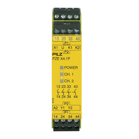
Gerätebeschreibung
Der Kontaktblock ist in einem S-99-Gehäuse
untergebracht. Die Versorgungsspannung
beträgt 24 ... 240 V AC/DC.
Merkmale:
• Relaisausgänge: 4 Sicherheitskontakte
(S), zwangsgeführt
• Anschluss für Rückführkreis
• Statusanzeige für Ausgangsrelais und
Versorgungsspannung
• wahlweise Schraub- oder
Kafigzugfederklemmen
Die Sicherheitseinrichtung bleibt auch nach
Ausfall eines Bauteils wirksam.
Funktionsbeschreibung
Der Kontaktblock PZE X4.1P dient der Er-
weiterung eines Sicherheitsstromkreises.
Der Kontaktblock wird von einem Grund-
gerät angesteuert.
Nach Anlegen der Versorgungsspannung
leuchtet die LED "POWER".
Sobald die Eingangskreise K1-U-K2 ge-
schlossen sind, gehen die beiden Aus-
gangsrelais in Arbeitsstellung. Die
Sicherheitskontakte 13-14, 23-24, 33-34 und
43-44 schließen, der Rückführkreis Y1-Y2
Safety regulations
• The unit may only be installed and
commissioned by personnel who are
familiar with both these instructions and
the current regulations for health and
safety at work and accident prevention.
Ensure VDE and local regulations are
met, especially those relating to safety.
• Transport, storage and operating
conditions should all conform to
EN 60068-2-6 (see "Technical details").
• The guarantee is rendered invalid if the
housing is opened or unauthorised
modifications are carried out.
• The unit should be panel mounted,
otherwise dust and moisture could
adversely affect its function.
• Sufficient fuse protection must be
provided on all output contacts with
capacitive and inductive loads.
• The safety function must be triggered at
least once a month.
Intended use
The contact block PZE X4.1P conforms to
the requirements of EN 60204-1 and
IEC 60204-1. The unit is an expander
module for increasing the number of
contacts available for a base unit. Base
units are all safety relays with feedback
loop.
The category to be implemented in
accordance with EN 954-1 depends on the
category of the base module. It cannot be
exceeded by the expander module.
Unit description
The contact block is enclosed in an S-99
housing. Supply voltage is 24 ... 240 V
AC/DC.
Features:
• Relay outputs: 4 safety contacts (N/O),
positive guided
• Connection for feedback loop
• Status indicator for output relay and
supply voltage
• Screw terminals or cage clamp terminals
The safety function remains effective even
after a component failure.
Function description
The contact block PZE X4.1P is used to
expand a safety circuit. The contact block is
driven from a base unit.
When operating voltage is supplied the
"POWER" LED is lit.
As soon as input circuits K1-U-K2 are
closed, both output relays switch to their
operating position. Safety contacts 13-14,
23-24, 33-34 and 43-44 close, feedback
loop Y1-Y2 is open. The LEDs "CH. 1" and
"CH. 2" are lit.
- 1 -
Consignes de sécurité
• L'installation et la mise en service de l'appa-
reil doivent être effectuées par une personne
qui s'est familiarisée avec le présent manuel
d'utilisation et avec les prescriptions relatives
à la sécurité du travail et à la prévention
d'accidents. Tenez compte des normes loca-
les ou VDE applicables, notamment en ce
qui concerne les mesures de protection.
• Pour le transport, le stockage et l'utilisation,
respectez les exigences de la norme
EN 60068-2-6 (voir caractéristiques techni-
ques).
• L'ouverture du boîtier ou toutes modifica-
tions faites par l'utilisateur rendent la ga-
rantie caduque.
• L'humidité et la poussière pouvant entraî-
ner des dysfonctionnements, l'appareil doit
être monté dans une armoire.
• Veillez à ce que tous les contacts de sortie
disposent d'un circuit de protection suffi-
sant en cas de charges capacitives et in-
ductives.
• La fonction de sécurité doit être déclen-
chée au moins une fois par mois.
Utilisation conforme aux prescriptions
Le bloc de contacts PZE X4.1P satisfait aux
exigences de l'EN 60204-1 et de
l'IEC 60204-1. L'appareil sert de module
d'extension pour l'augmentation et la
multiplication du nombre de contacts d'un
appareil de base. Les appareils de base
sont tous des blocs logiques de sécurité
équipés d'une boucle de retour.
La catégorie à réaliser selon l'EN 954-1
dépend de la catégorie de l'appareil de
base. Elle ne peut pas être dépassée par le
bloc d'extension de contacts.
Description de l'appareil
Le bloc de contacts est logé dans un
boîtier S-99. Sa tension d'alimentation est
de 24 ... 240 V AC/DC.
Caractéristiques :
• Sorties à relais : 4 contacts de sécurité
(F) à contacts liés
• Raccord pour la boucle de retour
• Affichage de l'état du relais de sortie et de
la tension d'alimentation
• au choix borniers à vis ou borniers à ressort
Le dispositif de sécurité reste actif, même
en cas de défaillance d'un composant.
Description du fonctionnement
Le bloc de contacts PZE X4.1P sert à l'exten-
sion d'un circuit de sécurité. Le bloc de con-
tacts est commandé par un appareil de base.
Après l'application de la tension d'alimenta-
tion, la LED "POWER" s'allume.
Dès que les circuits d'entrée K1-U-K2 sont
fermés, les deux relais de sortie passent en
position de travail. Les contacts de sécurité
13-14, 23-24, 33-34 et 43-44 se ferment, la
boucle de retour Y1-Y2 est ouverte. Les
LED "CH. 1" et "CH. 2" s'allument.
Werbung
Inhaltsverzeichnis

Verwandte Anleitungen für Pilz PZE X4.1P


Inhaltszusammenfassung für Pilz PZE X4.1P
- Seite 1 Description du fonctionnement Der Kontaktblock PZE X4.1P dient der Er- The contact block PZE X4.1P is used to Le bloc de contacts PZE X4.1P sert à l’exten- weiterung eines Sicherheitsstromkreises. expand a safety circuit. The contact block is sion d’un circuit de sécurité. Le bloc de con- Der Kontaktblock wird von einem Grund- driven from a base unit.
-
Seite 2: Montage
ist offen. Die LEDs “CH. 1” und “CH. 2” If one or both of the input circuits are Si l’un des deux circuits ou les deux circuits leuchten. opened the relays de-energise, safety d’entrée est/sont ouvert(s), les relais retom- Wird einer oder beide Eingangskreise geöff- contacts 13-14, 23-24, 33-34 and 43-44 bent, les contacts de sécurité... - Seite 3 Anschluss mit externer Versorgungs- Connection with external supply voltage • Respecter impérativement les données spannung • Connect the supply voltage to terminals indiquées dans le chapitre "Caractéristi- • Versorgungsspannung an Klemmen A1 (+) A1 (+) and A2 (-), connect the operating ques techniques".
- Seite 4 Ablauf Sequence Procédure Das Gerät ist eingeschaltet, wenn The unit is switched on when: L’appareil est enclenché lorsque • die Versorgungsspannung anliegt und die • Supply voltage is applied and the “PO- • la tension d'alimentation est appliquée et LED "POWER" leuchtet WER”...
-
Seite 5: Technische Daten
Technische Daten Technical details Caractéristiques techniques Versorgungsspannung U Supply voltage U Tension d’alimentation U 24 ... 240 V AC/DC Spannungstoleranz Voltage tolerance Plage de la tension d’alimentation - 15/+10% Leistungsaufnahme bei U Power consumption at U Consommation pour U 2 W/4 VA Restwelligkeit DC Residual ripple DC Ondulation résiduelle DC... -
Seite 6: Abmessungen In Mm /Dimensions In Mm /Dimensions En Mm
0224 2360180, Fax: 0224 2360184, E-Mail: pilz.tr@pilz.de Pilz Automation Safety L.P., 734 354-0272, Fax: 734 354-3355, E-Mail: info@pilzusa.com www.pilz.com ✆ Pilz GmbH & Co. KG, Sichere Automation, Felix-Wankel-Straße 2, 73760 Ostfildern, Deutschland, +49 711 3409-0, Fax: +49 711 3409-133, E-Mail: pilz.gmbh@pilz.de - 6 -... - Seite 7 Campo de aplicación adecuado Uso previsto Gebruik volgens de voorschriften El bloque de contactos PZE X4.1P satisface Il modulo contatti PZE X4.1P è conforme Het contactblok PZE X4.1P voldoet aan de los requerimientos según EN 60204-1 y alle norme EN 60204-1 e IEC 60204-1.
-
Seite 8: Montaje
En cuanto se cierran los circuitos de entra- Non appena i circuiti di ingresso K1-U-K2 Zodra het ingangscircuit K1-U-K2 is geslo- da K1-U-K2, ambos relés de salida pasan a sono chiusi, entrambi i relè di uscita passa- ten, gaan de beide uitgangsrelais in werk- la posición de trabajo. - Seite 9 contactos a través de los cuales se commutate in precedenza alte potenze. tacten schakelen die tevoren grote han conducido anteriormente grandes • Per i conduttori utilizzare materiale in filo stroomsterkten verwerkt hebben. corrientes. di rame con una resistenza termica intor- •...
- Seite 10 Procedimiento Procedura Procedure El dispositivo está conectado cuando Il dispositivo è attivato quando: Het relais is ingeschakeld als • se conecta la tensión de alimentación y el • è presente la tensione di alimentazione e • de voedingsspanning ingeschakeld is en LED "POWER"...
- Seite 11 Datos técnicos Dati tecnici Technische gegevens Tensión de alimentación U Tensione di alimentazione U Voedingsspanning U 24 ... 240 V AC/DC Tolerancia de tensión Tolleranza di tensione Spanningstolerantie - 15/+10% Consumo de energía con U Potenza assorbita per U Opgenomen vermogen bij U 2 W/4 VA Ondulación residual CC Ondulazione residua DC...
- Seite 12 0224 2360180, Fax: 0224 2360184, E-Mail: pilz.tr@pilz.de Pilz Automation Safety L.P., 734 354-0272, Fax: 734 354-3355, E-Mail: info@pilzusa.com www.pilz.com ✆ Pilz GmbH & Co. KG, Sichere Automation, Felix-Wankel-Straße 2, 73760 Ostfildern, Deutschland, +49 711 3409-0, Fax: +49 711 3409-133, E-Mail: pilz.gmbh@pilz.de - 12 -...