Werbung
Quicklinks
+050004182 - rel. 1.2 - 25.07.13
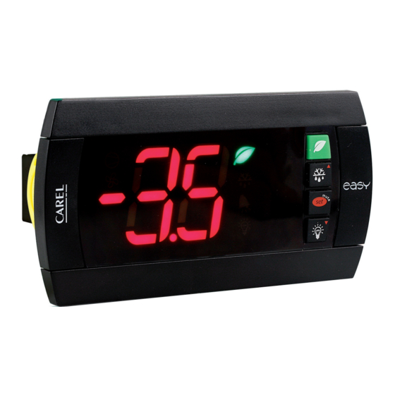
PJ easy XL
- ENERGY SALING z mikro wyłącznikiem drzwi / ENERGY SAVING with door switch
Wymiary w mm / Dimensions (mm)
156
134
4
127x69
Montaż na panelu / Panel mounting
Z przodu (2 śruby ø 4 mm) / Front (with 2 screws ø 4 mm)
Z tyłu (z 2 tylnymi uchwytami) / Rear (with 2 quick-fi t side brackets)
Podłączenia elektryczne / Electrical connections
-10T50
NTC
PROBES
1 2 3 4 5
6 7
8
L
N
230V~
L
przet. szeregowy / serial conv.
IROPZ485S0
klucz prog. / prog. key
IROPZKEY* or PSOPZKEY*
Tabela alarmów
Kod alarmu
brzęczyk i przekaźnik
LED
Opis alarmu
alarmowy
E0
aktywne
ON
błąd czujnika 1= regulacja
E1
nieaktywne
ON
błąd czujnika 2= odszranianie [d0 = 1/2/3]
E3
aktywne
ON
Alarm wycieku chłodziwa
dr
aktywne
ON
alarm z powodu otwartych
drzwi
LO
aktywne
ON
alarm niskiej temperatury
HI
aktywne
ON
alarm wysokiej temperatury
EE
nieaktywne
ON
błąd parametrów urządzenia
EF
nieaktywne
ON
błąd parametrów
funkcjonowania
dF
nieaktywne
OFF odszranianie w toku
Table of alarms
Alarm code
buzzer and alarm relay
LED
Description
E0
active
ON
probe 1 error= control
E1
inactive
ON
probe 2 error= defrost
E3
active
ON
refrigerant system failure alarm dE
dr
active
ON
open door alarm
LO
active
ON
low temperature alarm
HI
active
ON
high temperature alarm
EE
inactive
ON
unit parameter error
EF
inactive
ON
operating parameter error
dF
inactive
OFF defrost running
IMPORTANT WARNINGS
The CAREL product is a state-of-the-art product, whose operation is specifi ed in the technical
documentation supplied with the product or can be downloaded, even prior to purchase,
from the website www.carel.com. - The client (builder, developer or installer of the fi nal equip-
ment) assumes every responsibility and risk relating to the phase of confi guration the product
in order to reach the expected results in relation to the specifi c fi nal installation and/or equi-
pment. The lack of such phase of study, which is requested/indicated in the user manual, can
cause the fi nal product to malfunction of which CAREL can not be held responsible. The fi nal
client must use the product only in the manner described in the documentation related to
the product itself. The liability of CAREL in relation to its own product is regulated by CAREL's
general contract conditions edited on the website www.carel.com and/or by specifi c agree-
ments with clients.
Opis
PJ easy XL stanowi typoszereg mikroprocesorowych regulatorów elektronicznych z ekra-
nem LED zrealizowanych do zarządzania oszczędnością energii urządzeń chłodniczych
NO POWER
& SIGNAL
CABLES
TOGETHER
za pomocą kontroli mikro wyłącznika drzwi. Stan drzwi decyduje o zmianie set-point i
READ CAREFULLY IN THE TEXT!
włączeniu lub wyłączeniu światła.
Charakterystyka techniczna
zasilanie
230 Vac +10 /-15% 50/60 Hz; 115 Vac +10 /-15% 50/60 Hz
12 Vac +10/-15% 50/60 Hz klasy 2; 12 Vdc +10/-20% klasy 2
moc znamio-
3,5 VA
nowa
wejścia
czujnik NTC 2 wejścia. 1 wejście cyfrowe
przekaźniki na
2 Hp EN60730-1: 10(10) A 250 Vac
wyjściach
przekaźnik
przekaźnik
rodzaj czujnika
NTC Std CAREL 10 KΩ przy 25 °C
podłączenia
Zdejmowane konektory śrubowe do bloczków lub zaciskowe (przek. kabla
do 2,5 mm
montaż
na terminalu: za pomocą śrub od przodu lub za pomocą uchwytu z tyłu
wizualizacja
ekran LED 2 cyfrowy ze znakiem (-99...99) i przecinkiem dziesiętnym; sześć
LED stanu
warunki funkcjonowania
warunki magazynowania
zakres odczytu
stopień ochrony z przodu
pojemnik
49
klasyfi kacja według zabezpieczenia
59
przed wstrząsem elektrycznym
zanieczyszczenie środowiska
Wskaźnik PTI zastosowanych
materiałów izolacyjnych
okres naprężenia elektrycznego
części izolacyjnych
kategoria odporności cieplnej i
ogniowej
odporność na nadnapięcia
rodzaj działania i rozłączenia
Lb. cyklów manewru automaty-
Rys. /
Fig. 1
cznych działań przekaźnika
klasa i budowa oprogramowania Klasa A
czyszczenie przyrządu
max długość kabli
nie przeciągać kabli zasilających na wysokości niższej niż 3 cm od dolnej części
UWAGA:
urządzenia lub czujników; do połączeń użyć wyłącznie przewodów miedzianych.
Tabela parametrów
Parametr
PS Hasło
/
PARAMETRY CZUJNIKA
/2 Stabilność pomiaru czujników
/4 Wybór wyświetlonego czujnika
/5 Wybór j.m. czujnika ° C / ° F
/6 Dezaktywacja przecinka dziesiętnego
/8 Off set wizualizacji
/9 Wyświetlona Minimalna Temperatura
Rys. /
Fig. 2
/A Wyświetlona Maksymalna Temperatura
/b Wyświetlony próg sygnalizacji temperatury
/E Wyświetlona Stabilność temperatury
-C1 Off set czujnika 1
-C2 Off set czujnika 2
r
PARAMETRY REGULACJI
St
Set point
dr Dyferencjał
r1
Minimalny dopuszczalny set point
r2
Maksymalny dopuszczalny set point
r4
Zwiększenie Set-Point podczas Oszczędności Energii
r5
Dyferencjał podczas Oszczędności Energii
r6
Czas automatycznego przełączania z Normalny na
Oszczędność energii
r6 = 0 Oszczędność Energii jest aktywowana wyłącznie
Rys. /
Fig. 3
przyciskiem Energy Saling
r7
Czas automatyczne przełączenie z Oszczędności Energi
na Normalny
r7 = 0, normalne funkcjonowanie jest aktywowane
przyciskiem Energy Saling lub otwarciem drzwi
r8
W celu ręcznej aktywacji Oszczędności Energii z kla-
wiatury: w przypadku termostatu zainstalowanego
wewnętrznie oznacza czas oczekiwania na zamknięcie
drzwi.
PROG.
SERIAL
KEY
r9
Ten zegar jest inicjalizowany, gdy sprężarka jest na OFF.
CONV
Jeśli temperatura jest wyższa niż St+Pt i r9 nie upłynął,
tryb Energy Saling jest nieaktywny
9 10 11
Pt Dyferencjał dla pull-down
C
PARAMETRY SPRĘŻARKI
c0 Opóź. uruchomienia spręż. po włączeniu
c1 Minimalny czas pomiędzy kolejnymi włączeniami
c2 Minimalny czas Off sprężarki
c3 Minimalny czas On sprężarki
c4 Duty setting
Rys. /
Fig. 4
d
PARAMETRY ODSZRANIANIA
d0 Rodzaj odszraniania
START
0 Na czas (dI)
1 Na czas (dI)
2 W temperaturze (dA) W temperaturze (dt) lub na
3 W temperaturze (dA)
Parametry
lub na czas (dl)
-d0 Określa, czy odszranianie nastąpi za pomocą gorącego
-
gazu, czy też nie.
0 = odszranianie normalne (sprężarka OFF)
dE
1 = odszranianie gorącym gazem (sprężarka ON)
-
dI
Odstęp między odszranianiem
-dI Tryb obliczania odstępu dl:
[AL] [Ad]
0 = dI jest zawsze liczone;
[AH] [Ad]
1 = dI jest liczony tylko wtedy, gdy sprężarka jest na ON
-
dt Temperatura Parownika końca odszraniania
-
dP Maksymalny czas odszraniania
d4 Aktywacja odszranianie przy uruchamianiu
[d6=0]
d5 Opóźnienie odszranianie od uruchamiania
d6 Blokada ekranu podczas odszraniania
dd Czas skapywania po odszranianiu
d8 Wyłączenie alarmów po odszranianiu
d9 Priorytet odszraniania nad zabezpieczeniami sprężarki 0
d/ Wartość czujnika odszraniania
Parameters
dA Temperatura czujnika Parownika do rozpoczęcia
involved
odszraniania
-
db Temperatura czujnika Regulacji do aktywacji odszraniania -50.0
[d0 = 1/2/3]
dE Alarm Wycieku Chłodziwa: czas monitorowania
skłonności do obniżania ustawionej temperatury
-
A
PARAMETRY ALARMOWE
[AL] [Ad]
A0 Dyferencjał alarmu
[AH] [Ad]
AL Próg/Odchylenie alarmu niskiej temperatury
-
AH Próg/Odchylenie alarmu wysokiej temperatury
-
AD Opóźnienie alarmu niskiej i wysokiej temperatury
[d6=0]
A9 Opóźnienie alarmu otwartych drzwi
H
INNE USTAWIENIA
H0 Adres seryjny
H2 Aktywacja klawiatury
H4 Dezaktywacja brzęczyka
0 = brzęczyk włączony; 1 = brzęczyk wyłączony
H5 Wykrywa zmienione parametry
WARNING: separate as much as possible the probe and digital input signal
NO POWER
& SIGNAL
cables from the cables carrying inductive loads and power cables to avoid
CABLES
TOGETHER
READ CAREFULLY IN THE TEXT!
possible electromagnetic disturbance. Never run power cables (including the
electrical panel wiring) and signal cables in the same conduits.
2 Hp UL60730: 12 A Res. 12 FLA 60 LRA - 240 Vac C300,
EN60730-1: 10(10)A 250 Vac
8 A UL: 8 A Res. 2 FLA 12 LRA - 240 Vac C300,
EN60730-1: 8(4)A NO, 6(4)A NC, 2(2)A CO - 250 Vac
2
). Maksymalny prąd znamionowy na zacisk 12 A.
-10T50 °C - wilgoć <90% W.W. bez skraplania
-20T70 °C - wilgoć <90% W.W. bez skraplania
-50T90 °C (-58T194 °F) - rozdzielczość 0,1 °C/°F
montaż na panelu z uszczelnieniem: IP65 typu 1
plastikowy terminal, 156x82x59 mm
Klasa II przy prawidłowym zintegrowaniu
normalne
250 V
długi
kategoria D
kategoria 1
styki przekaźnika 1C
EN60730-1: 100 000 działań
stosować wyłącznie neutralne detergenty i wodę.
szeregowe: 1 km,
czujników: 30 m
przekaźników: 10 m
Min.
Max.
Def.
J.M.
0
99
22
1
15
4
1
3
1
0
1
0
0
1
0
-99.0
+99.0
0.0
°C/°F
-40.0
/A
-3.5
°C/°F
/9
/b
3.0
°C/°F
/A
199.0
13.0
°C/°F
1
50
10
Min.
-50.0
50.0
0.0
°C/°F
-50.0
50.0
0.0
°C/°F
r1
r2
0.0
°C/°F
0,0
19.0
3.0
°C/°F
-50.0
r2
0.0
°C/°F
r1
99.0
5.0
°C/°F
1.0
50.0
3.0
°C/°F
0.0
19.0
3.0
°C/°F
0
90
3
hr
1
90
6
hr
0
90
10
s
0
24
4
hr
0.0
30.0
15.0
°C/°F
0
200
0
min
0
100
3
min
0
100
5
min
0
100
0
min
0
100
0
min
0
3
3
KONIEC
Na czas (dP)
W temperaturze (dt) lub na
czas (dP)
czas (dP)
Na czas (DP) z kontrolą w
temperaturze (dt)
0
1
0
0
199
3
hr
0
1
0
-50.0
99.0
15.0
°C/°F
1
199
20
min
0
1
0
0
199
0
min
0
1
0
0
15
0
min
0
15
15
hr
1
0
0
0
0
°C/°F
-50.0
99.0
-20.0
°C/°F
99.0
15.0
°C/°F
A9
199
199
min
-20.0
20.0
-2.0
°C/°F
-50.0
150.0
-20.0
°C/°F
-50.0
150.0
60.0
°C/°F
0
199
0
min
0
10
2
min
0
207
1
0
1
1
0
1
0
1
199
0
Description
PJ easy XL represent a range of electronic microprocessor controllers with LED display de-
veloped for the management of the energy saving display cabinets and showcases, by the
detection of door-switch. The status of the door determines the change of set point and
ON/OFF of the light.
Technical specifi cations
power supply
230 Vac +10 /-15% 50/60 Hz; 115 Vac +10 /-15% 50/60 Hz
12 Vac +10/-15% 50/60 Hz class 2; 12 Vdc +10/-20% class 2;
rated power
3,5 VA
inputs
2 NTC probes. 1 digital input.
relay outputs
2 Hp relay
UL60730: 12 A Res. 12 FLA 60 LRA - 240 Vac C300,
EN60730-1: 10(10)A 250 Vac
8 A relay
UL: 8 A Res. 2 FLA 12 LRA - 240 Vac C300,
EN60730-1: 8(4)A NO, 6(4)A NC, 2(2)A CO - 250 Vac
type of probe
Std CAREL NTC 10 KΩ at 25 °C
connections
Plug-in terminals for screw blocks or with crimped contact (cable cross-sect.
up to 2.5 mm
2
). Rated maximum current per terminal 12 A.
assembly
terminal: using screws from the front panel or with rear brackets
display
2 digit LED display with sign (-99 to 99) and decimal point; six status LEDs
operating conditions
-10T50 °C - humidity <90% rH non-condensing
storage conditions
-20T70 °C - humidity <90% rH non-condensing
range of measurement
-50T90 °C (-58T194 °F) - resolution 0.1 °C/°F
front panel index of protection
panel installation with IP65 type 1 gasket
case
plastic terminal, 156x82x59 mm
classifi cation according to protection
Class II when suitably integrated
against electric shock
environmental pollution
normal
PTI of the insulating material
250 V
period of stress across the insulating
long
parts
category of resistance to heat and fi re category D
immunity against voltage surges
category 1
type of action and disconnection
1C relay contacts
no. of relay automatic operating
EN60730-1: 100,000 operations
cycles (*)
software class and structure
Class A
cleaning the instrument
Only use neutral detergents and water.
cable max. lenght
serial: 1 km
probes: 30 m
relay: 10 m
WARNING: do not run the power cable less than 3 cm from the bottom part of the device or
from the probes; for the connections only use copper wires.
Table of parameters
Parameter
PS
Password
/
PROBE PARAMETERS
/2
Measurement stability
/4
Select probe/input displayed
/5
Select °C / °F
/6
Disable decimal point
/8
Visualization off set
/9
Minimum shown temperature
/A
Maximum shown temperature
/b
Signaling temperature threshold
/E
Shown temperature stability
-C1 Probe 1 off set
-C2 Probe 2 off set
r
CONTROL PARAMETERS
St
Set point
rd
Standard diff erential
r1
Minimum set point allowed to the user
r2
Maximum set point allowed to the user
r4
Increase the Set-Point during Energy Saving
r5
Diff erential during Energy Saving
r6
Automatic time from Normal to Energy Saving
If r6 = 0, Energy saving is available only with Energy
Saving button.
r7
Automatic time from Energy Saving to Normal
If r7 = 0, normal mode is available only with Energy
Saving button or opening the door
r8
To enter in Saving mode by keyboard:
time to allow the door closure for "Open Front"
cabinet.
r9
This timer is initialized when the compressor is OFF. If
the temperature is above St+Pt and r9 is not expired,
Energy Saving mode is not enabled.
Pt
Pull-down diff erential
C
COMPRESSOR PARAMETERS
c0
Comp. start delay after start-up
c1
Min. time between successive comp. starts
c2
Min. compressor OFF time
c3
Min. compressor ON time
c4
Duty setting
d
DEFROST PARAMETERS
d0
Type of defrost
START
STOP
0
By time (dI)
By time (dP)
1
By time (dI)
By temperature (dt) or by
time (dP)
2
By temperature (dA) By temperature (dt) or by
time (dP)
3
By temperature (dA)
By time (dP) with tempera-
or by time (dI)
ture control (dt)
-d0 Defi nes whether or not defrost is hot gas.
0 = normal defrost (compressor OFF)
1 = hot gas defrost (compressor ON)
dI
Interval between two defrosts
-dI
Mode for counting the interval dI:
0 = dI is always counted;
1 = dI is only counted when the compressor is ON
dt
End defrost temperature
dP
Max. or eff ective defrost duration
d4
Defrost when the instrument is switched on
d5
Defrost delay on start-up
d6
Disable temperature display during defrost
dd
Dripping time after defrost
d8
Alarm bypass time after defrost
d9
Defrost priority over compressors protectors
d/
Display defrost probe temp.
dA Start up defrost evaporator temperature
db
Regulation temperature enable defrost
dE
Refrigerant system failure alarm: monitoring time to
decrease the regulation temperature
A
ALARM PARAMETERS
A0
Alarm temperature diff erential
AL
Low temperature alarm threshold/deviation
AH High temperature alarm threshold/deviation
Ad Low and high temperature alarm delay
A9
Open door alarm delay
H
OTHER SETTINGS
H0 Serial address
H2 Enable keypad
H4 Disable buzzer
0= buzzer enabled; 1= buzzer disabled
H5 Modifi ed parameters detect
Utylizacja produktu: Sprzęt (lub produkt) należy zutylizować oddzielnie od innych
odpadów, zgodnie z lokalnymi przepisami dotyczącymi utylizacji
Disposal of the product: the appliance (or the product) must be disposed of separa-
tely in accordance with the local waste disposal legislation in force.
Min.
Max.
Def.
U.M.
0
99
22
1
15
4
1
3
1
0
1
0
0
1
0
-99.0
+99.0
0.0
°C/°F
-40.0
/A
-3.5
°C/°F
/9
/b
3.0
°C/°F
/A
199.0
13.0
°C/°F
1
50
10
Min.
-50.0
50.0
0.0
°C/°F
-50.0
50.0
0.0
°C/°F
r1
r2
0.0
°C/°F
0,0
19.0
3.0
°C/°F
-50.0
r2
0.0
°C/°F
r1
99.0
5.0
°C/°F
1.0
50.0
3.0
°C/°F
0.0
19.0
3.0
°C/°F
0
90
3
hr
0
90
6
hr
0
90
10
sec
0
24
4
hr
0.0
30.0
15.0
°C/°F
0
200
0
min
0
100
3
min
0
100
5
min
0
100
0
min
0
100
0
min
0
3
3
0
1
0
0
199
3
hr
0
1
0
-50.0
99.0
15.0
°C/°F
1
199
20
min
0
1
0
0
199
0
min
0
1
0
0
15
0
min
0
15
15
hr
0
1
0
0
0
0
°C/°F
-50.0
99.0
-20.0
°C/°F
-50.0
99.0
15.0
°C/°F
A9
199
199
min
-20.0
20.0
-2.0
°C/°F
-50.0
150.0
-20.0
°C/°F
-50.0
150.0
60.0
°C/°F
0
199
0
min
0
10
2
min
0
207
1
0
1
1
0
1
0
1
199
0
Werbung

Verwandte Anleitungen für Carel PJ easy XL


Inhaltszusammenfassung für Carel PJ easy XL
- Seite 1 The lack of such phase of study, which is requested/indicated in the user manual, can cause the fi nal product to malfunction of which CAREL can not be held responsible. The fi nal Utylizacja produktu: Sprzęt (lub produkt) należy zutylizować oddzielnie od innych...
- Seite 2 4, EN 61000-4-5, EN 61000-4-11, EN 61000-4-6, EN 60730-1, le transformateur doit être l’un des ser de uno de los modelos indicados (ver Lista de Precios de CAREL). Para las versiones 12 zaleca się stosowanie ładunków zasilanych wyłącznie niskim napięciem bezpieczeństwa (do modèles (voir catalogue CAREL).