Baumer HMG 161 Montage- Und Betriebsanleitung
Vorschau ausblenden
Andere Handbücher für HMG 161:
- Montage- und betriebsanleitung (44 Seiten) ,
- Montage- und betriebsanleitung (28 Seiten)

Verwandte Anleitungen für Baumer HMG 161


Inhaltszusammenfassung für Baumer HMG 161
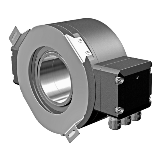
- Seite 1 Montage- und Betriebsanleitung Mounting and operating instructions HMG 161 Absoluter Drehgeber Absolute encoder...
-
Seite 2: Inhaltsverzeichnis
Inhaltsverzeichnis Inhaltsverzeichnis Allgemeine Hinweise ..............................Betrieb in explosionsgefährdeten Bereichen ..................... Sicherheitshinweise ..............................Vorbereitung ..................................Montage ....................................Schritt 1 ..................................Schritt 2 ..................................Schritt 3 ..................................Montagehinweis ..............................Abmessungen ................................SSI/Inkremental ..............................6.2 Profibus (CANopen®, DeviceNet) ....................... 6.3 Profibus (CANopen®, DeviceNet) und SSI/Inkremental ..............Elektrischer Anschluss ............................7.1 Profibus DP V0 .............................. - Seite 3 Table of contents Table of contents General notes ................................... Operation in potentially explosive environments ..................Security indications ..............................Preparation ..................................Mounting .................................... Step 1 ..................................Step 2 ..................................Step 3 ..................................Mounting instruction ............................Dimensions ..................................SSI/incremental ..............................6.2 Profibus (CANopen®, DeviceNet) ......................
-
Seite 4: Allgemeine Hinweise
Allgemeine Hinweise Allgemeine Hinweise Zeichenerklärung: Gefahr Warnung bei möglichen Gefahren Hinweis zur Beachtung Hinweis zur Gewährleistung eines einwandfreien Betriebes des Gerätes Information Empfehlung für die Gerätehandhabung Der absolute Drehgeber HMG 161 ist ein opto-elektronisches Prä zi sionsmessgerät, das mit Sorgfalt nur von technisch qualifiziertem Per s onal gehandhabt werden darf. 1.3 Die zu erwartende Lebensdauer des Gerätes hängt von den Kugellagern ab, die mit einer Dauerschmierung ausgestattet sind. Der Lagertemperaturbereich des Gerätes liegt zwischen -15 °C bis +70 °C. Der Betriebstemperaturbereich des Gerätes liegt zwischen -20 °C bis +85 °C, eingeschränkt im Ex-Bereich, siehe Abschnitt 2, am Gehäuse gemessen. EU-Konformitätserklärung gemäß den europäischen Richtlinien. Das Gerät ist zugelassen nach UL (gilt nicht für Einsatz in explosionsgefährdeten Bereichen). -
Seite 5: General Notes
Symbol guide: Danger Warnings of possible danger General information for attention Informations to ensure correct device operation Information Recommendation for device handling 1.2 The absolute encoder HMG 161 is an opto electro nic precision measurement device which must be handled with care by skilled personnel only. 1.3 The expected service life of the device depends on the ball bearings, which are equipped with a permanent lubrication. The storage temperature range of the device is between -15 °C and +70 °C. The operating temperature range of the device is between -20 °C and +85 °C, restricted in potentially explosive environments, see section 2, measured at the housing. -
Seite 6: Betrieb In Explosionsgefährdeten Bereichen
Betrieb in explosionsgefährdeten Bereichen Betrieb in explosionsgefährdeten Bereichen Das Gerät entspricht der Richtlinie 2014/34/EU für explosionsgefährdete Bereiche. Der Einsatz ist gemäß den Gerätekategorien 3 G (Ex-Atmosphäre Gas) und 3 D (Ex-Atmo- sphäre Staub) zulässig. Gerätekategorie 3 G: - Ex-Kennzeichnung: II 3 G Ex nA IIC T4 Gc - Normenkonformität: EN 60079-0:2012 + A11:2013 EN 60079-15:2010 - Zündschutzart: - Temperaturklasse: - Gerätegruppe: Gerätekategorie 3 D: - Ex-Kennzeichnung: II 3 D Ex tc IIIB T135°C Dc - Normenkonformität: EN 60079-31:2014... -
Seite 7: Operation In Potentially Explosive Environments
Operation in potentially explosive environments Operation in potentially explosive environments The device complies with the directive 2014/34/EU for potentionally explosive atmospheres. It can be used in accordance with equipment categories 3 G (explosive gas atmosphere) and 3 D (explosive dust atmosphere) Equipment category 3 G: - Ex labeling: II 3 G Ex nA IIC T4 Gc - Conforms to standard: EN 60079-0:2012 + A11:2013 EN 60079-15:2010 - Type of protection: - Temperature class: - Group of equipment: Equipment category 3 D: II 3 D Ex tc IIIB T135°C Dc - Ex labeling: - Conforms to standard: EN 60079-31:2014... -
Seite 8: Sicherheitshinweise
Sicherheitshinweise Sicherheitshinweise Verletzungsgefahr durch rotierende Wellen Haare und Kleidungsstücke können von rotierenden Wellen erfasst werden. Vor allen Arbeiten alle Betriebsspannungen ausschalten und Maschinen stillsetzen. • Zerstörungsgefahr durch elektrostatische Aufladung Die elektronischen Bauteile im Gerät sind empfindlich gegen hohe Spannungen. Steckkontakte und elektronische Komponenten nicht berühren. • Ausgangsklemmen vor Fremdspannungen schützen. • Maximale Betriebsspannung nicht überschreiten. • Zerstörungsgefahr durch mechanische Überlastung Eine starre Befestigung kann zu Überlastung durch Zwangskräfte führen. Die Beweglichkeit des Gerätes niemals einschränken. Unbedingt die Montagehinweise beach- • ten. Die vorgegebenen Abstände und/oder Winkel unbedingt einhalten. • Zerstörungsgefahr durch mechanischen Schock Starke Erschütterungen, z. B. Hammerschläge, können zur Zerstörung der Abtastung führen. Niemals Gewalt anwenden. Bei sachgemäßer Montage lässt sich alles leichtgängig zusam- • menfügen. Für die Demontage geeignetes Abziehwerkzeug benutzen. • Zerstörungsgefahr durch Verschmutzung Schmutz kann im Gerät zu Kurzschlüssen und zur Beschädigung der Abtastung führen. -
Seite 9: Security Indications
Security indications Security indications Risk of injury due to rotating shafts Hair and clothes may become tangled in rotating shafts. Before all work switch off all voltage supplies and ensure machinery is stationary. • Risk of destruction due to electrostatic charge Electronic parts contained in the device are sensitive to high voltages. Do not touch plug contacts or electronic components. • Protect output terminals against external voltages. • Do not exceed maximum voltage supply. • Risk of destruction due to mechanical overload Rigid mounting may give rise to constraining forces. Never restrict the freedom of movement of the device. The mounting instructions must be • followed. It is essential that the specified clearances and/or angles are observed. • Risk of destruction due to mechanical shock Violent shocks, e. g. due to hammer impacts, can lead to the destruction of the sensing system. -
Seite 10: Vorbereitung
Vorbereitung / Preparation Vorbereitung Preparation Lieferumfang Grundgerät Scope of delivery of the basic device 8, 9, 10 Gehäuse Housing Durchgehende Hohlwelle Through hollow shaft Statorkupplung Stator coupling Klemmring Clamping ring Klemmringschraube M4x16 mm, ISO 4762 Clamping ring screw M4x16 mm, ISO 4762 Erdungsband ~230 mm lang Earthing strap, length ~230 mm D-SUB Stecker 9-polig am Gerätegehäuse D-SUB connector (male) 9-pin on the device zum Anschluss einer Bushaube, je nach Ver- housing for connecting a bus cover, depending sion, siehe Abschnitt 4.2, 4.3 oder 4.4. on the version, see section 4.2, 4.3 or 4.4. Profibus-Haube , siehe Abschnitt 4.2. Profibus cover , see section 4.2. CANopen®-Haube , siehe Abschnitt 4.3. - Seite 11 Vorbereitung / Preparation Lieferumfang Profibus-Haube Scope of delivery of the profibus cover Profibus-Haube Profibus cover Torx-/Schlitzschraube M4x32 mm (A2) Torx/slotted screw M4x32 mm (A2) Scheibe A4, DIN 137 (A2) Washer A4, DIN 137 (A2) D-SUB Buchse 9-polig zum Anschluss D-SUB connector (female) 9-pin for connec- an D-SUB Stecker 9-polig am tion to the D-SUB connector (male) 9-pin Gerätegehäuse on the device housing Anschlussklemmen, siehe Abschnitt 7.1.2. Connecting terminal, see section 7.1.2. Kabelverschraubung M16x1,5 Cable gland M16x1,5 für Kabel ø5...9 mm for cable ø5...9 mm Lieferumfang CANopen®-Haube Scope of delivery of the CANopen® cover CANopen®-Haube CANopen® cover...
-
Seite 12: Lieferumfang Ssi/Inkremental-Haube Mit Anschlussklemmen
Vorbereitung / Preparation Lieferumfang DeviceNet-Haube Scope of delivery of the DeviceNet cover DeviceNet-Haube DeviceNet cover Torx-/Schlitzschraube M4x32 mm (A2) Torx/slotted screw M4x32 mm (A2) Scheibe A4, DIN 137 (A2) Washer A4, DIN 137 (A2) D-SUB Buchse 9-polig zum Anschluss D-SUB connector (female) 9-pin for connec- an D-SUB Stecker 9-polig am tion to the D-SUB connector (male) 9-pin Gerätegehäuse on the device housing Anschlussklemmen, siehe Abschnitt 7.3.2. Connecting terminal, see section 7.3.2. Kabelverschraubung M16x1,5 Cable gland M16x1,5 für Kabel ø5...9 mm for cable ø5...9 mm Lieferumfang SSI/Inkremental-Haube Scope of delivery of the SSI/incremen- mit Anschlussklemmen tal cover with connecting terminal SSI/Inkremental-Haube... -
Seite 13: Zur Montage Erforderlich
Vorbereitung / Preparation Lieferumfang SSI/Inkremental-Haube Scope of delivery of the SSI/incremen- mit Flanschdose und Rundsteckver- tal cover with flange connector and binder mating connector SSI/Inkremental-Haube SSI/incremental cover Torx-/Schlitzschraube M4x32 mm (A2) Torx/slotted screw M4x32 mm (A2) Scheibe A4, DIN 137 (A2) Washer A4, DIN 137 (A2) Flanschdose M23, 12-polig, Flange connector M23, 12-pin, siehe Abschnitt 7.4.2. see section 7.4.2. Rundsteckverbinder, Mating connector, siehe Abschnitt 7.4.2. see section 7.4.2. Zur Montage erforderlich Required for mounting (nicht im Lieferumfang enthalten) -
Seite 14: Erforderliches Werkzeug
Vorbereitung - Montage / Preparation - Mounting Erforderliches Werkzeug Required tools (nicht im Lieferumfang enthalten) (not included in scope of delivery) 4 mm 4 mm 1,6x8,0 mm 1.6x8.0 mm 17 und 22 mm (24 und 27 mm 17 and 22 mm (24 and 27 mm TX 20 TX 20 Für SSI-Haube mit Rundsteckverbinder For SSI cover with mating connector Werkzeugset als Zubehör erhältlich: Tool kit available as accessory: Bestellnummer 11068265 Order number 11068265 Montage Mounting Schritt 1 Step 1 4 mm * Siehe Seite 7 See page 7 MB115 - 11055726 ... -
Seite 15: Schritt 2
Montage / Mounting Schritt 2 Step 2 * Siehe Seite 7 oder 10 See page 7 or 10 Antriebswelle einfetten. Lubricate drive shaft. Die Antriebswelle sollte einen mög- The drive shaft should have as less lichst kleinen Rundlauffehler aufwei- runout as possible because this can sen, da dieser zu einem Winkelfehler otherwise result in an angle error. -
Seite 16: Schritt 3
Montage / Mounting Schritt 3 Step 3 4 mm Zul. Anzugsmoment Max. tightening torque = 3...4 Nm * Siehe Seite 7 See page 7 Montagehinweis Mounting instruction Wir empfehlen, das Gerät so zu mon- It is recommended to mount the de- tieren, dass der Kabelanschluss kei- vice with cable connection facing nem direkten Wassereintritt ausge- downward and being not exposed to... -
Seite 17: Abmessungen
Abmessungen / Dimensions Abmessungen Dimensions SSI/Inkremental SSI/incremental (74354, 74356) (74354, 74356) ød ød1 Positive Drehrichtung Positive rotating direction 70.5 Profibus (CANopen®, DeviceNet) Profibus (CANopen®, DeviceNet) (74357) (74357) ød ød1 70.5 Positive Drehrichtung Positive rotating direction All dimensions in millimeters (unless otherwise stated) MB115 - 11055726 Baumer_HMG161_II_DE-EN (19A1) ... -
Seite 18: Profibus (Canopen®, Devicenet) Und Ssi/Inkremental
Abmessungen / Dimensions Profibus (CANopen®, DeviceNet) Profibus (CANopen®, DeviceNet) und SSI/Inkremental and SSI/incremental (74349, 74358, 74359) (74349, 74358, 74359) ød ød1 70.5 Positive Drehrichtung Positive rotating direction All dimensions in millimeters (unless otherwise stated) MB115 - 11055726 Baumer_HMG161_II_DE-EN (19A1) -
Seite 19: Elektrischer Anschluss
Elektrischer Anschluss / Electrical connection Elektrischer Anschluss Electrical connection Profibus DP V0 Profibus DP V0 7.1.1 Kabelanschluss 7.1.1 Cable connection Ansicht siehe Abschnitt 7.1.2. TX 20 View see section 7.1.2. 17 mm Kabelschirm Cable shield ø5...9 mm Zul. Anzugsmoment Max. tightening torque = 2...3 Nm * Siehe Seite 7, 8 oder 10 See page 7, 8 or 10 Zur Gewährleistung der angegebenen To ensure the specified protection of Schutzart sind nur geeignete Kabel- the device the correct cable diameter... -
Seite 20: Klemmenbelegung Und Schalterstellung
Elektrischer Anschluss / Electrical connection 7.1.2 Klemmenbelegung und Schalterstellung 7.1.2 Terminal assignment and switch settings Ansicht V Ansicht in Profibus-Haube, siehe Abschnitt 7.1.1. View V View into Profibus cover, see section 7.1.1. Negative serielle Datenleitung, Negative serial data transmis- Paar 1 und Paar 2 sion, pair 1 and pair 2 Positive serielle Datenleitung, Positive serial data transmission, Paar 1 und Paar 2 pair 1 and pair 2 Betriebsspannung Voltage supply 9...30 VDC 9...30 VDC GND Masseanschluss für UB GND Ground connection for UB a) Einstellungen der Abschlusswiderstände a) Settings for the terminating resistors ON = Letzter Teilnehmer Last user... -
Seite 21: Funktionen
Detailed instruction for the Profibus Profibus-DP V0 Schnittstelle und die DP V0 interface and the device de- GSD-Datei finden Sie auf unserer In- scription file GSD can be found on ternetseite www.baumer.com. our website www.baumer.com. MB115 - 11055726 Baumer_HMG161_II_DE-EN (19A1) ... -
Seite 22: Canopen
Elektrischer Anschluss / Electrical connection CANopen® CANopen® 7.2.1 Kabelanschluss 7.2.1 Cable connection Ansicht TX 20 siehe Abschnitt 7.2.2. View see section 7.2.2. 17 mm Kabelschirm Cable shield ø5...9 mm Zul. Anzugsmoment Max. tightening torque = 2...3 Nm * Siehe Seite 7, 8 oder 10 See page 7, 8 or 10 Zur Gewährleistung der angegebenen To ensure the specified protection of Schutzart sind nur geeignete Kabel- the device the correct cable diameter durchmesser zu verwenden. -
Seite 23: Klemmenbelegung Und Schalterstellung
Elektrischer Anschluss / Electrical connection 7.2.2 Klemmenbelegung und Schalterstellung 7.2.2 Terminal assignment and switch settings Ansicht W Ansicht in CANopen® Haube, siehe Abschnitt 7.2.1. View W View into CANopen® cover, see section 7.2.1. c) Siehe Seite 21/See page 21 CAN_L CAN Bus Signal CAN_L CAN Bus signal (dominant Low) (dominant low) CAN_H CAN Bus Signal CAN_H CAN Bus signal (dominant High) (dominant high) Betriebsspannung Voltage supply 9...30 VDC... -
Seite 24: Funktionen
Eine ausführliche Anleitung für die Detailed instruction for the CANo- CANopen® Schnittstelle pen® interface and the device de- EDS-Datei finden Sie auf unserer In- scription file EDS can be found on ternetseite www.baumer.com. our website www.baumer.com. MB115 - 11055726 Baumer_HMG161_II_DE-EN (19A1) -
Seite 25: Devicenet
Elektrischer Anschluss / Electrical connection DeviceNet DeviceNet 7.3.1 Kabelanschluss 7.3.1 Cable connection Ansicht siehe Abschnitt 7.3.2. TX 20 View see section 7.3.2. 17 mm Kabelschirm Cable shield ø5...9 mm Zul. Anzugsmoment Max. tightening torque = 2...3 Nm * Siehe Seite 7, 9 oder 10 See page 7, 9 or 10 Zur Gewährleistung der angegebenen To ensure the specified protection of Schutzart sind nur geeignete Kabel- the device the correct cable diameter durchmesser zu verwenden. -
Seite 26: Klemmenbelegung Und Schalterstellung
Elektrischer Anschluss / Electrical connection 7.3.2 Klemmenbelegung und Schalterstellung 7.3.2 Terminal assignment and switch settings Ansicht X Ansicht in DeviceNet Haube, siehe Abschnitt 7.3.1. View X View into DeviceNet cover, see section 7.3.1. c) Siehe Seite 24/See page 24 CAN_L CAN Bus Signal CAN_L CAN Bus signal (dominant Low) (dominant low) CAN_H CAN Bus Signal CAN_H CAN Bus signal (dominant High) (dominant high) DRAIN Schirmanschluss DRAIN Shield connection Betriebsspannung... -
Seite 27: Funktionen
Detailed instruction for the Device- DeviceNet Schnittstelle und die EDS- Net interface and the device descrip- Datei finden Sie auf unserer Internet- tion file EDS can be found on our seite www.baumer.com. website www.baumer.com. MB115 - 11055726 Baumer_HMG161_II_DE-EN (19A1) ... -
Seite 28: Ssi Und/Oder Inkremental
Elektrischer Anschluss / Electrical connection SSI und/oder Inkremental SSI and/or incremental 7.4.1 Mit Anschlussklemmen 7.4.1 With connecting terminal 7.4.1.1 Kabelanschluss 7.4.1.1 Cable connection TX 20 Zul. Anzugsmoment Max. tightening torque 22 mm = 2...3 Nm Ansicht siehe Abschnitt 7.4.1.2. View see section 7.4.1.2. Kabelschirm Cable shield ø5...13 mm * Siehe Seite 7, 9 oder 10 See page 7, 9 or 10 Zur Gewährleistung der angegebenen To ensure the specified protection of... -
Seite 29: Klemmenbelegung
Elektrischer Anschluss / Electrical connection 7.4.1.2 Klemmenbelegung 7.4.1.2 Terminal assignment Ansicht Y Anschlussklemmen Inkremental, siehe Abschnitt 7.4.1.1. View Y Conneting terminal incremental, see section 7.4.1.1. Nicht benutzen/Do not use Ansicht Y Anschlussklemmen Inkremental und SSI, siehe Abschnitt 7.4.1.1. View Y Conneting terminal incremental and SSI, see section 7.4.1.1. Param Param DATA DATA DATA DATA CLOCK CLOCK CLOCK CLOCK ERROR ERROR Betriebsspannung nicht auf Ausgän- Do not connect voltage supply to ge legen! Zerstörungsgefahr! outputs! Danger of damage! Spannungsabfälle in langen Leitungen... -
Seite 30: Mit Flanschdose Und Rundsteckverbinder
Elektrischer Anschluss / Electrical connection 7.4.2 Mit Flanschdose und Rundsteckverbin- 7.4.2 With flange connector and mating con- nector 7.4.2.1 Kabelanschluss, Schritt 1 7.4.2.1 Cable connection, step 1 ø7...12 mm Kabelschirm Ansicht Cable shield siehe Abschnitt 7.4.2.3. View see section 7.4.2.3. EMV-Ring EMC ring Code 27 mm 12d * 24 mm * Siehe Seite 10 oder 11 See page 10 or 11... -
Seite 31: Kabelanschluss, Schritt
Elektrischer Anschluss / Electrical connection 7.4.2.2 Kabelanschluss, Schritt 2 7.4.2.2 Cable connection, step 2 Ansicht siehe Abschnitt 7.4.2.3. View see section 7.4.2.3. Handfest Hand-tight * Siehe Seite 10 See page 10 7.4.2.3 Pinbelegung 7.4.2.3 Pin assignment Ansicht Z1 Ansicht Z2 Signal Flanschdose 12-polig, Löteinsatz, K2 (B-) Stiftkontakte, linksdrehend, siehe Abschnitt 7.4.2.1. View Z2 siehe Abschnitt 7.4.2.2. -
Seite 32: Ausgangssignale
Elektrischer Anschluss / Electrical connection 7.4.3 Ausgangssignale 7.4.3 Output signals 7.4.3.1 Ausgangstreiber inkremental 7.4.3.1 Incremental line drivers 9...30 VDC 9...30 VDC Signalfolge bei positiver Drehrichtung, siehe Abschnitt 6. Sequence for positive rotating direction, see section 6. 7.4.3.2 SSI-Telegramm (Voreinstellung) 7.4.3.2 SSI telegram (default setting) SSI-Clock / SSI clock 100 kHz - 800 kHz SSI-Daten, Singleturn / SSI data, singleturn 12 13 12µs-30µs Positionsdaten 13 Bit Gray Code, rechtsdrehend* Position data 13 Bit gray code, CW*... -
Seite 33: Hinweis Für Ex-Schutz
Sensorkabel HEK 8 (Zubehör) Sensor cable HEK 8 (accessory) Es wird empfohlen, das Baumer Hübner Baumer Hübner sensor cable HEK 8 is Sensorkabel HEK 8 zu verwenden oder recommended. As a substitute a shielded ersatzweise ein geschirmtes, paarig ver- twisted pair cable should be used. Con- seiltes Kabel. Das Kabel sollte in einem... -
Seite 34: Demontage
Demontage / Dismounting Demontage Dismounting Schritt 1 Step 1 8, 9, 10 8a, 9a, 10a 8b, 9b, 10b TX 20 TX 20 8e, 9e, 10e 17 mm 22 mm Schritt 2 Step 2 * Siehe Seite 7 bis 10 See page 7 up to 10 MB115 - 11055726 Baumer_HMG161_II_DE-EN (19A1) - Seite 35 Demontage / Dismounting Schritt 3 Step 3 4 mm Schritt 4 Step 4 * Siehe Seite 7 See page 7 MB115 - 11055726 Baumer_HMG161_II_DE-EN (19A1) ...
- Seite 36 Demontage / Dismounting Schritt 5 Step 5 MB115 - 11055726 Baumer_HMG161_II_DE-EN (19A1)
-
Seite 37: Zubehör
Zubehör / Accessories Zubehör Accessories Sensorkabel für Drehgeber Sensor cable for encoders • • HEK 8 HEK 8 Werkzeugset: Tool kit: • • Bestellnummer 11068265 Order number 11068265 Digital-Konverter Digital converters • • HEAG 151, HEAG 152 und HEAG 154 HEAG 151, HEAG 152 and HEAG 154 LWL-Übertrager Fiber optic links • • HEAG 172, HEAG 174 und HEAG 176 HEAG 172, HEAG 174 und HEAG 176 Digitaler Drehzahlschalter Digital speed switch • • DS 93 DS 93 Prüfgerät für Drehgeber Analyzer for encoders • •... -
Seite 38: Technische Daten
Technische Daten Technische Daten 10.1 Technische Daten - elektrisch Betriebsspannung: 9...30 VDC • Betriebsstrom ohne Last: ≤100 mA (pro Schnittstelle SSI) • ≤250 mA (pro Schnittstelle Bus) Initialisierungszeit: ≤200 ms nach Einschalten • Schnittstellen: SSI, Profibus-DP V0, CANopen®, DeviceNet • Funktion: Multiturn • Übertragungsrate: 9,6...12000 kBaud (Profibus) • 10...1000 kBaud (CANopen®) 125...500 kBaud (DeviceNet) Profilkonformität: Profibus-DP V0 • CANopen® CiA DSP 406 V 3.0 Device Profile Encoder V 1.0 Teilnehmeradresse: Drehschalter in Bushaube • Schrittzahl je Umdrehung: 8192 / 13 Bit •... -
Seite 39: Technische Daten - Mechanisch
10.2 Technische Daten - mechanisch Baugröße (Flansch): ø160 mm • Wellenart: ø38...70 mm (durchgehende Hohlwelle) • Schutzart DIN EN 60529: IP56 • Betriebsdrehzahl: ≤3500 U/min (mechanisch) • Betriebsdrehmoment typ.: 15 Ncm • Trägheitsmoment Rotor: 28,5 kgcm (ø50) • Zulässige Wellenbelastung: ≤350 N axial • ≤500 N radial Werkstoffe: Gehäuse: Aluminium • Welle: Edelstahl Korrosionsschutz: IEC 60068-2-52 Salzsprühnebel • entspricht Umgebungsbedingungen C4 nach ISO 12944-2 Betriebstemperatur: -20...+85 °C... -
Seite 40: Technical Data
Technical data Technical data 10.1 Technical data - electrical ratings Voltage supply: 9...30 VDC • Consumption w/o load: ≤100 mA (per interface SSI) • ≤250 mA (per interface bus) Initializing time: ≤200 ms after power on • Interfaces: SSI, Profibus-DP V0, CANopen®, DeviceNet • Function: Multiturn • Transmission rate: 9.6...12000 kBaud (Profibus) • 10...1000 kBaud (CANopen®) 125...500 kBaud (DeviceNet) Profile conformity: Profibus-DP V0 • CANopen® CiA DSP 406 V 3.0 Device Profile Encoder V 1.0 Device adress: Rotary switch in bus cover • Steps per turn: 8192 / 13 bit •... -
Seite 41: Technical Data - Mechanical Design
10.2 Technical data - mechanical design Dimensions (flange): ø160 mm • Shaft type: ø38...70 mm (through hollow shaft) • Protection DIN EN 60529: IP 56 • Operating speed: ≤3500 rpm (mechanical) • Operating torque typ.: 15 Ncm • Rotor moment of inertia: 28.5 kgcm (ø50) • Admitted shaft load: ≤350 N axial • ≤500 N radial Materials: Housing: aluminium • Shaft: stainless steel Corrosion protection: IEC 60068-2-52 Salt mist • complies to ambient conditions C4 according to ISO 12944-2 Operating temperature: -20...+85 °C •... -
Seite 42: Eu-Konformitätserklärung
Signature/nom/fonction Baumer_HOGSx_OGSx_AMGx_HMGx_DE-EN-FR_CoC_81201176.docm/kwe Baumer Hübner GmbH P.O. Box 126943 ∙ D-10609 Berlin ∙ Max-Dohrn-Str. 2+4 ∙ D-10589 Berlin Phone +49 (0)30 69003-0 ∙ Fax +49 (0)30 69003-104 ∙ info@baumerhuebner.com ∙ www.baumer.com Sitz der Gesellschaft / Registered Office: Berlin, Germany ∙ Geschäftsführer / Managing Director: Dr. Oliver Vietze, Dr. Johann Pohany Handelsregister / Commercial Registry: AG Charlottenburg HRB 96409 ∙... - Seite 43 MB115 - 11055726 Baumer_HMG161_II_DE-EN (19A1)
- Seite 44 Baumer Hübner GmbH P.O. Box 12 69 43 · 10609 Berlin, Germany Phone: +49 (0)30/69003-0 · Fax: +49 (0)30/69003-104 info@baumerhuebner.com · www.baumer.com/motion Version: 74349, 74354, 74356, 74357, 74358, 74359 MB115 - 11055726 Baumer_HMG161_II_DE-EN (19A1 - 25.02.2019)