Baumer HOGS 75 K Montage- Und Betriebsanleitung

Verwandte Anleitungen für Baumer HOGS 75 K


Inhaltszusammenfassung für Baumer HOGS 75 K
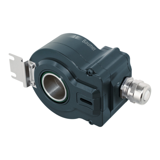
- Seite 1 Montage- und Betriebsanleitung Mounting and operating instructions HOGS 75 K • HOGS 75 KC Sinus Drehgeber mit Anschlusskabel (Rundsteckverbinder) Sine encoder with connecting cable (mating connector)
-
Seite 2: Inhaltsverzeichnis
Inhaltsverzeichnis Inhaltsverzeichnis Allgemeine Hinweise ..............................Betrieb in explosionsgefährdeten Bereichen ..................... Sicherheitshinweise ..............................Vorbereitung ..................................Lieferumfang ................................ Zur Montage erforderlich (nicht im Lieferumfang enthalten) ............Zur Demontage erforderlich (nicht im Lieferumfang enthalten) ..........Erforderliches Werkzeug (nicht im Lieferumfang enthalten) ............Montage ..................................... - Seite 3 Table of contents Table of contents General notes ................................... Operation in potentially explosive environments ..................Security indications ..............................Preparation ..................................Scope of delivery ............................... Required for mounting (not included in scope of delivery) ............Required for dismounting (not included in scope of delivery) ............
-
Seite 4: Allgemeine Hinweise
Information Empfehlung für die Gerätehandhabung Der Sinus Drehgeber HOGS 75 K ist ein opto-elektronisches Prä zi sionsmessgerät, das mit Sorgfalt nur von technisch qualifiziertem Per sonal gehandhabt werden darf. Die zu erwartende Lebensdauer des Gerätes hängt von den Kugellagern ab, die mit einer Dauerschmierung ausgestattet sind. -
Seite 5: General Notes
Information Recommendation for device handling The sine encoder HOGS 75 K is an opto electro nic precision measurement device which must be handled with care by skilled personnel only. The expected service life of the device depends on the ball bearings, which are equipped with a permanent lubrication. -
Seite 6: Betrieb In Explosionsgefährdeten Bereichen
Betrieb in explosionsgefährdeten Bereichen Betrieb in explosionsgefährdeten Bereichen Das Gerät entspricht der Richtlinie 2014/34/EU für explosionsgefährdete Bereiche. Der Einsatz ist gemäß den Gerätekategorien 3 G (Ex-Atmosphäre Gas) und 3 D (Ex-Atmo- sphäre Staub) zulässig. Gerätekategorie 3 G: - Ex-Kennzeichnung: II 3 G Ex nA IIC T4 Gc - Normenkonformität: EN 60079-0:2012 + A11:2013 EN 60079-15:2010... -
Seite 7: Operation In Potentially Explosive Environments
Operation in potentially explosive environments Operation in potentially explosive environments The device complies with the directive 2014/34/EU for potentionally explosive atmospheres. It can be used in accordance with equipment categories 3 G (explosive gas atmosphere) and 3 D (explosive dust atmosphere). Equipment category 3 G: II 3 G Ex nA IIC T4 Gc - Ex labeling:... -
Seite 8: Sicherheitshinweise
Sicherheitshinweise Sicherheitshinweise Verletzungsgefahr durch rotierende Wellen Haare und Kleidungsstücke können von rotierenden Wellen erfasst werden. • Vor allen Arbeiten alle Betriebsspannungen ausschalten und Maschinen stillsetzen. Zerstörungsgefahr durch elektrostatische Aufladung Die elektronischen Bauteile im Gerät sind empfindlich gegen hohe Spannungen. • Steckkontakte und elektronische Komponenten nicht berühren. •... -
Seite 9: Security Indications
Security indications Security indications Risk of injury due to rotating shafts Hair and clothes may become tangled in rotating shafts. • Before all work switch off all voltage supplies and ensure machinery is stationary. Risk of destruction due to electrostatic charge Electronic parts contained in the device are sensitive to high voltages. -
Seite 10: Vorbereitung
Vorbereitung / Preparation Vorbereitung Preparation Lieferumfang Scope of delivery Gehäuse Housing Konuswelle mit Schlüsselfläche SW 17 mm Cone shaft with spanner flat 17 mm a/f Stützblech für Drehmomentstütze Support plate for torque arm Abdeckhaube Cover Torxschraube M3x12 mm Torx screw M3x12 mm Erdungsband ~195 mm lang Earthing strap, length ~195 mm Kabelverschraubung M16x1,5 mm Cable gland M16x1.5 mm für Kabel ø5...9 mm... -
Seite 11: Zur Montage Erforderlich (Nicht Im Lieferumfang Enthalten)
Vorbereitung / Preparation Zur Montage erforderlich Required for mounting (nicht im Lieferumfang enthalten) (not included in scope of delivery) 11b 11c 3x 3x Drehmomentstütze, als Zubehör erhältlich: Torque arm, available as accessory: Bestellnummer Länge L, Version Order number Length L, version 11043628 67...70 mm, Standard 11043628 67...70 mm, standard... -
Seite 12: Zur Demontage Erforderlich (Nicht Im Lieferumfang Enthalten)
Vorbereitung / Preparation Zur Demontage erforderlich Required for dismounting (nicht im Lieferumfang enthalten) (not included in scope of delivery) Montage-/Demontageset als Zubehör erhältlich: Mounting/dismounting set available as accessory: Bestellnummer 11077087, bestehend aus: Order number 11077087, including: Gewindestift M6x10 mm, ISO 7436 Setscrew M6x10 mm, ISO 7436 Abdrückschraube M8x45 mm, ISO 4762 Jack screw M8x45 mm, ISO 4762 Erforderliches Werkzeug... -
Seite 13: Montage
Montage / Mounting Montage Mounting Schritt 1 Step 1 10 mm 10 mm Schritt 2 Step 2 TX 10 * Siehe Seite 7 oder 8 See page 7 or 8 MB175aT1 - 11173568 Baumer_HOGS75K-A-T1_II_DE-EN (19A1) ... -
Seite 14: Schritt 3
Montage / Mounting Schritt 3 Step 3 Zentrierbohrung Center hole DIN 332-D, M6x16 mm 1:10 Antriebswelle einfetten. Lubricate drive shaft. Die Antriebswelle sollte einen mög- The drive shaft should have as less lichst kleinen Rundlauffehler aufwei- runout as possible because this can sen, da dieser zu einem Winkelfehler otherwise result in an angle error, see führen kann, siehe Abschnitt 5.7. -
Seite 15: Schritt 4
Montage / Mounting Schritt 4 Step 4 Zul. Anzugsmoment: Max tightening torque: = 3...4 Nm 17 mm 5 mm 10 mm 1.6x8 mm * Siehe Seite 7 oder 8 See page 7 or 8 MB175aT1 - 11173568 Baumer_HOGS75K-A-T1_II_DE-EN (19A1) ... -
Seite 16: Schritt 5
Montage / Mounting Schritt 5 Step 5 TX 10 Zul. Anzugsmoment Max. tightening torque = 1.2 Nm Sensorkabelbelegung HEK 8 oder HEK 8 HQ, siehe Abschnitt 7.3 oder 7.4. Sensor cable assignment HEK 8 or HEK 8 HQ, see section 7.3 or 7.4. Ansicht Binder-Rundsteckverbinder, siehe Abschnitt 7.5. -
Seite 17: Schritt 6 - Drehmomentstütze
Montage / Mounting Schritt 6 - Drehmomentstütze Step 6 - Torque arm Die Montage der Drehmomentstütze The torque arm should be mounted sollte spielfrei erfolgen. Ein Spiel von free from clearance. A play of just beispielsweise ±0,03 mm entspricht ±0.03 mm, results in a runout of the einem Rundlauffehler des Gerätes von device of 0.06 mm. -
Seite 18: Hinweis Zur Vermeidung Von Messfehlern
Montage / Mounting Hinweis zur Vermeidung von Messfehlern How to prevent measurement errors Für einen einwandfreien Betrieb des To ensure that the device operates cor- Gerätes ist eine korrekte Montage, ins- rectly, it is necessary to mount it accurately besondere auch der Drehmomentstütze, as described in section 5.1 to 5.6, which in- notwendig, wie beschrieben in Abschnitt cludes correct mounting of the torque arm. -
Seite 19: Montagehinweis
Montage / Mounting Montagehinweis Mounting instruction Wir empfehlen, das Gerät so zu mon- It is recommended to mount the de- tieren, dass der Kabelanschluss kei- vice with cable connection facing nem direkten Wassereintritt ausge- downward and being not exposed to setzt ist. -
Seite 20: Abmessung
Abmessung / Dimension Abmessung Dimension (73294, 73295) (73294, 73295) Zubehör Accessory Positive Drehrichtung Positive rotating direction Alle Abmessungen in Millimeter (wenn nicht anders angegeben) All dimensions in millimeters (unless otherwise stated) MB175aT1 - 11173568 Baumer_HOGS75K-A-T1_II_DE-EN (19A1) -
Seite 21: Elektrischer Anschluss
Elektrischer Anschluss / Electrical connection Elektrischer Anschluss Electrical connection Beschreibung der Anschlüsse Terminal significance Betriebsspannung +UB; + Voltage supply Masseanschluss ; ; GND; 0V Ground Erdungsanschluss (Gehäuse) Earth ground (housing) Ausgangssignal Kanal 1 K1; A; A+ Output signal channel 1 Ausgangssignal Kanal 1 invertiert K1;...