Herunterladen Inhalt Inhalt Diese Seite drucken
Inhaltsverzeichnis

Werbung

Verfügbare Sprachen
  • DE

Verfügbare Sprachen

  • DEUTSCH, seite 1
Pumpfix S
Pumpfix S
Einbau- und Betriebsanleitung
2019/12
016-169_01

Werbung

Inhaltsverzeichnis
loading

Inhaltszusammenfassung für Kessel Pumpfix S

  • Seite 1 Pumpfix S Pumpfix S Einbau- und Betriebsanleitung Einbau- und Betriebsanleitung 2019/12 016-169_01...
  • Seite 2: Inhaltsverzeichnis

    Inhalt Liebe Kundin, lieber Kunde, als Premiumhersteller von innovativen Produkten für die Hinweise zu dieser Anleitung........Entwässerungstechnik bietet KESSEL ganzheitliche Sys- Sicherheit..............temlösungen und kundenorientierten Service. Dabei stel- Technische Daten............ len wir höchste Qualitätsstandards und setzen konsequent auf Nachhaltigkeit - nicht nur bei der Herstellung unserer Montage..............
  • Seite 3: Hinweise Zu Dieser Anleitung

    Um die dauerhafte Sicherheit der Anlage zu gewährleisten, Variante oder Zusatzinformation dürfen ausschließlich folgende Tätigkeiten entsprechend der Kursivschreibung (z. B. gilt nur für ATEX-Variante) Qualifikation der ausführenden Person durchgeführt werden. Technische Hinweise, die beson- ders beachtet werden müssen. 016-169_01 Pumpfix S 3 / 140...
  • Seite 4: Bestimmungsgemäße Verwendung

    830075 Verlängerungs- vertiefter Einbau in eine chemikalienresistente Sonderlösung bezogen werden stück mit Flansch, WU-Beton (individual@kessel.de). Um Frostsicherheit zu gewährleis- Gegenflasch ten, muss die Anlage im Gebäude verbaut werden. und elastomerer Die Anlage enthält einen Rückstauverschluss Typ 5. Lau- Sperrbahn fen die Wasserverbraucher während des Rückstaus, wird...
  • Seite 5 Hinweis zur Gewährleistung Es darf nur für das Produkt vorgesehenes KESSEL- Zubehör verwendet werden. Bei Veränderungen am Pro- dukt oder der Verwendung von nicht-originalem Zubehör erlischt die Gewährleistung. 016-169_01 Pumpfix S 5 / 140...
  • Seite 6 6 / 140 Pumpfix S 016-169_01...
  • Seite 7 Einbauvorschlag Schwarze Wanne Bodenaufbau Schwarze Wanne Fliesen Betonboden Estrich Abdichtung Dämmung Sauberkeitsschicht Pumpfix S Verlängerungsstück mit Flansch Art.Nr. 830073 Verlängerungsstück Art.Nr. 830070 016-169_01 Pumpfix S 7 / 140...
  • Seite 8 Einbauvorschlag Weiße Wanne Bodenaufbau Weiße Wanne Fliesen Dämmung Verbundabdichtung Perimeterdämmung Estrich Sauberkeitsschicht Pumpfix F Verlängerungsstück mit WU-Flansch Art.Nr. 830075 8 / 140 Pumpfix S 016-169_01...
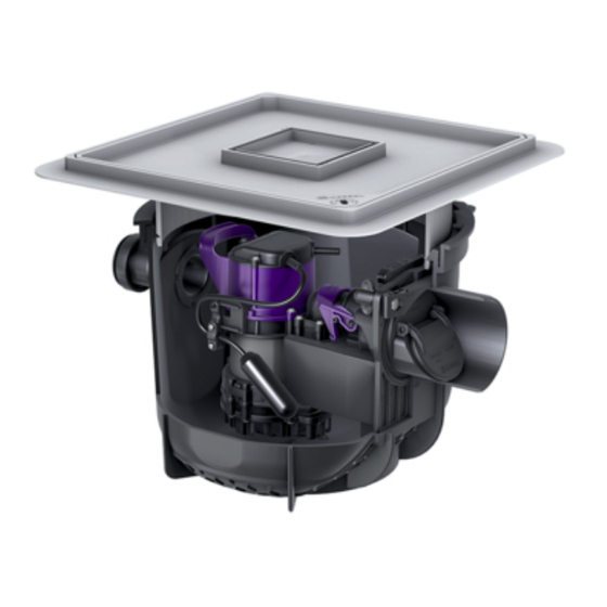
  • Seite 9: Produktbeschreibung

    Rückstau selbsttätig schließen. Im Normalzustand erfolgt die Entwässerung über das natür- liche Gefälle zum Kanal. Die Entwässerung während der Rückstauphase erfolgt über die integrierte Pumpe gegen den Rückstaudruck direkt in den Abwasserkanal. Abb. 1: Lieferumfang 016-169_01 Pumpfix S 9 / 140...
  • Seite 10: Technische Daten

    2,5 A Förderhöhe max. 8m Förderleistung 10 m Schutzart (Pumpe) IP 68 (3mWS) Erforderliche Absicherung C16 A 30 mA Technische Daten Behälter/Hydraulik Belastungsklasse Grundwasserbeständig- 3000 mm keit ab Unterkante Behälter Freier Kugeldurchgang 10 mm 10 / 140 Pumpfix S 016-169_01...
  • Seite 11: Montage

    Optional kann das Auf- satzstück entsprechend gekürzt werden. Aufsatzstück und Abdeckplatte probeweise montieren. Abdeckplatte dient zugleich als Bauzeitenschutz. Um eine leichtere Montage des Aufsatzstückes sicherzu- stellen, Profil-Lippendichtung ausreichend mit Armaturen- fett schmieren. 016-169_01 Pumpfix S 11 / 140...
  • Seite 12: Vertiefter Einbau

    Pumpe) auszuführen. So sind im Wartungs- und Servicefall die notwendigen Teile erreichbar. Gegenstück des Stutzens von innen in die vorgebohrte Öffnung einführen. Stutzen auf Gegenstück handfest aufdrehen, sodass Dichtheit gewährleistet ist. Rohrleitung einschieben. Für weitere Rohrleitungen diese Handlungschritte erneut ausführen. 12 / 140 Pumpfix S 016-169_01...
  • Seite 13 Bohrungen für Dichtun- gen zur Rohrdurchführung dürfen (bis zur abgebildeten Größe) auch an gerundeten Flächen durchgeführt wer- den. KESSEL-Sägeglocke (Art.Nr. 500101) oder gleichwertig zum Bohren der zusätzlichen Leitungen verwenden. Ggf. zusätzliche Leitungen bohren/montieren (max. DN70) Rohrleitungen nur so tief einschieben, dass Funktionsein- Zusätzliche Anschlüsse (zusätzliche Zuläufe, Kabelleer-...
  • Seite 14: Montage Klappengehäuse

    Montage Klappengehäuse Klappengehäuse mit Unterkante voraus einhängen, dann auf Gewinde hochklappen. Unterlegscheiben und Flügelmuttern auf Gewinde auf- schieben, dann festdrehen. Schnellverschluss hochklappen. Anschluss an Grundsammel-Leitung Anschluss zur Grundsammel-Leitung (DN100) herstellen. 14 / 140 Pumpfix S 016-169_01...
  • Seite 15: Pumpe Montieren

    Wird die maximale Kürzung überschritten oder die Mindestüberdeckung nicht eingehalten, ist die Dicht- heit des Behälters nicht gewährleistet. Aufsatzstück montieren (Auflagepunkte berücksichti- gen) und ausrichten. Ein Neigungswinkel von bis zu 5° ist zulässig. 016-169_01 Pumpfix S 15 / 140...
  • Seite 16: Dichtheitsprüfung

    Dem Behälter klares Wasser zuführen, bis die Oberkante des Behälters (nicht des Aufsatzstückes) erreicht ist. Prüfen, ob an einem der Anschlüsse Feuchtigkeit austritt. Wasser abpumpen. Dichtheitsprüfung Sicherstellen, dass Anlage stromlos ist. 16 / 140 Pumpfix S 016-169_01...
  • Seite 17: Inbetriebnahme

    ✓ Mit dem Anschließen der Anschlussleitung(en) an die ✓ Hebel für Notverschluss rastet hörbar aus. Stromversorgung ist die Anlage eingeschaltet. Hebel für Notverschluss bis zum Anschlag umlegen. ✓ Notverschluss ist geschlossen. Der Durchfluss von Abwasser wird in beide Richtungen verhindert. 016-169_01 Pumpfix S 17 / 140...
  • Seite 18: Wartung

    Betätigen des Notverschlusses (schließen und wieder öff- nen) zu überprüfen. Vorbereitung der Wartung Lock & Lift System durch Drehung des Schlüssels entrie- geln. ✓ Abdeckplatte wird durch Drehung angehoben. Abdeckplatte herausheben. Schnellverschluss am Klappengehäuse öffnen. Pumpe herausheben. 18 / 140 Pumpfix S 016-169_01...
  • Seite 19: Wartung Pumpe

    Wartung weiterer Anlagenkomponenten Beide Flügelmuttern des Klappengehäuses abschrauben. Klappengehäuse mit Rückstauklappen abziehen. Klappengehäuse und Rückstauklappen in Wasserbad tauchen. Ggf. Komponente zusätzlich reinigen. Behälter mit Nasssauger aussaugen, dann Behälter (innen) mit feuchtem Lappen reinigen. 016-169_01 Pumpfix S 19 / 140...
  • Seite 20 Komponenten in umgekehrter Reihenfolge wieder zusam- menbauen. Prüfen, ob Schwimmerschalter frei nach unten hängt. Stromanschluss wiederherstellen. Prüfen, ob Anlage anläuft. 20 / 140 Pumpfix S 016-169_01...
  • Seite 21: Hilfe Bei Störungen

    Seite 19) Ansaugkorb verstopft Wartung durchführen (siehe "Wartung Pumpe", Seite 19) Verminderte Verschleiß des Spiralgehäuses Spiralgehäuse auswechseln Förderleistung Verschleiß des Freistromrades Freistromrad auswechseln Entlüftungsöffnung verstopft Entlüftungsöffnung reinigen Überflutung Notverschluss in geschlossener Position Notverschluss öffnen 016-169_01 Pumpfix S 21 / 140...
  • Seite 22 22 / 140 Pumpfix S 016-169_01...
  • Seite 23 Pumpfix S Pumpfix S Installation and operating manual Installation and operating manual 2019/12 016-169_01...
  • Seite 24 Contents Dear customer, As a premium manufacturer of innovative products for drain- Notes on this manual..........ing technology, KESSEL offers integrated system solutions Safety............... and customer-oriented service. In doing so, we set the high- Technical data............est quality standards and focus firmly on sustainability - not only with the manufacturing of our products, but also with Installation..............
  • Seite 25: Notes On This Manual

    Italics applicable only for ATEX variants) with the qualification of the person carrying out the activity. Technical information or instructions which must be paid particular attention. 016-169_01 Pumpfix S 25 / 140...
  • Seite 26: Intended Use

    Condensate from condensing boilers must be neutralised or diluted. Alternatively, a chemical-resistant customised 830075 Extension sec- Deeper installation solution can be purchased (individual@kessel.de). The sys- tion with flange, in waterproof con- tem must be installed in a building to guarantee frost protec- counter-flange crete tion.
  • Seite 27 Note on warranty Only KESSEL accessories designed for the product may be used. If any modifications are made to the product or non-original accessories are used, the warranty becomes null and void. 016-169_01 Pumpfix S 27 / 140...
  • Seite 28 28 / 140 Pumpfix S 016-169_01...
  • Seite 29 Installation suggestion black tank Floor structure black tank Tiles Concrete floor Screed Waterproofing layer Insulation Clean layer Pumpfix S Extension section with flange art. no. 830073 Extension section art. no. 830070 016-169_01 Pumpfix S 29 / 140...
  • Seite 30 Installation suggestion white tank Floor structure white tank Tiles Insulation Waterproofing layer Perimeter insulation Screed Clean layer Pumpfix F Extension section with water- proof flange art. no. 830075 30 / 140 Pumpfix S 016-169_01...
  • Seite 31: Product Description

    Normally, draining takes place via the natural slope to the sewer. During the backwater phase, draining takes place via the integrated pump against backwater pressure directly into the sewage channel. Fig. 1: Scope of delivery 016-169_01 Pumpfix S 31 / 140...
  • Seite 32: Technical Data

    10 m Protection class (pump) IP 68 (3mWS) Required protection C16 A 30 mA Technical data system tank/hydraulic system Load class Groundwater resistant from 3000 mm lower edge of system tank Free passage 10 mm 32 / 140 Pumpfix S 016-169_01...
  • Seite 33: Installation

    Trial-fit upper section and cover plate. The cover plate also provides protection during the con- struction period. To guarantee easier fitting of the upper section, grease the profile lip seal sufficiently with fittings grease. 016-169_01 Pumpfix S 33 / 140...
  • Seite 34: Connecting The Pipes

    Insert the socket mating part into the pre-drilled opening tenance and servicing. from the inside. Screw the socket hand-tight onto the mating part so that tightness is guaranteed. Push the pipe in. Carry out these steps again for further pipes. 34 / 140 Pumpfix S 016-169_01...
  • Seite 35 (up to the size illustrated) may also be drilled on rounded surfaces. Use the KESSEL hole saw (art. no. 500101) or equivalent to drill holes for the additional pipes. Only push the pipes in to such an extent that functional Drill/fit additional pipes (max.
  • Seite 36 Slide the washers and wing nuts onto the threads, then screw them tight. Lift the quick-release closure. Connection to the basic collecting pipe Establish a connection to the basic connection pipe (DN100). 36 / 140 Pumpfix S 016-169_01...
  • Seite 37: Installing The Pump

    Fit the upper section (take the contact points into account) and align. An angle of inclination of up to 5° is permissi- ble. 016-169_01 Pumpfix S 37 / 140...
  • Seite 38 (not of the upper section). Check whether humidity is escaping at one of the connec- tions. Pump the water out. Leak test Make sure that the system is currentless. 38 / 140 Pumpfix S 016-169_01...
  • Seite 39: Commissioning

    ✓ The lever for the emergency closure can be heard to dis- engage. Turn the lever for emergency closure as far as it will go. ✓ The emergency closure is closed. The flow of wastewater is prevented in both directions. 016-169_01 Pumpfix S 39 / 140...
  • Seite 40: Maintenance

    Unlock the Lock & Lift system by turning the key. ✓ Cover plate is lifted by turning. Lift out the cover plate. Open the quick-release closure on the flap housing. Lift the pump out. 40 / 140 Pumpfix S 016-169_01...
  • Seite 41: Pump Maintenance

    Submerse the flap housing and backwater flaps in a water bath. If necessary, perform additional component clean- ing. Vacuum out system tank with wet vacuum cleaner and then clean system tank (interior) with damp cloth. 016-169_01 Pumpfix S 41 / 140...
  • Seite 42 Assemble the components again in reverse order. Check whether the float switch is hanging down freely. Connect to the power supply again. Check if the system is running. 42 / 140 Pumpfix S 016-169_01...
  • Seite 43: Troubleshooting

    41) Reduced pump- Spiral housing is worn Replace spiral housing ing capacity Multi-vane impeller is worn Replace multi-vane impeller Ventilation pipe blocked Clean ventilation pipe Flooding Emergency closure in closed position Open emergency closure 016-169_01 Pumpfix S 43 / 140...
  • Seite 44 44 / 140 Pumpfix S 016-169_01...
  • Seite 45 Pumpfix S Pumpfix S Instructions de pose et d’utilisation Instructions de pose et d’utilisation 2019/12 016-169_01...
  • Seite 46 Sommaire Chère cliente, cher client, En qualité de producteur de pointe de produits novateurs Informations spécifiques aux présentes instruc- dans le domaine de la technique d’assainissement, KESSEL tions................. propose des réponses systématiques globales et un ser- Sécurité..............vice orienté aux besoins de la clientèle. Nous misons simul- Caractéristiques techniques........
  • Seite 47: Informations Spécifiques Aux Présentes Instructions

    Variante ou informations complé- tion requise sont autorisées à travailler sur le système. Caractères italiques mentaires (par exemple, unique- ment valable pour la variante ATEX) informations techniques à observer en particulier. 016-169_01 Pumpfix S 47 / 140...
  • Seite 48: Utilisation Conforme À L'usage Prévu

    Personne Activités autorisées sur les systèmes KESSEL Exploitant Contrôle visuel Personne qualifiée (connaît et com- Vidange, nettoyage (inté- prend les instructions d’utilisation) rieur) contrôle fonctionnel Technicien qualifié (confor- Pose, remplacement, maintenance des compo- mément aux instructions de sants, raccordement au secteur, mise en service pose et normes d’exécution)
  • Seite 49 Remarque concernant la garantie Utiliser uniquement les accessoires prévus pour le produit KESSEL. Le fabricant décline tout recours à sa garantie en cas de modifications effectuées sur le produit ou de l’utilisation d’accessoires non originaux. 016-169_01 Pumpfix S 49 / 140...
  • Seite 50 50 / 140 Pumpfix S 016-169_01...
  • Seite 51 Suggestion de montage d’une cuve noire Schéma du sol d’une cuve noire Carrelage Sol en béton Chape Étanchéité Isolation Couche de mise à niveau Pumpfix S Rallonge de rehausse avec bride, réf. 830073 Rallonge de rehausse, réf. 830070 016-169_01 Pumpfix S 51 / 140...
  • Seite 52 Suggestion de montage d’une cuve blanche Schéma du sol d’une cuve blanche Carrelage Isolation Joint composite Isolation périphérique Chape Couche de mise à niveau Pumpfix F Rallonge de rehausse avec bride de béton étanche, réf. 830075 52 / 140 Pumpfix S 016-169_01...
  • Seite 53: Description Du Produit

    L’écoulement pendant la phase de mise en charge se produit via la pompe intégrée contre la pres- sion de reflux directe dans la canalisation des eaux d'égout. Fig. 1: Détail de livraison 016-169_01 Pumpfix S 53 / 140...
  • Seite 54: Caractéristiques Techniques

    Puissance de refoulement 10 m IP 68 (3 m/ Catégorie de protection (pompe) colonne d'eau) Protection par fusible nécessaire C16 A 30 mA Caractéristiques techniques de la cuve / des composants hydrauliques Classe de charge 54 / 140 Pumpfix S 016-169_01...
  • Seite 55 016-169_01 Pumpfix S 55 / 140...
  • Seite 56: Montage

    Le couvercle de protection sert également de protection de chantier. Il est recommandé, afin de faciliter le montage de la rehausse, d’appliquer une couche de graisse pour robi- netteries sur le joint à lèvres profilé. 56 / 140 Pumpfix S 016-169_01...
  • Seite 57 Introduire le pendant du manchon de l’intérieur dans l’ori- nance et du SAV. fice prépercé. Visser le manchon sur le pendant à la main de sorte à garantir l’étanchéité. Raccordement de la canalisation. Répéter ces étapes pour d’autres canalisations. 016-169_01 Pumpfix S 57 / 140...
  • Seite 58 çages destinés aux joints d’étanchéité pour passage de tuyau (jusqu’à la taille indiquée) sont également permis sur des surfaces arrondies. Utiliser la scie cloche KESSEL (réf. 500101) ou un outil de ce type pour le perçage des conduites supplémen- Si nécessaire, percer/monter des conduites supplémen- taires.
  • Seite 59 Glisser les rondelles et les écrous papillons sur les file- tages, et visser à bloc. Replier la fermeture rapide vers le haut. Raccordement à la conduite de base Établir les raccordements à la conduite de base (DN100). 016-169_01 Pumpfix S 59 / 140...
  • Seite 60: Montage De La Pompe

    Monter la rehausse (tenir compte des points d'appui) et la mettre à niveau. Un angle d'inclinaison de jusqu'à 5° est admissible. 60 / 140 Pumpfix S 016-169_01...
  • Seite 61 Amener de l’eau claire dans la cuve jusqu’au bord supé- rieur de la cuve (et non jusqu’au bord supérieur de la rehausse). Vérifier l'absence de fuite au niveau des raccordements. Refouler l’eau. Essai d'étanchéité S'assurer que le système est hors tension. 016-169_01 Pumpfix S 61 / 140...
  • Seite 62: Mise En Service

    ✓ Le désenclenchement du levier du verrouillage d'urgence est audible. Renverser le levier du verrouillage d'urgence jusqu’en butée. ✓ Le verrouillage d'urgence est fermé. L’écoulement des eaux usées est empêché dans les deux directions. 62 / 140 Pumpfix S 016-169_01...
  • Seite 63: Maintenance

    Déverrouiller le système Lock & Lift en tournant la clé. ✓ La rotation a pour effet de soulever le couvercle de pro- tection. Extraire le couvercle de protection. Ouvrir la fermeture rapide du corps de clapet. Extraire la pompe. 016-169_01 Pumpfix S 63 / 140...
  • Seite 64 Dévisser les deux écrous à ailettes du corps de clapet. Retirer le corps de clapet avec le clapet antiretour. Immerger le corps de clapet et les clapets antiretours dans un bain-marie. Si nécessaire, nettoyer également les autres composants. 64 / 140 Pumpfix S 016-169_01...
  • Seite 65 à eau, puis essuyer la cuve (à l’intérieur) avec un chiffon humide. Remonter les composants dans le sens inverse du démontage. S'assurer que l’interrupteur à flotteur est sus- pendu librement vers le bas. Rétablir l’alimentation en tension. Vérifier que le système démarre. 016-169_01 Pumpfix S 65 / 140...
  • Seite 66: Aide En Cas De Panne

    Déclenchement du fusible principal Réactiver le fusible Cordon d'alimentation défectueux Réparation par un électricien qualifié / un parte- Pompe ne fonc- naire de SAV de KESSEL tionne pas Flotteur défectueux Informer le service après-vente si nécessaire Surchauffe La pompe submersible se remet automatique- ment en marche après la chute de la tempéra-...
  • Seite 67 016-169_01 Pumpfix S 67 / 140...
  • Seite 68 Pumpfix S Pumpfix S Istruzioni per l’installazione e l’uso Istruzioni per l’installazione e l’uso 2019/12 016-169_01...
  • Seite 69 Cara cliente, caro cliente, in qualità di produttore premium di prodotti innovativi per la Indicazioni sulle presenti istruzioni......tecnica di drenaggio, KESSEL offre soluzioni di sistema inte- Sicurezza..............grate e un servizio orientato al cliente. Puntiamo sui mas- Dati tecnici...............
  • Seite 70: Indicazioni Sulle Presenti Istruzioni

    Variante o informazione supple- rispetto della qualifica della persona esecutrice. mentare (ad esempio in caso di Corsivo validità per la sola variante ATEX) Avvertenza tecnica che richiede particolare attenzione. 70 / 140 Pumpfix S 016-169_01...
  • Seite 71: Uso Conforme Alla Destinazione

    In alternativa è possibile ottenere anche una soluzione speciale resistente 830075 Prolunga con flan- Installazione più alle sostanze chimiche (individual@kessel.de). Per garantire gia, contro-flangia profonda nel cal- la sicurezza antigelo, l’impianto deve essere installato nell’e- e nastro di erme- cestruzzo imp.
  • Seite 72 Indicazione sulla garanzia È possibile utilizzare solo gli accessori KESSEL previsti per il prodotto. Le modifiche al prodotto o l’uso di acces- sori non originali annullano la garanzia. 72 / 140 Pumpfix S 016-169_01...
  • Seite 73 016-169_01 Pumpfix S 73 / 140...
  • Seite 74 Suggerimento di installazione “vasca nera” Montaggio nel pavimento “vasca nera” Piastrelle Pavimento in calce- struzzo Massetto Tenuta Isolamento Strato di protezione Pumpfix S Prolunga con flangia cod.art. 830073 Prolunga cod.art. 830070 74 / 140 Pumpfix S 016-169_01...
  • Seite 75 Suggerimento di installazione “vasca bianca” Montaggio nel pavimento “vasca bianca” Piastrelle Isolamento Tenuta Isolamento perime- trale Massetto Strato di protezione Pumpfix F Prolunga con flangia impermeabile cod.art. 830075 016-169_01 Pumpfix S 75 / 140...
  • Seite 76: Descrizione Del Prodotto

    In condizioni normali, il drenaggio avviene tramite la natu- rale pendenza verso la canalizzazione. Il drenaggio durante la fase di ristagno avviene tramite la pompa integrata contro la pressione del ristagno direttamente nella canalizzazione delle acque di scarico. Fig. 1: In dotazione 76 / 140 Pumpfix S 016-169_01...
  • Seite 77: Dati Tecnici

    IP 68 (3 mH2O) Protezione necessaria C16 A 30 mA Dati tecnici del contenitore/dati idraulici Classe di carico Resistenza all’acqua freatica dal 3000 mm bordo inferiore del contenitore Passaggio della canalizzazione libero 10 mm 016-169_01 Pumpfix S 77 / 140...
  • Seite 78: Montaggio

    La piastra di copertura funge anche da copertura protet- tiva da cantiere. Per garantire un montaggio semplice del rialzo, la guar- nizione a labbro profilata va ingrassata sufficientemente con del grasso per valvole. 78 / 140 Pumpfix S 016-169_01...
  • Seite 79: Collegamento Delle Tubazioni

    Inserire il contropezzo del bocchettone nell’apertura previ- sta dall’interno. Serrare manualmente il bocchettone sul contropezzo, in modo da garantire la tenuta. Inserire le tubazioni. Ripetere questi passaggi per delle altre tubazioni. 016-169_01 Pumpfix S 79 / 140...
  • Seite 80 (vedere la figura). I fori per le guarnizioni per il passante tubi possono essere praticati anche sulle superfici arrotondate (fino alla misura illustrata). Usare la sega a tazza KESSEL (cod.art. 500101) o un utensile analogo per praticare i fori per i condotti supple- mentari.
  • Seite 81 Spingere le rondelle e i dadi a farfalla sulle filettature e, quindi, avvitarli saldamente. Sollevare lo sgancio rapido. Allacciamento al collettore principale Realizzare il collegamento al collettore principale (DN 100). 016-169_01 Pumpfix S 81 / 140...
  • Seite 82: Montaggio Della Pompa

    Se l’accorciamento massimo è superato o la copertura minima non è rispettata, la tenuta del conteni- tore non è garantita. Montare e orientare il rialzo (tenendo conto dei punti d’ap- poggio). È ammesso un angolo di inclinazione fino a 5°. 82 / 140 Pumpfix S 016-169_01...
  • Seite 83: Prova Di Tenuta

    Riempire il contenitore di acqua pulita fino a raggiungere il bordo superiore del contenitore stesso (non del rialzo). Controllare se da uno dei collegamenti fuoriesce dell’umi- dità. Pompare via l’acqua. Prova di tenuta Accertare che l’apparecchio sia privo di corrente. 016-169_01 Pumpfix S 83 / 140...
  • Seite 84: Messa In Funzione

    ✓ La leva della chiusura di emergenza si sblocca in modo udibile. Ribaltare la leva della chiusura di emergenza fino all’arre- sto. ✓ La chiusura di emergenza è chiusa. Il flusso delle acque di scarico è impedito in entrambe le direzioni. 84 / 140 Pumpfix S 016-169_01...
  • Seite 85: Manutenzione

    Preparazione della manutenzione Sbloccare il sistema Lock & Lift ruotando la chiave. ✓ La piastra di copertura viene sollevata tramite rotazione. Togliere la piastra di copertura. Aprire lo sgancio rapido sull’alloggiamento della cerniera. Togliere la pompa. 016-169_01 Pumpfix S 85 / 140...
  • Seite 86: Manutenzione Della Pompa

    Svitare entrambi i dadi a farfalla dell’alloggiamento della cerniera. Togliere l’alloggiamento della cerniera con la valvola anti- ristagno. Immergere l’alloggiamento della cerniera e la valvola anti- ristagno in un bagno d’acqua. Eventualmente pulire ulte- riormente i componenti. 86 / 140 Pumpfix S 016-169_01...
  • Seite 87 Aspirare il contenitore con un aspiraliquidi, quindi pulire l’interno del contenitore con un panno umido. Rimontare i componenti in ordine inverso. Controllare se l’interruttore a galleggiante penzola liberamente verso il basso. Ripristinare il collegamento elettrico. Verificare che l’im- pianto si accenda. 016-169_01 Pumpfix S 87 / 140...
  • Seite 88: Aiuto In Caso Di Disturbi

    86) Usura del corpo della spirale Sostituire il corpo della spirale Portata ridotta Usura della girante libera Sostituire la girante libera Apertura di aerazione e sfiato intasata Lavare l’apertura di aerazione e sfiato 88 / 140 Pumpfix S 016-169_01...
  • Seite 89 Errore Causa Misure correttive Allagamento Chiusura di emergenza in posizione chiusa Aprire la chiusura di emergenza 016-169_01 Pumpfix S 89 / 140...
  • Seite 90 90 / 140 Pumpfix S 016-169_01...
  • Seite 91 Pumpfix S Pumpfix S Inbouw- en montagehandleiding Inbouw- en montagehandleiding 2019/12 016-169_01...
  • Seite 92 Inhoud Beste klant, Als premium fabrikant van innovatieve producten voor de Informatie over deze handleiding......afwateringstechniek biedt KESSEL totale systeemoplossin- Veiligheid..............gen en klantgerichte service. Wij stellen hierbij maximale Technische gegevens..........100 kwaliteitsnormen en zetten consequent in op duurzaamheid, niet alleen bij de productie van onze producten, maar ook Montage..............
  • Seite 93: Informatie Over Deze Handleiding

    Variant of extra informatie (geldt garanderen, mogen alleen de volgende werkzaamheden Cursief schrift bijv. alleen voor ATEX-variant) worden uitgevoerd door personen met de genoemde kwalifi- caties. Technische instructies die in acht moeten worden genomen. 016-169_01 Pumpfix S 93 / 140...
  • Seite 94: Reglementair Gebruik

    Persoon Vrijgegeven activiteiten bij KESSEL-installaties Gebruiker Visuele inspectie Deskundige (kent en Lediging, reiniging begrijpt gebruiksaanwijzing) (binnenkant), contro- leren van de werking Vakkundige persoon (volgens inbouw- Inbouw, vervanging, onderhoud van handleiding en uitvoeringsnormen) componenten, aansluiting aan de stroomvoorziening, inbedrijfstelling Reglementair gebruik Art.nr.:...
  • Seite 95: Garantie-Informatie

    Garantie-informatie Er mogen alleen voor het product bedoelde KESSEL-toe- behoren worden gebruikt. Bij wijzigingen aan het product of het gebruik van niet-originele toebehoren vervalt de garantie. 016-169_01 Pumpfix S 95 / 140...
  • Seite 96 96 / 140 Pumpfix S 016-169_01...
  • Seite 97 Inbouwvoorbeeld zwarte opvangbak Bodeminbouw zwarte opvangbak Tegels Betonvloer Afwerkvloer Afdichting Isolatie Beschermende onder- laag Pumpfix S Verlengstuk met flens, art.nr. 830073 Verlengstuk, art.nr. 830070 016-169_01 Pumpfix S 97 / 140...
  • Seite 98 Inbouwvoorbeeld witte opvangbak Bodeminbouw witte opvangbak Tegels Isolatie Composietafdichting Perimeterisolatie Afwerkvloer Beschermende onder- laag Pumpfix F Verlengstuk met waterdichte flens, art.nr. 830075 98 / 140 Pumpfix S 016-169_01...
  • Seite 99: Productomschrijving

    Normaalgesproken wordt voor de afwatering het natuurlijke verval naar het riool gebruikt. Tijdens de terugstuwfase ver- zorgt de geïntegreerde pomp de afwatering tegen de terug- stuwdruk in rechtstreeks in het afvoerkanaal. Afb. 1: Leveringsomvang 016-169_01 Pumpfix S 99 / 140...
  • Seite 100: Technische Gegevens

    2,5 A Opvoerhoogte max. 8 m Pompvermogen 10 m Beschermingsklasse (pomp) IP 68 (3mWS) Vereiste zekering C16 A 30 mA Technische gegevens reservoir/hydraulica Belastingsklasse Grondwaterdichtheid 3000 mm vanaf bodem reservoir Vrije kogeldoorlaat 10 mm 100 / 140 Pumpfix S 016-169_01...
  • Seite 101: Montage

    Het opzetstuk en de afdekplaat bij wijze van proef monte- ren. De afdekplaat dient tijdens de bouwfase tegelijkertijd als bescherming. Om de montage van het opzetstuk te vergemakkelij- ken, kan de pakking met geprofileerde lippen worden gesmeerd. 016-169_01 Pumpfix S 101 / 140...
  • Seite 102 Het contrastuk van de aansluiting van binnenuit in de voorgeboorde opening steken. De aansluiting handvast op het contrastuk vastdraaien, zodat de afdichting is gegarandeerd. De leiding insteken. Deze handelingen voor verdere leidingen opnieuw uitvoe- ren. 102 / 140 Pumpfix S 016-169_01...
  • Seite 103 Voor afdichtingen voor buisdoorvoer (tot de weergegeven grootte) mag ook in de ronde oppervlakken worden geboord. Voor het boren van extra leidingen de KESSEL-gaten- zaag (art.nr. 500101) of een gelijkwaardig artikel gebrui- ken. Evt. extra leidingen boren/monteren (max. DN70)
  • Seite 104 Plaats de kleppenbehuizing met de onderkant naar voren en kantel haar daarna omhoog. Sluitringen en vleugelmoeren op het schroefdraad schroe- ven en daarna vastdraaien. De snelsluiting omhoog kantelen. Aansluiting op de hoofdafvoer Aansluiting op de hoofdafvoer (DN100) maken. 104 / 140 Pumpfix S 016-169_01...
  • Seite 105: Pomp Monteren

    Wanneer de maximale inkorting wordt overschreden of de minimale overlapping niet wordt aangehouden, kan niet worden gegarandeerd dat het reservoir niet lekt. Opzetstuk monteren (rekening houden met de contact- punten) en uitlijnen. Een hoek tot 5° is geoorloofd. 016-169_01 Pumpfix S 105 / 140...
  • Seite 106 Het reservoir vullen met schoon water tot de bovenkant van het reservoir (niet het opzetstuk) is bereikt. Controleren of de aansluitingen vochtig worden. Water wegpompen. Lektest Garanderen dat de installatie stroomloos is. 106 / 140 Pumpfix S 016-169_01...
  • Seite 107: Inbedrijfstelling

    ✓ Bij het aansluiten van de aansluitleiding(en) op de voe- ✓ De hendel springt hoorbaar los. dingsspanning is de installatie ingeschakeld. De hendel tot de aanslag neerklappen. ✓ De noodafsluiter is nu gesloten. De doorstroming van water wordt in beide richtingen verhinderd. 016-169_01 Pumpfix S 107 / 140...
  • Seite 108: Onderhoud

    Voorbereiding van het onderhoud Lock & Lift-systeem door het verdraaien van de sleutel ontgrendelen. ✓ De afdekplaat wordt door het draaien opgetild. Afdekplaat eruit tillen. De snelsluiting op de kleppenbehuizing openen. De pomp uitnemen. 108 / 140 Pumpfix S 016-169_01...
  • Seite 109 De pomp in omgekeerde volgorde weer monteren. Onderhoud van overige installatiecomponenten Beide vleugelmoeren van de kleppenbehuizing losschroe- ven. Kleppenbehuizing met de terugstuwkleppen verwijderen. Kleppenbehuizing en terugstuwkleppen in waterbad onderdompelen. Eventueel onderdelen aanvullend reini- gen. 016-169_01 Pumpfix S 109 / 140...
  • Seite 110 (aan de binnenkant) met een vochtige doek schoon- maken. De componenten in omgekeerde volgorde weer monte- ren. Controleren of de vlotterschakelaar vrij naar beneden hangt. De voedingsspanning weer aansluiten. Controleren of de installatie wordt opgestart. 110 / 140 Pumpfix S 016-169_01...
  • Seite 111: Hulp Bij Storingen

    109) Gereduceerde Slijtage van de spiraalbehuizing De spiraalbehuizing vervangen afvoercapaciteit Slijtage van de open waaier De open waaier vervangen De ontluchtingsopening is verstopt De ontluchtingsopening schoonmaken Overstroming Noodafsluiter in gesloten positie Noodafsluiter openen 016-169_01 Pumpfix S 111 / 140...
  • Seite 112 112 / 140 Pumpfix S 016-169_01...
  • Seite 113 Pumpfix S Pumpfix S Instrukcja zabudowy i obsługi Instrukcja zabudowy i obsługi 2019/12 016-169_01...
  • Seite 114 Spis treści Szanowna Klientko, szanowny Kliencie! Jako producent najwyższej klasy innowacyjnych produktów Wskazówki dotyczące niniejszej instrukcji....115 z zakresu techniki odwadniania firma KESSEL oferuje kom- Bezpieczeństwo............115 pleksowe rozwiązania systemowe i serwis odpowiadający Dane techniczne............122 potrzebom klientów. Konsekwentnie stawiamy na jakość i trwałość...
  • Seite 115: Wskazówki Dotyczące Niniejszej Instrukcji

    Wariant lub informacja dodatkowa (np. kacjami posiadanymi przez osobę je wykonującą. Kursywa obowiązuje tylko dla wariantu ATEX) Wskazówki techniczne, których należy szczególnie przestrzegać. 016-169_01 Pumpfix S 115 / 140...
  • Seite 116: Zastosowanie Zgodnie Z Przeznaczeniem

    Alter- nia do membrany natywnie można również zakupić odporny na chemika- uszczelniającej lia specjalny roztwór (individual@kessel.de). Aby zapew- budynku nić ochronę przed mrozem, system należy zainstalować w 830075 Przedłużka z koł- pogłębiona zabu- budynku.
  • Seite 117 680798, 48500, czyszczenia / kor- odpływu 48550 pus odpływu / syfon Informacja o gwarancji Stosować wyłącznie osprzęt produkcji firmy KESSEL, przewidziany specjalnie do tego produktu. W przypadku modyfikacji produktu lub używania nieoryginalnych części gwarancja wygasa. 016-169_01 Pumpfix S 117 / 140...
  • Seite 118 118 / 140 Pumpfix S 016-169_01...
  • Seite 119 Propozycja zabudowy z zastosowaniem izolacji powło- kowej (tzw. „czarna wanna”) Montaż podłogowy – „czarna wanna” Płytki Beton Jastrych Uszczelnienie Izolacja Warstwa wyrównaw- Pumpfix S Przedłużka z kołnierzem, nr art. 830073 Przedłużka nr art. 830070 016-169_01 Pumpfix S 119 / 140...
  • Seite 120 Propozycja zabudowy w betonie wodoszczelnym (tzw. „biała wanna”) Montaż podłogowy – „biała wanna” Płytki Izolacja Uszczelnienie Izolacja obwodowa Jastrych Warstwa wyrównaw- Pumpfix F Przedłużka z kołnierzem wodoszczelnym, nr art. 830075 120 / 140 Pumpfix S 016-169_01...
  • Seite 121: Opis Produktu

    W normalnym stanie woda odprowadzana jest przez natu- ralny spadek do kanału. Odprowadzanie w trakcie fazy prze- pływu zwrotnego odbywa się przez zintegrowaną pompę przeciw ciśnieniu przepływu zwrotnego, bezpośrednio do kanału. Rys. 1: Zakres dostawy 016-169_01 Pumpfix S 121 / 140...
  • Seite 122: Dane Techniczne

    Wydajność tłoczenia 10 m Stopień ochrony (pompy) IP 68 (3mWS) Wymagany bezpiecznik C16 A 30 mA Dane techniczne zbiornika / hydrauliki Klasa obciążenia Odporność na wodę gruntową od kra- 3000 mm wędzi spodniej zbiornika urządzenia 122 / 140 Pumpfix S 016-169_01...
  • Seite 123 016-169_01 Pumpfix S 123 / 140...
  • Seite 124: Montaż

    (47 mm) nasady. Opcjonalnie nasadę można odpowiednio skrócić. Zamontować na próbę nasadę i pokrywę. Pokrywa służy jednocześnie jako ochrona na czas budowy. Aby zapewnić łatwiejszy montaż nasady, odpowiednio obficie nasmarować uszczelkę wargową profilowaną sma- rem do armatury. 124 / 140 Pumpfix S 016-169_01...
  • Seite 125 Wprowadzić element króćca od wewnątrz w wywiercony otwór. Wkręcić ręcznie króciec zewnętrzny na wewnętrzny, tak aby zagwarantowana była szczelność. Wsunąć przewód rurowy. Dla kolejnych przewodów rurowych wykonać te czynności jeszcze raz. 016-169_01 Pumpfix S 125 / 140...
  • Seite 126 (do wielkości pokazanej na rysunku). Do wiercenia otworów na dodatkowe przewody używać wyłącznie otwornicy KESSEL (nr art. 500101) lub otwor- Ewentualnie wywiercić/zamontować dodatkowe prze- nicy o podobnej jakości. wody (maks. DN70) Dodatkowe przyłącza (dodatkowe dopływy, przejścia...
  • Seite 127 Obudowę klapy zawiesić krawędzią spodnią do przodu, następnie odchylić w górę na gwint. Nasunąć na gwint podkładki i nakrętki motylkowe, następ- nie dokręcić. Szybkozłącze przesunąć do góry Podłączenie do ogólnego przewodu zbiorczego Wykonać podłączenie do ogólnego przewodu zbiorczego (DN100). 016-169_01 Pumpfix S 127 / 140...
  • Seite 128: Montaż Pompy

    Jeżeli nasada zostanie skrócona za dużo lub nie zostanie dotrzymane minimalne przekrycie, nie jest gwa- rantowana szczelność zbiornika urządzenia. Zamontować nasadę (uwzględnić punkty przyłożenia) i wyregulować jej położenie. Dopuszczalny jest kąt nachy- lenia wynoszący do 5 stopni. 128 / 140 Pumpfix S 016-169_01...
  • Seite 129 Doprowadzić do zbiornika urządzenia czystą wodę, napeł- niając go do górnej krawędzi zbiornika (nie nasady). Sprawdzić, czy na którymś z złączy nie widać wilgoci. Odpompować wodę. Badanie szczelności Upewnić się, że urządzenie nie jest podłączone do prądu. 016-169_01 Pumpfix S 129 / 140...
  • Seite 130: Uruchomienie

    ✓ Słychać będzie charakterystyczny odgłos kliknięcia zamknięcia awaryjnego. Przełożyć dźwignię zamknięcie awaryjnego do oporu. ✓ Zamknięcie awaryjne jest teraz zamknięte. Przepływ ście- ków w obu kierunkach jest wstrzymany. 130 / 140 Pumpfix S 016-169_01...
  • Seite 131: Konserwacja

    (zamknąć i ponownie otworzyć). Przygotowanie konserwacji Odblokować system Lock & Lift przez obrócenie klucza. ✓ Pokrywa unosi się pod wpływem obrotu klucza. Wyjąć pokrywę. Otworzyć szybkozłączkę na obudowie klapy. Wyjąć pompę. 016-169_01 Pumpfix S 131 / 140...
  • Seite 132 Zdjąć obudowę klapy z klapami zwrotnymi. Zanurzyć obudowę klapy i klapy zwrotne w wodzie. Ewent. dodatkowo wyczyścić komponenty. Opróżnić zbiornik urządzenia przy pomocy odkurzacza na mokro, po czym wytrzeć zbiornik urządzenia (wewnątrz) wilgotną ścierką. 132 / 140 Pumpfix S 016-169_01...
  • Seite 133 Ponownie zmontować komponenty w odwrotnej kolejno- ści. Sprawdzić, czy przełącznik pływakowy zwisa swobod- nie w dół. Podłączyć do prądu. Sprawdzić, czy urządzenie urucha- mia się. 016-169_01 Pumpfix S 133 / 140...
  • Seite 134: Pomoc W Razie Usterek

    Zatkany kosz ssący Wykonać konserwację (patrz "Konserwacja pompy", strona 132) Zmniejszona wydaj- Zużyty korpus spiralny Wymienić korpus spiralny ność tłoczenia Zużyty wirnik z wolnym przelotem Wymienić wirnik z wolnym przelotem Zatkany otwór odpowietrzający Wyczyść otwór odpowietrzający 134 / 140 Pumpfix S 016-169_01...
  • Seite 135 Błąd Przyczyna Rozwiązanie Zalanie Zamknięcie awaryjne w pozycji zamkniętej Otwieranie zamknięcia awaryjnego 016-169_01 Pumpfix S 135 / 140...
  • Seite 136 136 / 140 Pumpfix S 016-169_01...
  • Seite 140 Registrieren Sie Ihr Produkt online, um von einer schnelleren Hilfe zu profitieren! http://www.kessel.de/service/produktregistrierung.html KESSEL AG, Bahnhofstr. 31, 85101 Lenting, Deutschland...

Diese Anleitung auch für:

280451x280451s

Inhaltsverzeichnis