Flow Controller 8039 Table of contents 1 SAFETY RECOMMENDATIONS......................4 1.1 Utilisation....................................4 1.2 Precautions at installation and commissioning..................5 1.3 Conformity to standards ...............................5 2 DESCRIPTION ..............................6 2.1 Design ......................................6 2.2 Measuring principle ................................6 2.3 Ordering table for SE39 electronic modules....................7 2.4 Ordering table for accessories..........................7 3 TECHNICAL DATA............................8...
Seite 3
5.8 Simulation Mode ................................25 6 MAINTENANCE ............................26 6.1 Cleaning....................................26 6.2 Error messages................................26 6.3 Trouble shooting................................27 7 ANNEX................................28 7.1 Examples of connections with the 8039....................28 7.2 Description of the label of the controller 8039..................31 7.3 Flow-velocity-DN diagrams............................ 32 8039...
1.1 Utilisation The controller 8039 has only been designed to measure the flow of liquids that let through the infrareds. There will be no manufacturer warranty for damages caused by unexpect- ed handling or wrong usage of the device.
When dismounting the controller from the pipe, take all the nec- essary precautions linked to the process. 1.3 Conformity to standards EMC: EN 50 081-1, 50 082-2 Security: EN 61 010-1 Vibration: EN 60068-2-6 Shock: EN 60068-2-27 8039...
Flow Controller 8039 DESCRIPTION 2.1 Design The flow controller 8039 is made up of an electronic module SE39 and a fitting S039 with integrated paddle-wheel. It may switch a solenoid valve, activate an alarm or establish a control loop. SE39...
12-30 VDC Relay and frequency EN 175301-803 and M12 connectors 447806 2.4 Ordering table for accessories Accessory Order code M12 female connector, 5 pins, to be wired 917116 M12 connector, 5 pins, moulded on a shielded cable (2 m) 438680 8039...
Flow Controller 8039 TECHNICAL DATA General features Pipe diameter DN6 to DN50 (1/4’’ to 2’’); determine the appropriate diameter using the flow-velocity-DN diagrams (see Annex) Medium temperature 100 °C Medium pressure depends on the S039 fitting (see the manual of the fitting) Medium viscosity max.
Seite 9
S039 PVDF Axis and bearings of the S039 ceramic O-rings FPM in the standard versions (EPDM as an option) Environment 0 to +60° C (+32° F to +140° F) Ambient temperature Relative humidity < 80%, non condensated 8039...
Seite 10
Flow Controller 8039 TECHNICAL DATA Accuracy of the measures with and without teach-in max. error % with Teach-in without Teach-in, but standard K factor Medium velocity in m/s F.S = Full scale o.R. = of Reading (measured value) These values have been determined in the following reference conditions: medium = water, water and ambient...
Seite 11
Dimensions (mm) 13.5 EN 175301-803 67.5 8039...
4.2 Mounting on the pipe SE39 The controller 8039 comprises an S039 fitting for installation on a pipe. Install the 8039 on the pipe so that the arrow on the housing indicates S039 the direction of the flow. During mounting, follow the instructions given with the fitting.
- Loosen threaded ring [1] connector and the fixed connector of the 8039. - Remove part [2] from the connector. - Connect the EN 175301-803 connector to the 8039. - Wire according to pin assignment (see 4.3.2) - Tighten screw [1].
Flow Controller 8039 INSTALLATION 4.3.2 Version with NPN transistor output through EN 175301-803 connector Sensor Receiver Load (12-30 VDC) Output NPN Transistor output 0 VDC NPN output NPN wiring of connector EN 175301-803 4.3.3 Version with PNP transistor output through EN 175301-803 connector...
0 VDC Pin number of M12 cable available as an option Wire color (order code 438680) brown (*) Functional Earth white blue NPN Transistor output (12-30 VDC) black NPN / PNP wiring of the M12 grey connector on the controller 8039...
Flow Controller 8039 INSTALLATION 4.3.5 Version with PNP transistor output through M12 connector Sensor Receiver PNP Transistor output Pin number of M12 cable 0 VDC available as an option Wire color (order code 438680) Output brown Load white blue Not connected...
When the voltage at the relay terminals is higher than 24 V and the connectors are not correctly plugged-in and tightened, there is a risk to electrocute yourself. Always check all the connectors to ensure the good operating of the device. 8039...
Flow Controller 8039 PROGRAMMING 5.1 General recommendations Keep in mind that the process may be influenced by all the parameter settings you make. Fill-in the table on page 24 with your settings of the controller 8039. The frequency output cannot be programmed.
To go back to the previous function. To select the character; To go to the next function. 5.4 Default Configuration At the first powering up, the configuration of the controller 8039 is as follows: Flow unit: Output: hysteresis, inverted OLO:...
Flow Controller 8039 5.5 Normal Mode Press the keys simultaneously Display of the measured flow. ENTER > 5 s ENTER 0..9 > 5 s To go back to the previous function. ENTER 0..9 > 5 s To display the high threshold 0..9...
5.6 Possible switching modes of the 8039 Hysteresis Mode The change of state occurs when a threshold is Flow detected (increasing flow: high threshold (OHI) to be detected, decreasing flow: low threshold (OLO) to be detected). Contact Contact Inverted Not inverted...
Seite 22
0..9 0..9 0..9 ** To use the «Teach-In» feature, connect the 8039 controller to a valve which makes it possible to fill a tank with a capacity of x litres (200 litres for instance). OHI> When the display shows «YES TEAC», press the «ENTER» key and open the valve: The «TEAC» message flashes.
(BG HI) values of the bargraph at the bottom of the display. Function EXT not used. To return (END) to the * To move the decimal point, ENTER display of the flow in the press simultaneously keys Normal mode. 8039...
Seite 24
Flow Controller 8039 PROGRAMMING Configuration of the 8039: Fill-in the table with the parameters set in the Calibration mode. Unit K factor Mode Thresholds Inverted Time-out Filtre Bargraph Datum Signature UNIT K FAC HYST. * WIN.** O LO O HI...
To test the switching thresh- ENTER ENTER olds after entering a flow value (SIM) and PRESSING THE ENTER KEY. 0..9 To return (END) to the display of the flow in the Normal mode. ENTER * To move the decimal point, press simultaneously keys 8039...
Flow Controller 8039 MAINTENANCE 6.1 Cleaning The controller 8039 can be cleaned with water or any solution com- patible with the materials the device is made of. For more information, please contact your Bürkert sales office. 6.2 Error messages Type de message...
Flow Controller 8039 ANNEX 7.1 Examples of connections with the 8039 NPN connection: 8039 controller 8039 (NPN/PNP version) and a Program- mable Logic Con- troller. 24 V= 8039 PNP connection: Control controller 8039 8631 (NPN/PNP version) and a Top Control 8631.
Seite 29
8039 NPN connection: controller 8039 (NPN/PNP version) Solenoid and a solenoid valve valve 6014. Protection 24V, 700mA circuit * * Protection must be installed by the 24 V= user depending on the load, for in- stance, a connector EN 175301-803 with integrated varistor.
Seite 30
Flow Controller 8039 ANNEX 8039 NO (Normally Open) Solenoid valve (or alarm) connection: 250 VAC, controller 8039 3 A max. Protection (relay version) and a circuit * solenoid valve. 24 V= 250 VAC 8039 Solenoid valve (or alarm) 250 VAC, NC (Normally 3 A max.
7.2 Description of the label of the controller 8039 1. Type of sensor 2. Power supply 3. Output characteristics 4. Serial number 5. Protection class : protective insulation 6. Manufacturer code 7. Order number 8. Optical detection sensor FLOW SE39/8039...
Seite 36
Contrôleur de débit 8039 Table des matières 1 CONSIGNES DE SECURITE ........................4 1.1 Utilisation ......................................4 1.2 Précautions lors de l‘installation et la mise en service ................5 1.3 Conformité aux normes ..............................5 2 DESCRIPTION ..............................6 2.1 Construction ...................................6 2.2 Elément de mesure................................6 2.3 Références de commande des modules électroniques SE39............7...
Seite 37
6 MAINTENANCE ............................26 6.1 Entretien ....................................26 6.2 Messages d‘erreur................................. 26 6.3 En cas de problème..............................27 7 ANNEXES................................28 7.1 Exemples de connexions réalisables avec le 8039................28 7.2 Description de l’étiquette du contrôleur 8039 ..................31 7.3 Abaques débit-DN-vitesse............................32 8039...
1.1 Utilisation Le contrôleur 8039 est exclusivement destiné à la mesure du débit dans des liquides laissant passer les infrarouges. Le fabricant décline toute responsabilité pour les dommages dus à une utilisation inadéquate ou non conforme de cet appareil.
Lors du démontage du contrôleur de la conduite, prenez toutes les précautions liées au procédé. 1.3 Conformité aux normes CEM : EN 50 081-1, 50 082-2 Sécurité : EN 61 010-1 Tenue aux vibrations : EN 60068-2-6 Tenue aux chocs : EN 60068-2-27 8039...
Contrôleur de débit 8039 DESCRIPTION 2.1 Construction Le contrôleur de débit 8039 se compose d‘un module électronique SE39 et d‘un raccord S039 avec ailette intégrée. Il permet de commuter une électrovanne, d‘activer une alarme ou d‘établir une boucle de régulation.
12-30 VDC Relais et fréquence Connecteurs EN 175301-803 et M12 447806 2.4 Références de commande des accessoires Accessoire Référence de commande Connecteur femelle M12, 5 broches, à câbler 917116 Connecteur M12, 5 broches, surmoulé sur câble blindé (2 m) 438680 8039...
Contrôleur de débit 8039 CARACTERISTIQUES TECHNIQUES Caractéristiques générales Diamètre des conduites DN6 à DN50 (1/4’’ à 2’’), le diamètre adéquat étant déterminé grâce aux abaques débit/DN/vitesse du fluide en annexe Température du fluide 100 °C Pression du fluide fonction de la température du fluide (voir le manuel du raccord S039) Viscosité...
Seite 43
Armature du raccord S039 PVDF Ailette du raccord S039 PVDF Axe et paliers du raccord S039 céramique Joints toriques FPM en standard (EPDM en option) Environnement Température ambiante 0 à +60° C (+32° F…+140° F) Humidité relative < 80%, non condensée 8039...
Seite 44
Contrôleur de débit 8039 CARACTERISTIQUES TECHNIQUES Précision de la mesure avec et sans Teach-in % d’erreur max. Avec Teach-in Sans Teach-in, avec facteur K standard Vitesse du fluide en m/s P.E = Pleine Echelle V.M. = Valeur Mesurée Ces valeurs ont été déterminées dans les conditions de référence suivantes : fluide = eau, températures du fluide et...
Seite 45
Dimensions (mm) EN175301-803 13.5 67.5 8039...
4.2 Montage sur la conduite Le contrôleur de débit 8039 comprend un raccord S039 qui permet son S039 installation sur une conduite. Monter le 8039 sur la conduite de sorte que la flèche sur le boîtier indi- que le sens d’écoulement du liquide.
Connecteur multibroche M12 (non fourni) - Serrer le presse-étoupe [5]. - Desserrer complètement l‘écrou [1] - Placer le joint [4] entre le connecteur et l’embase du 8039. - Enlever la partie arrière du connecteur [2]. - Raccorder le connecteur au contrôleur 8039.
Contrôleur de débit 8039 INSTALLATION 4.3.2 Version avec sortie transistor NPN par connecteur EN 175301-803 Capteur Récepteur Charge Sortie (12-30 VDC) Sortie transistor NPN 0 V DC Sortie NPN Câblage NPN du connecteur EN 175301-803 4.3.3 Version avec sortie transistor PNP par connecteur EN 175301-803 Capteur Récepteur...
Contrôleur de débit 8039 INSTALLATION 4.3.5 Version avec sortie transistor PNP par connecteur M12 Récepteur Capteur Sortie transistor PNP 0 VDC Broche du câble M12 Couleur du disponible en option conducteur (réf. de commande 438680) Sortie Charge brun blanc Non connecté...
Lorsque la tension aux bornes du relais est supérieure à 24 V et que les connecteurs ne sont pas enfichés et vissés correctement, il y a risque d‘électrocution. De manière générale, vérifiez toujours les connecteurs pour assurer un fonctionnement sûr de l‘appareil. 8039...
Contrôleur de débit 8039 PROGRAMMATION 5.1 Recommandations générales Tous les réglages peuvent influer sur le déroulement correct du procédé. Notez les valeurs des paramètres que vous avez programmées (dans le tableau p. 24). La sortie Fréquence n’est pas paramétrable. 5.2 Fonctionnalités L‘appareil comprend trois modes d‘utilisation :...
Valide les paramètres saisis. Sélectionne le caractère ; 5.4 Configuration par défaut Permet de passer à la fonction suivante. A la première mise sous tension, la configuration du 8039 est la suivante : Unité de débit : Facteur K Sortie : hystérésis, inversé...
Contrôleur de débit 8039 PROGRAMMATION 5.5 Mode Normal Appuyer simultanément sur les touches ENTER Affichage du débit mesuré. 00.00 > 5 s ENTER 0..9 > 5 s Retour à la fonction ENTER précédente. 0..9 20.00 > 5 s 0..9 Affichage du seuil de commu- O HI tation haut (O HI).
DEL = 2 s deux seuils de sortie. La commutation n‘est effectuée que si l‘un des seuils (OHI - OLO) Exemples de comportement du 8039 en fonction du est dépassé pendant une durée supérieure à débit et du mode de commutation choisi la temporisation DEL.
0..9 0..9 0..9 ** Pour utiliser la fonction «Teach-In», le contrôleur 8039 peut par exemple être monté en série avec une vanne qui permet de remplir une cuve de x litres (par exemple 200 litres). OHI> Lorsque l’afficheur indique «YES TEAC», appuyez sur la touche «ENTER» et ouvrez la vanne : le message «TEAC» clignote.
Seite 57
à l’affichage. 0..9 0..9 Définition des valeurs min. (BG LO) et max. (BG HI) ENTER ENTER du bargraphe au bas de l’afficheur. Fonction EXT inutilisée. Retour à l’affichage du débit dans le mode Normal. ENTER 8039...
Seite 58
Contrôleur de débit 8039 PROGRAMMATION Configuration du 8039 : Indiquer les valeurs programmées dans le mode Calibration. Unité Fact. K Mode Seuils Inversé Tempo Filtre Bargraphe Date Visa UNIT K FAC HYST. * FEN.** O LO O HI Yes No...
Test des seuils de commu- BG LO tation après saisie d’une va- leur de débit (SIM) et APPUI SUR LA TOUCHE ENTER. 0..9 Retour (END) à l’affichage du débit dans le mode Normal. ENTER * Pour déplacer la virgule, appuyer simultanément sur 0..9 8039...
Contrôleur de débit 8039 MAINTENANCE 6.1 Entretien Le contrôleur 8039 peut être nettoyé à l‘eau ou avec un produit compa- tible avec les matériaux qui le composent. Votre fournisseur Bürkert reste à votre entière disposition pour tous ren- seignements complémentaires.
- démonter le SE39 du S039 et passer rapidement le doigt plusieurs fois de suite sous le détecteur pour simuler la rotation de l’ailette. - vérifier que l’ailette du raccord est propre. Si l’afficheur n’indique toujours rien, renvoyer l’appareil à votre fournisseur Bürkert. 8039...
Contrôleur de débit 8039 ANNEXES 7.1 Exemples de connexions réalisables avec le 8039 Connexion NPN : 8039 contrôleur 8039 (version NPN/PNP) et un automate programmable. 24 V= 8039 Connexion PNP : contrôleur 8039 Top Control 8631 (version NPN/PNP) et un Top Control 8631.
Seite 63
Connexion NPN : 8039 contrôleur 8039 (version NPN/PNP) et une électrovanne Electrovanne 6014. 24V, 700mA Circuit de protection * * L’utilisateur doit installer un limiteur 24 V= de tension en fonction de la charge choisie, par ex. un connecteur EN 175301-803 avec varistor intégré.
Seite 64
Contrôleur de débit 8039 ANNEXES Connexion NO, 8039 Normalement Ouvert : contrôleur 8039 Electrovanne (version relais) (ou alarme) et une électrovanne. 250 VAC, 3A max. Circuit de protection * 24 V= 250 VAC 8039 Connexion NF, Electrovanne (ou alarme) Normalement 250 VAC, Fermé...
7.2 Description de l’étiquette du contrôleur 8039 1. Type de capteur 2. Alimentation 3. Caractéristiques des sorties 4. Numéro de série 5. Logo CE 6. Classe de protection électrique : double isolation 7. Code fabricant 8. Référence de commande 9. Capteur à détection optique...
Sicherheitshinweise erfolgt durch das nebenstehende Symbol. 1.1 Bestimmungsgemässe Verwendung Der Kontroller 8039 darf nur zur Durchflussmessung in ultrarot- durchlässige Flüssigkeiten eingesetzt werden. Für Schäden aus unsachgemässem oder nicht bestimmungsgemässem Gebrauch haftet der Hersteller nicht. An dem Gerät dürfen keine Umbau- ten oder Veränderungen vorgenommen werden.
Regen, von Ultraviolettbestrahlung und elektromagnetische Störungen. Dem verwendeten Prozess entsprechend müssen geeignete Vorsichtsmaßnahmen getroffen werden, bevor der Kontroller abgebaut wird. 1.3 Normenbezüge EMV: EN 50 081-1, 50 082-2 Sicherheit: EN 61 010-1 Vibration: EN 60 068-2-6 Stoß: EN 60 068-2-27 8039...
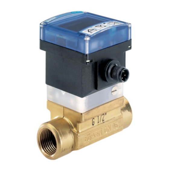
BESCHREIBUNG Durchfluss-Kontroller 8039 2.1 Aufbau/Funktion Der Durchfluss-Kontroller 8039 besteht aus einem Elektronikmodul SE39 und einem Fitting S039 mit integiertem Flügelrad. Er wurde dafür ausgelegt, ein Magnetventil zu schalten, ein Alarm auszulösen oder eine SE39 Regelschleife zu errichten. Die Frequenz-Ausgang-Ausführung des Kontrollers erlaubt es ausserdem, die Umdrehungsfrequenz des Flügelrads (2 Pulse pro Umdrehung) direkt...
Relais Stecker EN 175301-803 und M12 440382 12-30 VDC Relais und Frequenz Stecker EN 175301-803 und M12 447806 2.4 Bestell-Tabelle von Zubehör Zubehör Bestell-Nr. M12-Kupplung, 5 Pins, zum kabeln 917116 M12-Stecker, 5 Pins, am Kabel angespritzt (2 m) 438680 8039...
TECHNISCHE DATEN Durchfluss-Kontroller 8039 Allgemeine Daten Rohrleitungsdurchmesser DN6 (1/4‘’) bis DN50 (2‘‘); Verwenden Sie die Durchfluss-Geschwindigkeits-Diagramme im Anhang, um den geeigneten Rohrleitungsdurchmesser auszuwählen. Flüssigkeits-Temperatur 100 °C Flüssigkeits-Druck von der Flüssigkeitstemperatur abhängig (siehe Bedienungsanleitung des Fittings) Flüssigkeits-Viskosität max. 300 cSt Feststoffanteil max.
Polyester und Polycarbonat Fitting S039 Messing Flügelrad des Fittings S039 PVDF Achse und Lager des Fittings Keramik O-Ringe FPM standard (EPDM auf Anfrage) Umgebungs-Bedingungen Umgebungstemperatur 0 bis +60° C (+32° F bis +140° F) Relative Feuchte < 80%, nicht kondensiert 8039...
Seite 78
TECHNISCHE DATEN Durchfluss-Kontroller 8039 Messgenauigkeit mit und ohne Teach-in max. Fehl-% Mit Teach-in Ohne Teach-in, mit K-Faktor Flüssigkeits- geschwindigkeit in m/s v.E = vom Endwert v.M. = vom Messwert Diese Werte wurden unter folgenden Referenzbedingungen festgelegt: Flüssigkeit = Wasser, Wasser- und Umgebungstemperatur von 20 °C, Berücksichtigung der Mindestein- und...
Seite 79
Abmessungen (mm) EN 175301-803-Stecker 13.5 67.5 8039...
Der Durchfluss-Kontroller 8039 enthält ein Fitting S039 für den Einbau in die Rohrleitung. S039 Beim Einbau des Fittings müssen die Einbauvorschriften beachtet wer- den, die dem Fitting beiliegen. Der Kontroller 8039 so in die Rohrleitung einbauen, dass der auf dem Gehäuse aufgeklebte Pfeil die Richtung der Flüssigkeitsströmung anzeigt.
- Zum Öffnen des Steckers Ringmutter [1] vollständig - Die Dichtung [4] zwischen dem Stecker und dem lösen Steckverbinder des Kontrollers 8039 einsetzen. - Steckerhinterteil [2] abnehmen. - Den Stecker an den Kontroller 8039 anschliessen. - Gemäss Anschlussbelegung beschalten (Siehe 4.3.2) - Die Schraube [1] festschrauben. 8039...
INSTALLATION Durchfluss-Kontroller 8039 4.3.2 NPN-Transistor-Ausführung mit EN 175301-803-Stecker Sensor Empfänger (12-30 VDC) Last NPN- Ausgang NPN-Transistor-Ausgang 0 VDC NPN -Anschluss des EN 175301-803-Steckers NPN-Ausgang 4.3.3 PNP-Transistor-Ausführung mit EN 175301-803-Stecker Sensor Empfänger PNP- (12-30 VDC) Ausgang Last PNP-Transistor-Ausgang 0 VDC PNP-Ausgang...
(*) Funktionnelle Erde Sicherer Betrieb Wenn die an den Relaiskontakten anliegende Spannung höher als 24 V ist, besteht Gefahr für Menschen durch einen Stromschlag, wenn die Steckverbindung nicht korrekt eingesteckt und verschraubt wurde. Zum sicheren Betrieb alle Steckverbinder daraufhin überprüfen. 8039...
BEDIENUNG Durchfluss-Kontroller 8039 5.1 Allgemeine Hinweise Beachten Sie, dass alle Einstellungen der Parameter Auswirkungen auf den ordnungsgemässen Prozessverlauf haben können. Dokumentieren Sie die eingestellten Parameter (Tabelle S. 24). Der Frequenzausgang ist nicht programmierbar. 5.2 Funktionsübersicht Die Bedienung gliedert sich in drei Ebenen: Normalmodus Hier werden den Durchfluss und die Schaltschwellen angezeigt.
Zahlenwert (0…9) je Stelle verändern, Eingaben und Menüpunkte bestätigen Menü durchlaufen. Stelle auswählen, Menü durchlaufen 5.4 Grundeinstellung Mit dem Einschalten erhalten Sie folgende Grundeinstellung der Parameter: Durchfluss-Einheit: K-Faktor: Ausgang: Hysterese, invertiert OLO: OHI: DEL: Filter: BGLO: BGHI: EXT: No (unbenutzte Funktion) 8039...
BEDIENUNG Durchfluss-Kontroller 8039 5.5 Normalmodus Gleichzeitig auf die Anzeige des aktuell Tasten drücken gemessenen Durchflusses. ENTER > 5 s ENTER 0..9 > 5 s Zugriff zu voriger Funktion. ENTER 0..9 > 5 s 0..9 Anzeige oberer Schaltpunkt (O HI). Zugriff zu nächster Funktion.
5.6 Schaltmodi des Kontrollers 8039 Hysterese Modus Durchfluss Die Statusänderung erfolgt bei Erkennung einer Schwelle. (Zunehmender Durchfluss: hohe Schwelle (OHI) zu erkennen, abnehmender Durchfluss: niedrige Schwelle (OLO) zu erkennen). Kontakt Kontakt Nicht umgekehrt Umgekehrt Zeit Hysterese Modus Durchfluss Durchfluss OLO OHI...
Seite 90
Flüssigkeits-Durchfluss. ENTER ENTER ENTER ENTER ENTER ENTER 0..9 ** Um den «Teach-In» durchzuführen, benutzen Sie einen an ein Ventil angeschlossenen Kontroller 8039; Das Ventil dient 0..9 ENTER ENTER 0..9 0..9 0..9 dazu, einen von z.B. 200-Liter-Behälter zu füllen. Sobald «YES TEAC» angezeigt wird, drücken Sie «ENTER» und öffnen Sie das Ventil: Die Anzeige «TEAC» blinkt.
Seite 91
0..9 Glättungseffekt auf den angezeigten Durchfluss. ENTER ENTER Bestimmung der Mindest- (BG LO) und Höchst-Werte (BG HI) des Bargraphs. EXT: unbenutzte Funktion. * Der Komma wird durch Drücken der Zurück zur Anzeige des ENTER Tasten verschoben. Durchflusses im Normalmodus. 8039...
Seite 92
BEDIENUNG Durchfluss-Kontroller 8039 Ihre Einstellungen des 8039: Tragen Sie die im Kalibriermodus programmierten Werte ein. Einheit K-Faktor Modus Schewellen Umgekehrt Verz. Filter Bargraph Datum Unterschrift UNIT K FAC HYST. * FEN.** O LO O HI DEL (s) FILT BG LO BG HI...
Zugriff zu nächster Funktion. 2.500 Test der Schaltschwellen ENTER ENTER nach Eingabe eines beliebigen Durchflusswertes (SIM) und DRUCK AUF DIE ENTER-TASTE. 0..9 Zurück zur Anzeige des Durchflusses im Normalmodus. * Der Komma wird durch Drücken der Tasten verschoben. ENTER 0..9 8039...
BETRIEB Durchfluss-Kontroller 8039 6.1 Reinigung Zur Reinugen des Gerätes verwendet man Wasser oder eine für die Materialien der Fittings geeigneten Lösungsmittel. Für weitere Auskünfte, steht Ihnen Bürkert zur Verfügung. 6.2 Fehleranzeige Anzeige Beschreibung Fehlerbehebung ERR 0 Die Kalibrierdaten sind verloren gegangen.
6.3 Fehlersuche Wenn die Anzeige stets 0000 anzeigt, - überprüfen Sie, dass der Kontroller 8039 so in die Rohrleitung eingebaut ist, dass der auf dem Gehäuse des Kontrollers aufgeklebte Pfeil die Richtung der Flüssigkeitsströmung anzeigt. - überprüfen Sie, dass der programmierte K-Faktor-Wert nicht 0 gleicht (Menü...
ANHANG Durchfluss-Kontroller 8039 7.1 Anschluss-Beispiele mit dem Kontroller 8039 8039 NPN-Anschluss : Kontroller 8039 (NPN/PNP-Ausf.) und eine SPS. 24 V= PNP-Anschluss : 8039 Kontroller 8039 (NPN/PNP-Ausf.) Control und ein Top Control 8631 8631. 24 V=...
Seite 97
NPN-Anschluss : 8039 Kontroller 8039 (NPN/PNP-Ausf.) und ein Magnetventil 6014. Magnetventil Schutz- 24V, 700mA schaltkreis * * Überspannungsschutz muss 24 V= vom Anwender, abhängig von der gewählten Last, installiert werden. z.B. Steckverbindung EN 175301-803 mit PNP-Anschluss : eingebautem Varistor. 8039 Kontroller 8039 (NPN/PNP-Ausf.)
Seite 98
ANHANG Durchfluss-Kontroller 8039 8039 Stromlos geöffneter Anschluss: Magnetventil (oder Alarm) Kontroller 8039 250 VAC, (Relais-Ausführung) max. 3 A Schutz- und ein schaltkreis * Magnetventil. 24 V= 250 VAC 8039 Magnetventil (oder Alarm) 250 VAC, max. 3 A Schutz- Stromlos schaltkreis *...