Inhaltsverzeichnis
Werbung
Verfügbare Sprachen
Verfügbare Sprachen
Quicklinks
Werbung
Kapitel
Inhaltsverzeichnis

Verwandte Anleitungen für Lenze c750


Inhaltszusammenfassung für Lenze c750
- Seite 1 Montageanleitung | Mounting Instructions Controller c750 Controller c750...
-
Seite 3: Inhaltsverzeichnis
Inhalt Inhalt Über dieses Dokument Weiterführende Dokumente Sicherheitshinweise Grundlegende Sicherheitshinweise Bestimmungsgemäße Verwendung Handhabung Restgefahren Produktinformation Ausstattung Lizenzinformation Mechanische Installation Abmessungen Controller montieren I/O-System 1000 montieren Elektrische Installation Netzanschluss Netzwerke Diagnose und Störungsbeseitigung LED-Statusanzeigen Technische Daten Normen und Einsatzbedingungen Konformitäten/Approbationen Personenschutz und Geräteschutz Angaben zur EMV Umweltbedingungen Bemessungsdaten... -
Seite 4: Über Dieses Dokument
Diese Anleitung ist gültig für den Controller c750. WARNUNG! Lesen Sie diese Dokumentation sorgfältig, bevor Sie mit den Arbeiten beginnen. ▶ Beachten Sie die Sicherheitshinweise! Weiterführende Dokumente Informationen und Hilfsmittel rund um die Lenze-Produkte finden Sie im Internet: www.Lenze.com à Downloads... -
Seite 5: Sicherheitshinweise
Sicherheitshinweise Bestimmungsgemäße Verwendung Sicherheitshinweise Wenn Sie die folgenden grundlegenden Sicherheitsmaßnahmen und Sicherheitshinweise missachten, kann dies zu schweren Personenschäden und Sachschäden führen! Beachten Sie die Vorgaben der beiliegenden und zugehörigen Dokumentation. Dies ist Voraussetzung für einen sicheren und störungsfreien Betrieb, sowie für das Erreichen der angegebenen Produkteigenschaften. Beachten Sie die spezifischen Sicherheitshinweise in den anderen Abschnitten! Grundlegende Sicherheitshinweise Personal... -
Seite 6: Handhabung
Sicherheitshinweise Handhabung Handhabung • Das Produkt niemals trotz erkennbarer Schäden in Betrieb nehmen. • Das Produkt niemals technisch verändern. • Das Produkt niemals unvollständig montiert in Betrieb nehmen. • Das Produkt niemals ohne erforderliche Abdeckungen betreiben. • Alle elektrischen Verbindungen nur im spannungslosen Zustand herstellen, trennen und verändern! WARNUNG! Field Wiring Markings Wiring terminal: Voltage supply [24 V DC ±... -
Seite 7: Restgefahren
Sicherheitshinweise Restgefahren Restgefahren Produkt Beachten Sie die Warnschilder auf dem Produkt und deren Bedeutung! Elektrostatisch gefährdete Bauelemente: Vor Arbeiten am Produkt von elektrostatischer Aufladung befreien! Gefährliche elektrische Spannung: Vor Arbeiten am Produkt überprüfen, ob alle Leistungsanschlüsse spannungslos sind! Die Leistungsanschlüsse führen nach Netzausschalten für die bei dem Symbol angegebene Zeit gefährliche elektrische Spannung! Hoher Ableitstrom: Festinstallation und PE−Anschluss nach Norm ausführen:... - Seite 8 Sicherheitshinweise Restgefahren HINWEIS Hohe Eingangsspannung am Gerät. Zerstörung des Geräts. ▶ Maximal zulässige Eingangsspannung beachten. ▶ Gerät am Eingang gegen zu hohe Eingangsspannung absichern. HINWEIS Kurzschluss am Gerät durch elektrostatische Entladung. Zerstörung des Geräts. ▶ Das Personal muss sich von elektrostatischer Ladung befreien, bevor es am Gerät arbeitet. HINWEIS Freiräume am Rückwandbus.
-
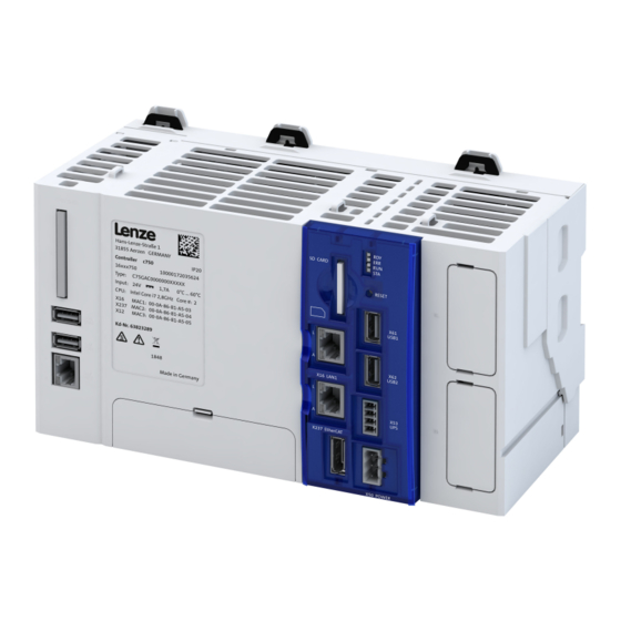
Seite 9: Produktinformation
DisplayPort 1.2 Lizenzinformation Lenze Software kann Software−Bestandteile enthalten, die als Freie Software oder als Open Source lizenziert sind. Die Lizenzbedingungen der in diesem Produkt verwendeten Open Source Software −Komponenten stehen Ihnen auf der im Produkt enthaltenen SD−Karte im Verzeichnis "Licenses" zur... -
Seite 10: Mechanische Installation
Mechanische Installation Controller montieren Mechanische Installation Abmessungen Höhe Breite Tiefe Gewicht 114.5 1.64 Controller montieren Montagebedingungen • Einbauort: Im Schaltschrank (Indoor use) • Einbaulage: Horizontal • Einbauart: Montage auf Hutschiene • Einbaufreiraum: oben 50 mm, unten 50 mm Montage und Demontage des Controllers... -
Seite 11: I/O-System 1000 Montieren
Mechanische Installation I/O-System 1000 montieren I/O-System 1000 montieren Montage und Demontage des I/O-Systems 1000 und der Abdeckkappe... -
Seite 12: Elektrische Installation
Elektrische Installation Elektrische Installation Netzanschluss Wird der PE-Leiter nicht mit der Versorgung zugeführt, muss das PE-Potential an einem Erdungs- punkt in der Nähe des Einbauortes aufgelegt werden. Die maximal zulässige Eingangsspannung beachten. Das Gerät eingangsseitig fachgerecht gegen Spannungsschwankungen und Spannungsspitzen absichern. Beachten Sie: Der Controller startet, sobald die Versorgungsspannung anliegt. - Seite 13 Netzanschluss Anschluss an eine externe USV Für die Verwendung des Controllers c750 mit Windows 10 IoT ist eine externe unterbrechungsfreie Strom- versorgung (USV) vorzusehen, die bei Ausfall der 24-V-Versorgung Windows genügend Zeit bereitstellt, um sich geordnet beenden zu können. Die externe USV puffert dabei die 24-V-Versorgung am Stecker X50 des Gerätes.
-
Seite 14: Netzwerke
Elektrische Installation Netzwerke Netzwerke X61/X62: Die Länge des USB-Kabels darf 3 m nicht überschreiten. X63/X64: Die Länge des USB-Kabels darf 5 m nicht überschreiten. Zugspannung und Vibrationen führen zu einer instabilen Netzwerkverbindung. Verlegen Sie die Netzwerkkabel halbkreisförmig und fixieren Sie die Netzwerkkabel an den Verzurrösen. Abb. -
Seite 15: Diagnose Und Störungsbeseitigung
Diagnose und Störungsbeseitigung LED-Statusanzeigen Diagnose und Störungsbeseitigung LED-Statusanzeigen Die Controller verfügen über LEDs, die den aktuellen Betriebszustand signalisieren. Abhängig von der jeweils laufenden Software-Applikation sind unterschiedliche Ansteuerungen der LEDs möglich. LED-Statusanzeige LED "RDY" (blau/gelb) Bedeutung Gerät ist ausgeschaltet. Gerät startet. Gerät ist betriebsbereit. -
Seite 16: Technische Daten
Technische Daten Angaben zur EMV Technische Daten Normen und Einsatzbedingungen Konformitäten/Approbationen Konformität und Approbation 2014/30/EU EMV-Richtlinie Angewandte harmonisierte Normen: EN 61000-6-2:2005 + AC:2005 EN 61000-6-4:2007 + A1:2011 EN 55024:2010 RoHS 2011/65/EU RoHS-Richtlinie Angewandte harmonisierte Normen: EN 50581:2012 Personenschutz und Geräteschutz Personenschutz und Geräteschutz Schutzart EN 60529... -
Seite 17: Umweltbedingungen
Betrieb EN 60721-3-2 3K3: c520: 0°C bis 60°C für horizontalen Einbau c550/c750 (mit Lüfter): 0°C bis 60°C für horizontalen Einbau Hinweis: Die Pufferzeit der RTC ist für vier Wochen ausgelegt. In Abhän- gigkeit der Umgebungstemperatur ergibt sich ein Derating der Pufferzeit. - Seite 18 Technische Daten Bemessungsdaten...
- Seite 19 Contents Contents About this document Further documents Safety instructions Basic safety instructions Application as directed Handling Residual hazards Product information Features Licence information Mechanical installation Dimensions Mounting the controller Mounting the I/O system 1000 Electrical installation Mains connection Networks Diagnostics and fault elimination LED status display Technical data Standards and operating conditions...
-
Seite 20: About This Document Further Documents
These instructions apply to the c750 controller. WARNING! Read this documentation carefully before starting any work. ▶ Please observe the safety instructions! Further documents Information and tools with regard to the Lenze products can be found on the Internet: www.Lenze.com à Downloads... -
Seite 21: Safety Instructions
Safety instructions Application as directed Safety instructions Disregarding the following basic safety measures and safety information may lead to severe personal injury and damage to property! Observe all specifications of the corresponding documentation supplied. This is the precondition for safe and trouble-free operation and for obtaining the product features specified. -
Seite 22: Handling
Safety instructions Handling Handling • Never commission the product in the event of visible damage. • The product must never be technically modified. • Never commission the product before assembly has been completed. • The product must never be operated without required covers. •... -
Seite 23: Residual Hazards
Safety instructions Residual hazards Residual hazards Product Observe the warning labels on the product! Electrostatic sensitive devices: Before working on the product, the staff must ensure to be free of electrostatic charge! Dangerous electrical voltage: Before working on the product, make sure there is no voltage applied to the power terminals! After mains disconnection, the power terminals will still carry the hazardous electrical voltage for the time given next to the symbol! High leakage current:... - Seite 24 Safety instructions Residual hazards NOTICE High input voltage at the device. Destruction of the device. ▶ Observe maximum permissible input voltage. ▶ Fuse device at the input against too high input voltage. NOTICE Short circuit at the device due to electrostatic discharge. Destruction of the device.
-
Seite 25: Product Information
DisplayPort 1.2 Licence information Lenze Software may contain software elements that are licensed as free software or open source. The licensing terms and conditions of the open source software components used in this product can be found in the "License" directory on the SD card included in the product. -
Seite 26: Mechanical Installation
Mechanical installation Mounting the controller Mechanical installation Dimensions Height Width Depth Weight 114.5 1.64 Mounting the controller Mounting conditions • Mounting place: In the control cabinet (indoor use) • Mounting position: Horizontal • Mounting type: DIN rail mounting • Mounting clearance: above 50 mm, below 50 mm Mounting and dismounting the controller... -
Seite 27: Mounting The I/O System 1000
Mechanical installation Mounting the I/O system 1000 Mounting the I/O system 1000 Mounting and dismounting the I/O system 1000 and the cover... -
Seite 28: Electrical Installation
Electrical installation Electrical installation Mains connection If the PE conductor is not part of the supply, the PE potential must be applied at an earthing point near the site of installation. Observe the maximum permissible input voltage. Fuse the device professionally against voltage fluctuations and voltage peaks at the input side. - Seite 29 Connection to an external UPS For the use of the c750 controller with Windows 10 IoT, an external uninterruptible power supply (UPS) must be provided which, in the event of a 24 V power supply failure, allows Windows sufficient time to be ended in an orderly manner.
-
Seite 30: Networks
Electrical installation Networks Networks X61/X62: The USB cable must not exceed a length of 3 m. X63/X64: The USB cable must not exceed a length of 5 m. Tensile stress and vibrations cause an unstable network connection. Lay network cables in semicircular fashion and fix the cables on the lashing eyes. -
Seite 31: Diagnostics And Fault Elimination
Diagnostics and fault elimination LED status display Diagnostics and fault elimination LED status display The controllers are equipped with LEDs indicating the current operating status. Depending on the running software application, different control modes of the LEDs are possible. LED status display "RDY"... -
Seite 32: Technical Data
Technical data EMC data Technical data Standards and operating conditions Conformities/approvals Conformity and approval 2014/30/EU EMC Directive Applied harmonised standards: EN 61000-6-2:2005 + AC:2005 EN 61000-6-4:2007 + A1:2011 EN 55024:2010 RoHS 2011/65/EU RoHS Directive Applied harmonised standards: EN 50581:2012 Protection of persons and device protection Protection of persons and device protection Degree of protection EN 60529... -
Seite 33: Environmental Conditions
EN 60721-3-2 3K3: c520: 0°C to 60°C for horizontal installation c550/c750 (with fan): 0°C to 60°C for horizontal installation Note: The buffer time of the RTC is designed for four weeks. Depending on the ambient temperature, the buffer time may be derated. - Seite 34 © 10/2019 | 13584917 | 1.0 Lenze Automation GmbH Postfach 101352, 31763 Hameln Hans-Lenze-Str. 1, 31855 Aerzen GERMANY HR Hannover B 205381 Phone +49 5154 82-0 Fax +49 5154 82-2800 sales.de@lenze.com www.Lenze.com Lenze Service GmbH Breslauer Straße 3, D-32699 Extertal...