Herunterladen Inhalt Inhalt Diese Seite drucken

Werbung

Verfügbare Sprachen
  • DE

Verfügbare Sprachen

  • DEUTSCH, seite 1
Maverick
Dunstabzugshaube
Range Hood
Campana extractora
Hotte aspirante
Cappa aspirante
10033716

Werbung

Inhaltsverzeichnis
loading

Inhaltszusammenfassung für Klarstein Maverick

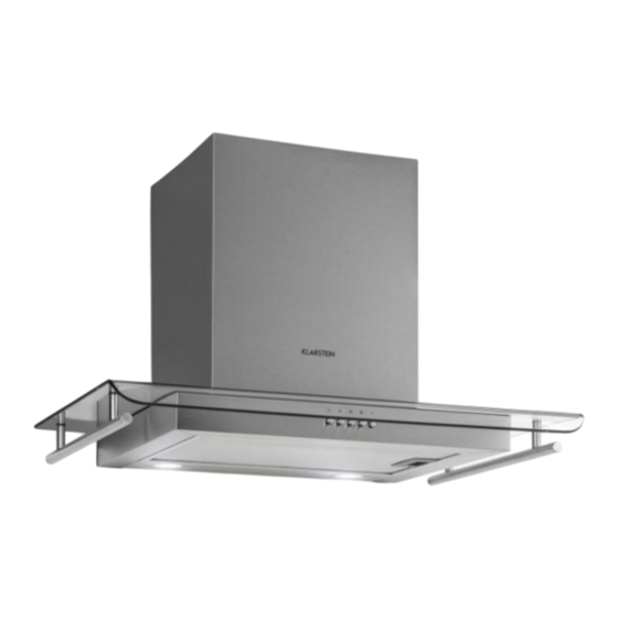
  • Seite 1 Maverick Dunstabzugshaube Range Hood Campana extractora Hotte aspirante Cappa aspirante 10033716...
  • Seite 3: Inhaltsverzeichnis

    Sehr geehrter Kunde, wir gratulieren Ihnen zum Erwerb Ihres Gerätes. Lesen Sie die folgenden Hinweise sorgfältig durch und befolgen Sie diese, um möglichen Schäden vorzubeugen. Für Schäden, die durch Missachtung der Hinweise und unsachgemäßen Gebrauch entstehen, übernehmen wir keine Haftung. Scannen Sie den folgenden QR-Code, um Zugriff auf die aktuellste Bedienungsanleitung und weitere Informationen rund um das Produkt zu erhalten:...
  • Seite 4: Sicherheitshinweise

    SICHERHEITSHINWEISE • Lesen Sie sich alle Hinweise vor der Benutzung sorgfältig durch und bewahren Sie die Bedienungsanleitung zum späteren Nachschlagen gut auf. • Die Montagearbeiten dürfen nur von einem Elektrofachmann oder einer Fachkraft durchgeführt werden. Bevor Sie die Dunstabzugshaube verwenden, stellen Sie sicher, dass die Spannung (V) und die auf der Dunstabzugshaube angegebene Frequenz (Hz) der Spannung (V) und Frequenz (Hz) ihrer Stromversorgung entsprechen.
  • Seite 5 Wichtige Hinweise zum Abluftbetrieb WARNUNG Vergiftungsgefahr durch zurückgesaugte Abgase! Betreiben Sie das Gerät nicht im Abluftbetrieb, wenn es zusammen mit einer raumluftabhängigen Feuerstätte betrieben wird und keine ausreichende Luftzirkulation garantiert wird. Raumluftabhängige Feuerstätten, wie Gas-, Öl-, Holz- oder Kohleheizungen, Boiler oder Durchlauferhitzer) beziehen die Luft aus dem Raum und führen Sie durch ein Abluftrohr oder eine Kamin ins Freie.
  • Seite 6: Geräteübersicht

    GERÄTEÜBERSICHT Stk. Gerätekomponenten Gerätekorpus, inklusive: Bedienelementen, Licht, Gebläse, Filter Untere Abdeckung (optional) Obere Abdeckung (optional) Bund (optional) Abluftrohr Aktivkohlefilter (optional) Hinweis: Das optionale Zubehör ist nicht im Lieferumfang enthalten.
  • Seite 7: Installationszubehör

    INSTALLATIONSZUBEHÖR Stk. Teil Schrauben 5x50 Dübel Schrauben 4,2x9,5 Schrauben M4x20 Unterlegscheiben Abstandhalter Befestigungswinkel Abzugshaube Abdeckungswinkel (optional) Griff...
  • Seite 8: Abmessungen Und Abstände

    ABMESSUNGEN UND ABSTÄNDE Hinweis: Bei den angegebenen Werten handelt es sich um [mm].
  • Seite 9 Hinweis: Bei den angegebenen Werten handelt es sich um [mm].
  • Seite 10: Installation

    INSTALLATION Hinweis: Bei den angegebenen Werten handelt es sich um [mm]. Referenzlinie...
  • Seite 11 Markierungslinien Ziehen Sie als ersten Schritt zunächst folgende Linien: • Eine senkrechte Referenzlinie zur Decke oder zu der oberen Begrenzung, im Zentrum der Stelle, an der die Dunstabzugshaube angebracht werden soll. (A) Eine horizontale Linie A, 1083–1 183 mm oberhalb der Kochfläche. (B) Eine horizontale Linie B, 40-377 mm über der horizontalen Linie A.
  • Seite 12 Einhaken des Gerätekorpus • Haken Sie den Gerätekorpus an dem Befestigungswinkel ein. • Richten Sie den Gerätekorpus aus. • Befestigen Sie das Abluftrohr am Haubenkörper. • Verbinden Sie die Schornsteinhalterung (21) und den unteren dekorativen Schornstein (2.1). • Befestigen Sie die Schornsteinhalterung (21) mit 2 Schrauben ST 5*50 an der horizontalen Linie A, um ein versehentliches Abrutschen des Haubenkörpers von der Schornsteinhalterung zu verhindern.
  • Seite 13: Anbringen Des Dunstabzugs

    ANBRINGEN DES DUNSTABZUGS Der Dunstabzug kann nur in Kombination mit einer Dunstabzugshaube angebracht werden. Untere Abdeckung Befestigen Sie den unteren dekorativen Schornstein mit 2 Schrauben (4,2*9,5), die mit der Haube mitgeliefert werden, an der Schornsteinhalterung. Obere Abdeckung Setzen Sie die obere Abdeckung in die untere Abdeckung ein und fixieren Sie die obere Abdeckung mit 2 Schrauben (4,2x9,5) am Befestigungswinkel.
  • Seite 14: Tastenfunktionen

    TASTENFUNKTIONEN Motor ein/aus Niedrige Geschwindigkeit Mittlere Geschwindigkeit Hohe Geschwindigkeit Licht ein/aus...
  • Seite 15: Reinigung Und Pflege

    REINIGUNG UND PFLEGE Reinigung der Fettfilter • Die Filter müssen, abhängig von der Verwendungshäufigkeit, mindestens alle 2 Monate gereinigt werden. Die Filter sind spülmaschinengeeignet. • Entnehmen Sie die Filter, indem Sie diese gegen die Rückseite der Dunstabzugshaube drücken und gleichzeitig nach unten ziehen. •...
  • Seite 16 Aktivkohlefilter (Umluftversion) Diese Filter können nicht abgewaschen und wiederverwendet werden. Aktivkohlefilter müssen, je nach Verwendungshäufigkeit, mindestens alle 4 Monate gewechselt werden. Austausch der Aktivkohlefilter: Befestigen: Entfernen: 1. Einsetzen 1. Nach vorne 2. Nach vorne drückern ziehen 2. Abnehmen Entfernen: 1. Nach vorne Befestigen: ziehen 1.
  • Seite 17: Fehlerbehebung

    Ersatzlicht ILCOS D Ø Leistung Spannung Bild code DSR- 70 mm 1,5 W DC 12 V 1.5-S-70 FEHLERBEHEBUNG Problem Ursache Lösung Das Licht ist an, aber der Die Flügelblätter sind Überprüfen Sie die Motor läuft nicht. blockiert. Flügelblätter. Der Kondensator ist Ersetzen Sie den beschädigt.
  • Seite 18: Hinweise Zur Entsorgung

    Problem Ursache Lösung Unzureichende Die Entfernung zwischen Passen Sie den Abstand Luftabsaugung Kochfläche und Dunstabzugshaube ist zu groß. Zu viel Luftzug durch Wählen Sie einen neuen geöffnete Türen oder Installationsort oder Fenster. schließen Sie Türen/ Fenster. Das Gerät neigt sich nach Die Fixierschrauben Ziehen Sie die Schrauben vorne...
  • Seite 19 Dear Customer, Congratulations on purchasing this equipment. Please read this manual carefully and take care of the following hints to avoid damages. Any failure caused by ignoring the items and cautions mentioned in the instruction manual is not covered by our warranty and any liability. Scan the QR code to get access to the latest user mannual and other information about the product CONTENT...
  • Seite 20: Safety Instructions

    SAFETY INSTRUCTIONS • Thank you for purchasing this cooker hood. Please read the instruction manual carefully before you use the cooker hood, and keep it in a safe place. • The installation work must be carried out by a qualified electrician or competent person.
  • Seite 21 Important notes about the extraction mode WARNING Risk of poisoning from exhaust gases sucked back. Never operate the device in extraction mode simultaneously with an open flue appliance when there is not adequate airflow guaranteed. Open fl ue combustion equipment (for example, gas, oil, wood or coal-fi red heaters, tankless water heaters, water heaters) pulls combustion air from the room and runs it through an exhaust pipe or chimney to the outside.
  • Seite 22: Product Overview

    PRODUCT OVERVIEW Ref. Qty. Product Components Hood Body, complete with: Controls, Light, Blower, Filter. Lower Decorative Chimney (optional) Upper Decorative Chimney (optional) Flange (optional) Exhaust Pipe The Activated Charcoal filter (optional) Note: The optional accessory is not included in the delivery.
  • Seite 23: Installation Components

    INSTALLATION COMPONENTS Ref. Qty. Component Screws 5x50 Wall Plugs Screws 4,2x9,5 Screws M4x20 Washers Spare Hood fixing bracket Chimney fixing bracket (optional) Handle...
  • Seite 24: Dimensions

    DIMENSIONS Note: The specified values are [mm].
  • Seite 25 Note: The specified values are [mm].
  • Seite 26: Installation

    INSTALLATION Note: The specified values are [mm]. Vertical line...
  • Seite 27 Wall Drilling and Bracket Fixing As a first step, proceed with the following drawings: • A vertical line up to the ceiling or up to the upper limit, at the center of the area in which the hood is to be fitted. (A) A horizontal line A at 1083–1 183 mm above the cooker top.
  • Seite 28 Hook the hood body • Hook the hood body to the bracket. • Level the hood body itself. • Attach the exhaust pipe to the hood body. • Connect the chimney bracket (21) to the lower decorative chimney (2.1). • Attach the chimney bracket (21) to horizontal line A with 2 ST 5*50 screws to prevent the hood body from accidentally slipping off the chimney mount.
  • Seite 29: Chimney Assembly

    CHIMNEY ASSEMBLY The chimney can only be installed with exhausting hood. Lower Decorative Chimney Fix the Lower Decorative Chimney to Chimney fixing bracket with 2 screws (4.2*9.5) supplied with the hood. Upper Decorative Chimney Insert the upper decorative chimney into the lower decorative chimney and fix the upper chimney onto the bracket with 2 screws (4.2x9.5) supplied with the hood.
  • Seite 30: Key Functions

    KEY FUNCTIONS Motor on/off Low speed Average speed High speed Light on/off...
  • Seite 31: Care And Cleaning

    CARE AND CLEANING Grease Filters • The filters must be cleaned every 2 months of operation, or more frequently for particularly heavy usage, and can be washed in a dishwasher. • Remove the filters one by one pushing them towards the back side of the hood unit and simultaneously pulling downwards.
  • Seite 32 Activated carbon filter (circulating air version) These filters cannot be washed off and reused. Depending on the frequency of use, activated carbon filters must be replaced at least every 4 months. Replacing the activated carbon filters: Fix: Remove: 1. Put in 1.
  • Seite 33: Troubleshooting

    Replacement Light ILCOS D Ø Max Power Voltage Picture code DSR- 70 mm 1,5 W DC 12 V 1.5-S-70 TROUBLESHOOTING Problem Cause Solution Light on, but motor does The blades are blocked. Check the blades. not work The capacitor is damaged. Replace capacitor.
  • Seite 34: Hints On Disposal

    Problem Cause Solution Insufficient suction The distance between Readjust the distance. the cooker hood and the cooker top is too large. Too much ventilation from Choose a new place open doors or windows. to install the appliance or close some doors / windows.
  • Seite 35 Estimado cliente: Le felicitamos por la adquisición de este producto. Lea atentamente el siguiente manual y siga cuidadosamente las instrucciones de uso con el fin de evitar posibles daños. La empresa no se responsabiliza de los daños ocasionados por un uso indebido del producto o por haber desatendido las indicaciones de seguridad.
  • Seite 36: Indicaciones De Seguridad

    INDICACIONES DE SEGURIDAD • Lea atentamente todas las indicaciones y conserve este manual para consultas posteriores. • Los trabajos de montaje deben ser realizados solamente por un electricista u otro profesional. Antes de utilizar la campana extractora, asegúrese de que la tensión (V) y la frecuencia indicada en la campana extractora (Hz) coinciden con la tensión (V) y frecuencia (Hz) de su suministro eléctrico.
  • Seite 37 Notas importantes acerca del modo de extracción ADVERTENCIA Peligro de muerte, riesgo de intoxicación provocado por gases en combustión aspirados. Nunca ponga en funcionamiento la función de acción simultáneamente con un dispositivo que genere calor en una estancia estanca si no se ha garantizado una ventilación sufi ciente. Los dispositivos no estancos que generan calor (por ejemplo, radiadores que funcionan con gas, aceite, madera o carbón, calentadores, calentadores de agua) extraen el aire de combustión de la estancia correspondiente y canalizan el aire de salida por medio...
  • Seite 38: Descripción Del Aparato

    DESCRIPCIÓN DEL APARATO Núm. Uds. Componentes del aparato Base del aparato, que incluye: Elementos de control, luz, ventilador, filtro Cubierta inferior (opcional) Cubierta superior (opcional) Unión (opcional) Conducto de extracción Filtro de carbón activo (opcional) Advertencia: Los accesorios opcionales no están incluidos en el envío.
  • Seite 39: Accesorios De Instalación

    ACCESORIOS DE INSTALACIÓN Núm. Uds. Pieza Tornillos 5 x 50 Tacos Tornillos 4,2 x 9,5 Tornillos M4 x 20 Arandela Separador Soporte de fijación de la campana Soporte para la cubierta (opcional) Mango...
  • Seite 40: Dimensiones Y Distancias

    DIMENSIONES Y DISTANCIAS Advertencia: Las medidas indicadas se expresan en „mm“.
  • Seite 41 Advertencia: Las medidas indicadas se expresan en „mm“.
  • Seite 42: Instalación

    INSTALACIÓN Advertencia: Las medidas indicadas se expresan en „mm“. Línea de referencia...
  • Seite 43 Línea de marca Como primer paso, marque las siguientes líneas: • Una línea de referencia vertical al techo o al límite superior en el centro del punto donde va a instalar la campana. (A) Una línea horizontal A, a 1083–1 183 mm por encima de la superficie de cocción. (B) Una línea horizontal B, a 40-377 mm sobre la línea horizontal A.
  • Seite 44 Colgar la estructura • Cuelgue el cuerpo del aparato en los soportes de sujeción. • Oriente bien la estructura. • Conecte el tubo de escape al cuerpo de la campana. • Conecte el soporte de la chimenea (21) a la chimenea decorativa inferior (2.1). •...
  • Seite 45: Montaje Del Tiro De Extracción

    MONTAJE DEL TIRO DE EXTRACCIÓN El tiro de extracción solo puede montarse junto con una campana extractora. Cubierta inferior Fije la chimenea decorativa inferior al soporte de fijación de la chimenea con los 2 tornillos (4.2*9.5) suministrados con la campana. Cubierta superior Coloque la cubierta superior en la cubierta inferior y fije la cubierta superior con 2 tornillos (4,2x9,5) al ángulo de fijación.
  • Seite 46: Funciones De Las Teclas

    FUNCIONES DE LAS TECLAS Motor encendido/apagado Baja velocidad Velocidad media Alta velocidad Luz encendida/apagada...
  • Seite 47: Limpieza Y Cuidado

    LIMPIEZA Y CUIDADO Limpieza del filtro antigrasa • Los filtros deben limpiarse cada dos meses, independientemente de la frecuencia de uso. Los filtros pueden lavarse en el lavavajillas. • Retire los filtros presionándolos contra la parte trasera de la campana y tirando de ellos hacia abajo.
  • Seite 48 Filtro de carbón activo (versión circulación de aire) Este filtro no puede lavarse y reutilizarse. Los filtros de carbón activo deben cambiarse al menos cada 4 meses en función de la frecuencia de uso. Sustitución del filtro de carbón activo: Fijar: Retirar: 1.
  • Seite 49: Resolución De Problemas

    Luz de repuesto Código Ø Potencia Tensión Imagen ILCOS D DSR- 70 mm 1,5 W DC 12 V 1.5-S-70 RESOLUCIÓN DE PROBLEMAS Problema Causa Solución La luz está encendida Las alas del ventilador Compruebe las aspas del pero el motor no funciona. están bloqueadas.
  • Seite 50: Retirada Del Aparato

    Problema Causa Solución Extracción de aire La distancia entre la Reduzca la distancia. insuficiente. campana y la superficie de cocción es demasiado grande. Demasiado aire en Seleccione otra ubicación movimiento por puertas o de instalación o cierre las ventanas abiertas. puertas y ventanas.
  • Seite 51 Cher client, Toutes nos félicitations pour l’acquisition de ce nouvel appareil. Veuillez lire attentivement les instructions suivantes de branchement et d’utilisation afin d’éviter d’éventuels dommages. Le fabricant ne saurait être tenu pour responsable des dommages dus au non-respect des consignes de sécurité et à la mauvaise utilisation de l’appareil.
  • Seite 52: Consignes De Sécurité

    CONSIGNES DE SÉCURITÉ • Lisez attentivement toutes les consignes avant d’utiliser l’appareil et conservez ce mode d’emploi pour vous y référer ultérieurement. • Les travaux de montage doivent être effectués uniquement par électricien professionnel ou un spécialiste. Avant d‘utiliser la hotte aspirante, assurez-vous que la tension (V) et la fréquence indiquée sur la hotte aspirante (Hz) correspondent à...
  • Seite 53 Remarques importantes concernant le mode d‘extraction AVERTISSEMENT Danger de mort, risques d‘intoxication ! Par la ré-aspiration de gaz de combustion. Ne jamais utiliser la fonction d’aspiration de l’appareil en même temps qu’un foyer dépendant de l’air ambiant si l’air frais est insuffi sant.
  • Seite 54: Aperçu De L'appareil

    APERÇU DE L‘APPAREIL N° Qté Composant de l'appareil Corps de l‘appareil, comprenant : Eléments de commande, éclairage, ventilateur, filtre Cache inférieur (en option) Cache supérieur (en option) Raccord (en option) Tuyau d'extraction Filtre à charbon actif (en option) Remarque : les accessoires en option ne sont pas inclus dans la livraison.
  • Seite 55: Matériel D'installation

    MATÉRIEL D‘INSTALLATION N° Qté Pièce Vis 5x50 Cheville Vis 4,2x9,5 Vis m4x20 Rondelle Entretoise Equerre de fixation de la hotte aspirante Equerre cache (en option) Poignée...
  • Seite 56: Dimensions Et Espacements

    DIMENSIONS ET ESPACEMENTS Remarque : les valeurs sont données en mm.
  • Seite 57 Remarque : les valeurs sont données en mm.
  • Seite 58: Installation

    INSTALLATION Remarque : les valeurs sont données en mm. Ligne de référence...
  • Seite 59 Lignes de marquage Commencez par dessiner les lignes suivantes : • Une ligne de référence verticale au plafond ou à la limite supérieure, au centre de l‘endroit où la hotte aspirante doit être installée. (A) Une ligne horizontale A, 1083–1 183 mm au-dessus de la surface de cuisson. (B) Une ligne horizontale B, 40-377 mm au-dessus de la ligne horizontale A.
  • Seite 60 Accrochage du corps de la hotte • Accrochez le corps de l‘appareil à l‘équerre de fixation. • Alignez le corps de l‘appareil. • Fixez le tuyau d‘échappement au corps du capot. • Raccordez le support de cheminée (21) à la cheminée décorative inférieure (2.1). •...
  • Seite 61: Installation De L'extraction

    INSTALLATION DE L‘EXTRACTION L‘extracteur ne peut être installé qu‘en combinaison avec une hotte aspirante. Cache inférieur Fixez la cheminée décorative inférieure au support de fixation de la cheminée avec les 2 vis (4.2*9.5) fournies avec le capot. Cache supérieur Insérez le cache supérieur dans le cache inférieur et fixez-le sur l‘équerre de fixation à...
  • Seite 62: Fonctions Des Touches

    FONCTIONS DES TOUCHES Mise en marche/arrêt du moteur Basse vitesse Vitesse moyenne Haute vitesse Allumage/extinction de la lumière...
  • Seite 63: Nettoyage Et Entretien

    NETTOYAGE ET ENTRETIEN Nettoyage du filtre à graisse • Les filtres doivent être nettoyés au moins tous les 2 mois, en fonction de la fréquence d‘utilisation. Les filtres sont compatibles lave-vaisselle. • Retirez les filtres en les appuyant contre l‘arrière de la hotte tout en tirant. •...
  • Seite 64 Filtres à charbon actif (version recirculation d‘air) Ces filtres ne peuvent pas être lavés pour être réutilisés. Les filtres à charbon actif doivent être changés au moins tous les 4 mois, en fonction de la fréquence d‘utilisation. Remplacement des filtres à charbon actif : Fixation : Démontage : 1.
  • Seite 65: Résolution Des Problèmes

    Ampoule de rechange code ILCOS Ø Puissance Tension Schéma DSR- 70 mm 1,5 W DC 12 V 1.5-S-70 RÉSOLUTION DES PROBLÈMES Problème Cause solution L'éclairage est allumé mais Une pale de ventilateur est Eliminez le blocage. le moteur ne fonctionne bloquée.
  • Seite 66: Conseils Pour Le Recyclage

    Problème Cause solution Puissance d'aspiration La distance entre la hotte Ajustez la distance. insuffisante et la surface de cuisson est trop grande. Trop de courants d'air dus Choisissez un autre lieu à des portes ou fenêtres d'installation ou fermez les ouvertes.
  • Seite 67 Gentile cliente, La ringraziamo per aver acquistato il dispositivo. La preghiamo di leggere attentamente le seguenti istruzioni per l’uso e di seguirle per evitare possibili danni tecnici. Non ci assumiamo alcuna responsabilità per danni scaturiti da una mancata osservazione delle avvertenze di sicurezza e da un uso improprio del dispositivo.
  • Seite 68: Avvertenze Di Sicurezza

    AVVERTENZE DI SICUREZZA • Leggere attentamente tutte le istruzioni prima dell´uso e conservare il manuale per consultazioni future. • Il montaggio può essere eseguito solo da un tecnico qualificato. Prima di utilizzare la cappa aspirante, accertarsi che la tensione (V) e la frequenza (Hz) indicate corrispondano alla tensione (V) e alla frequenza (Hz) domestiche.
  • Seite 69 Note importanti circa la modalità di estrazione AVVERTIMENTO Pericolo di morte, pericolo di intossicazione da gas di scarico! Non azionare l´apparecchio con funzione di scarico mentre è attivo un impianto di riscaldamento che utilizza l´aria ambiente, se l´areazione non è suffi ciente. Gli impianti di riscaldamento che sfruttano l´aria ambiente (ad es.
  • Seite 70: Descrizione Del Dispositivo

    DESCRIZIONE DEL DISPOSITIVO Numero Pezzi Componenti del dispositivo Corpo del dispositivo, inclusi: elementi di controllo, luce, ventola, filtro Copertura inferiore (opzionale) Copertura superiore (opzionale) Flangia (opzionale) Tubo di scarico dell’aria Filtro ai carboni attivi (opzionale) Avvertenza: gli accessori opzionali non sono inclusi nel volume di consegna.
  • Seite 71: Accessori Per L'installazione

    ACCESSORI PER L’INSTALLAZIONE Numero Pezzi Componenti del dispositivo Viti 5x50 Tasselli Viti 4,2x9,5 Viti M4x20 Rondelle Distanziatori Angolare di fissaggio cappa aspirante Angolare di copertura (opzionale) Maniglia...
  • Seite 72: Dimensioni E Distanze

    DIMENSIONI E DISTANZE Avvertenza: i valori indicati sono in (mm).
  • Seite 73 Avvertenza: i valori indicati sono in (mm).
  • Seite 74: Installazione

    INSTALLAZIONE Avvertenza: i valori indicati sono in (mm). inea di riferimento...
  • Seite 75 Linee di riferimento Per prima cosa, realizzare le seguenti linee: • Una linea di riferimento verticale verso il soffitto o verso la delimitazione superiore, al centro del punto in cui viene installata la cappa aspirante. (A) Una linea orizzontale A, 1083-1 183 mm sopra al piano cottura. (B) Una linea orizzontale B, 40-377 mm sopra alla linea orizzontale A.
  • Seite 76 Agganciare il corpo del dispositivo • Agganciare il corpo del dispositivo all’angolare di fissaggio. • Posizionare il corpo del dispositivo correttamente. • Collegare il tubo di scarico al corpo della cappa. • Collegare il supporto della canna fumaria (21) alla canna fumaria decorativa inferiore (2.1).
  • Seite 77: Installazione Della Canna Di Aspirazione

    INSTALLAZIONE DELLA CANNA DI ASPIRAZIONE La canna può essere montata solo in combinazione con la cappa aspirante. Copertura inferiore Fissare la canna fumaria decorativa inferiore alla staffa di fissaggio della canna fumaria con 2 viti (4,2*9,5) fornite con il cappuccio. Copertura superiore Inserire la copertura superiore in quella inferiore e fissare la copertura superiore all’angolare di fissaggio con 2 viti (4,2x9,5).
  • Seite 78: Tasti Funzione

    TASTI FUNZIONE Accensione/spegnimento del motore Bassa velocità Velocità media Alta velocità Luce acceso/spento...
  • Seite 79: Pulizia E Manutenzione

    PULIZIA E MANUTENZIONE Pulire i filtri antigrasso • In base alla frequenza di utilizzo, i filtri devono essere puliti almeno ogni 2 mesi. I filtri sono adatti a lavastoviglie. • Rimuovere tutti i filtri, premendoli contro la parete posteriore della cappa e spingendoli contemporaneamente verso il basso.
  • Seite 80 Filtro ai carboni attivi (versione di ricircolo) Questi filtri non possono essere lavati e riutilizzati. I filtri ai carboni attivi, in base alla frequenza di utilizzo, devono essere sostituiti almeno ogni 4 mesi. Sostituire il filtro ai carboni attivi: Fissare: Rimuovere: 1.
  • Seite 81: Correzione Degli Errori

    Lampadina di ricambio Codice ILCOS Ø Potenza Tensione Immagine DSR- 70 mm 1,5 W DC 12 V 1.5-S-70 CORREZIONE DEGLI ERRORI Problema Causa Soluzione La luce è accesa ma il Le pale della ventola sono Controllare le pale della motore non funziona. bloccate.
  • Seite 82: Smaltimento

    Problema Causa Soluzione Aspirazione insufficiente. La distanza tra piano Regolare la distanza. cottura e cappa è eccessiva. Corrente d’aria eccessiva Cambiare luogo dovuta a porte o finestre d’installazione o chiudere aperte. porte/finestre. Il dispositivo si inclina in Le viti di fissaggio non Stringere le viti e avanti.

Inhaltsverzeichnis