Werbung
Verfügbare Sprachen
Verfügbare Sprachen
Quicklinks
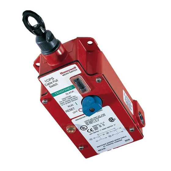
Installation Instructions for the Cable Pull Safety Switch (1CPS Series)
Instrucciones de instalación para el interruptor de seguridad de tracción de cable (Serie 1CPS)
Einbauanweisungen für Sicherheitsseilzugschalter (Serie 1CPS)
Instructions d'installation de l'interrupteur de sécurité à câble (série 1CPS)
Istruzioni di installazione per l'interruttore di sicurezza con cavo di azionamento (serie 1CPS)
WARNING
IMPROPER INSTALLATION
•
Consult with local safety agencies and their
requirements when designing a machine control link,
interface and all control elements that affect safety.
•
Strictly adhere to all installation instructions.
Failure to comply with these instructions could result
in death or serious injury.
WARNING
IMPROPER USE
•
Use the 1CPS Cable Pull Safety Switch in emergency
stop applications only. Do not use in general production
stop applications.
Failure to comply with these instructions could result
in death or serious injury.
WARNING
IMPROPER SYSTEM PERFORMANCE
•
The 1CPS Cable Pull Safety Switch provides only the
front end switching/sensing function. The machine, its
external machine interfaces, and the safety monitoring
of the machine and its interfaces, are the responsibility
of the machine safety control system.
•
The user is SOLELY RESPONSIBLE for determining
the appropriate level of risk.
•
The 1CPS Cable Pull Safety Switch must be installed in
a fashion that complies with all codes and standards
that are applicable to the particular application of the
device. EN 1050 and ANSI TR3 Risk Assessment and
Risk Reduction provide assistance on how to perform
risk assessment.
Failure to comply with these instructions could result
in death or serious injury.
GENERAL INFORMATION
•
The 1CPS is capable of operating with a typical cable
span of 76 m [250 ft] in an environment with a
temperature change of ±17 ºC [±30 ºF] if an endspring is
used. (See Step 4 for more information.) Longer cable
spans are possible depending upon temperature change
and installation.
•
The direct acting switch contacts are held closed when
the actuating cable is under proper tension and the reset
knob is set to RUN. When the actuating cable is pulled,
slackened or broken, a cam positively opens the NC
(Normally Closed) switch contacts. The snap action, trip
operation causes the switch contacts to change state and
mechanically latch almost simultaneously when the cable
is pulled, slackened or broken. The NC switch contacts
remain open until the 1CPS is reset by properly
tensioning the cable and manually rotating the reset
knob.
•
When the direct acting switch contacts open, the auxiliary
contacts also actuate (open contacts close and closed
contacts open). The auxiliary contacts are electrically
isolated from the direct acting switch contacts. These NO
(Normally Open) contacts may be used for monitoring or
signaling.
•
Hardware packets are available separately (see Table 3
on page 11).
Sensing and Productivity Solutions
STEP 1: MOUNT, WIRE AND SEAL SWITCH
WARNING
IMPROPER OPERATION
•
Ensure no barriers or physical obstructions prevent the
operator from actuating the 1CPS Cable Pull Safety
Switch.
Failure to comply with these instructions could result
in death or serious injury.
A.
Refer to pages 12-16 for:
•
Specifications (Table 4).
•
Mounting dimensions (Figure 1).
•
Wiring configurations and travel distances (Figures 2
and 3).
•
Installation drawings (Figure 4).
B.
Mount switch using four M6, 1/4-28 UNF or 1/4-20 UNC
screws or bolts. Torque:
•
M6 to 6,1 N m–7,5 N m [54 in lb–66 in lb].
•
1/4-28 UNF to 8,6 N m–10,4 N m [76 in lb–92 in lb].
•
1/4-20 UNC to 7,3 N m–9,0 N m [65 in lb–79 in lb].
C.
Refer to the circuit diagram on the switch cover. The
diagram depicts the switch contacts when the cable is at
proper tension and the reset knob is in the RUN position.
D.
Remove the cover plate.
E.
Wire the switch (use 90 °C wire when the ambient
temperature is over 75 °C):
•
Connect 3,5 mm2 (12 AWG) or smaller stranded or
solid wire to the terminals.
•
Torque switch terminal screws and ground screw to
1,0 N m–1,8 N m [9 in lb–16 in lb].
F.
OPTIONAL: Wire the LED indicator. For dc indicators,
the positive lead wire is red and the negative leadwire is
black. (There is no polarity requirement for ac indicators.)
G.
Seal the conduit opening according to the instructions in
PK 80112 (included).
H.
Reassemble the cover plate.
STEP 2: INSTALL J-HOOK TURNBUCKLE AND
ACTUATING CABLE
A.
Ensure you have the following (available separately, see
Table 3 on page 11):
•
Red plastic-coated aircraft cable 3,18 mm [1/8 in]
diameter to 4,76 mm [3/16 in] diameter in desired
length. (See Step 4 for more information.)
•
J-hook turnbuckle with locknuts.
•
Thimbles to fit all terminations.
•
Cable clamps to fit all terminations.
B.
Attach the hook end of the J-hook turnbuckle to the
actuator.
C.
Attach the eye end of the J-hook turnbuckle to the cable
using one thimble and one cable clamp by fitting the
cable in the thimble groove and placing the cable clamp
as close to the thimble as possible.
D.
Tighten the cable clamp according to the manufacturer's
instructions. (The torque for the cable clamp in the
separate accessory packet is 7,3 N m–9,0 N m [65 in lb–
79 in lb].)
Issue 7
PK 80177
Werbung

Verwandte Anleitungen für Honeywell 1CPS Series


Inhaltszusammenfassung für Honeywell 1CPS Series
- Seite 5 Zustandsänderung der Schaltkontakte und eine nahezu gleichzeitige mechanische Verriegelung beim Anziehen, Lockern oder Reißen des Seils. Die Öffner- Schaltkontakte bleiben geöffnet, bis der Schalter 1CPS durch entsprechendes Spannen des Seils und manuelles Drehen des Rücksetzknopfes zurückgesetzt wird. Honeywell Sensing and Productivity Solutions...
- Seite 6 1CPS Series PK 80177 ISSUE 7 SCHRITT 2 ANBRINGEN DER J-HAKEN- SCHRITT 4 ANSCHLIESSEN DES KABELENDES SPANNSCHRAUBE UND DES BETÄTIGUNGSSEILS ANMERKUNG Folgendes Zubehör muß griffbereit sein (separat • Mit installierter Endfeder funktioniert der Schalter/das verfügbar, siehe Tabelle 3 auf Seite 11): •...
- Seite 11 (1) LED 24 V c.c. multi- (1) LED contatti di uscita multipli CPSLED24 groupes da 24 VCC • • (1) LED 120 V a.c. multi- (1) LED contatti di uscita multipli CPSLED120 groupes da 120 VCA Honeywell Sensing and Productivity Solutions...
- Seite 12 1CPS Series PK 80177 ISSUE 7 TABLE 4 Designation and Utilization Category Rated Operational Current Ie (A) at Rated Operational Voltage Ue (V) 24 V 120 V 240 V AC15 A300 – DC13 Q300 2,8 A 0,55 A 0,27 A...
- Seite 13 C Piastra di montaggio (4 in totale) FIGURE 2 1NC/1NO 2NC/2NO 3NC/1NO #6-32 UNC #6-32 UNC #6-32 UNC #6-32 UNC A Ground screw A Tornillo de tierra A Erdungsschraube A Vis de terre A Vite di massa Honeywell Sensing and Productivity Solutions...
- Seite 14 1CPS Series PK 80177 ISSUE 7 FIGURE 3 1NC/1NO *9,9 *9,9 (0.39) (0.39) 12,7 12,7 (0.50) (0.31) (0.15) (0.15) (0.31) (0.50) 21-22 13-14 2NC/2NO *9,9 *9,9 (0.39) (0.39) 12,7 12,7 (0.50) (0.31) (0.15) (0.15) (0.31) (0.50) 21-22 13-14 21-22 13-14...
- Seite 15 Tendeur à crochet en J correttamente teso Cosse Tenditore a mulinello con gancio Serre-câble Support de câble (boulon à œil) Distanziale Câble Morsetto serrafilo Ressort d’extrémité Supporto per cavo (bullone a occhiello) Cavo Molla terminale Honeywell Sensing and Productivity Solutions...
- Seite 16 While we provide application assistance personally, through our medio de sus publicaciones y páginas web, es el cliente quien debe literature and the Honeywell web site, it is up to the customer to determine determinar la idoneidad del producto en la aplicación.