Werbung
Quicklinks
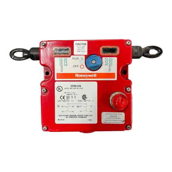
Installation Instructions for the Cable Pull Safety Switch (2CPS Series)
Instrucciones de instalación para el interruptor de seguridad de tracción de cable (Serie 2CPS)
Einbauanweisungen für Sicherheitsseilzugschalter (Serie 2CPS)
Instructions d'installation de l'interrupteur de sécurité à câble (série 2CPS)
Istruzioni di installazione per l'interruttore di sicurezza con cavo di azionamento (serie 2CPS)
Instruções de instalação para a chave de segurança acionada por tração de cabo (série 2CPS)
WARNING
IF USED IN APPLICATIONS CONCERNING HUMAN
SAFETY
• Only use NC direct opening ("positive opening"/"positive
break") contacts, identified by the symbol
• Do NOT use flexible/adjustable actuators. Only use
actuators designed for safety applications.
• Do NOT defeat, tamper, remove, or bypass this switch.
• Hazardous voltage, disconnect power before servicing.
• Strictly adhere to all installation and maintenance
instructions.
• Consult with local safety agencies and their requirements
when designing a machine-control link, interface and all
control elements that affect safety.
Failure to comply with these instructions could result
in death or serious injury.
WARNING
IMPROPER USE
• Use the 2CPS Cable Pull Safety Switch in emergency
stop applications only. Do not use in general production
stop applications.
Failure to comply with these instructions could result
in death or serious injury.
WARNING
IMPROPER SYSTEM PERFORMANCE
• The 2CPS Cable Pull Safety Switch provides only the
front end switching/sensing function. The machine, its
external machine interfaces, and the safety monitoring of
the machine and its interfaces, are the responsibility of
the machine safety control system.
• The user is SOLELY RESPONSIBLE for determining the
appropriate level of risk.
• The 2CPS Cable Pull Safety Switch must be installed in
a fashion that complies with all codes and standards that
are applicable to the particular application of the device.
EN 1050 and ANSI TR3 Risk Assessment and Risk
Reduction provide assistance on how to perform risk
assessment.
Failure to comply with these instructions could result
in death or serious injury.
GENERAL INFORMATION
• The 2CPS is available in either single actuator or dual
actuator versions. The maximum cable length in a single
direction is 76 m [250 ft] for a combined length of 152 m
[500 ft] in dual directions.
Sensing and Control
®
• The direct acting switch contacts are held closed when the
actuating cable is under proper tension and the reset knob
is set to RUN. When the actuating cable is pulled,
slackened or broken, a cam positively opens the NC
(Normally Closed) switch contacts. The snap action, trip
.
operation causes the switch contacts to change state and
mechanically latch almost simultaneously when the cable
is pulled, slackened or broken. The NC switch contacts
remain open until the 2CPS is reset by properly tensioning
the cable and manually rotating the reset knob.
• When the direct acting switch contacts open, the auxiliary
contacts also actuate (open contacts close and closed
contacts open). The auxiliary contacts are electrically
isolated from the direct acting switch contacts. These NO
(Normally Open) contacts may be used for monitoring or
signaling.
• A removable contact block version is available for robust
and easy termination.
• Hardware packets are available separately (see Table 1
on page 13).
STEP 1: MOUNT, WIRE AND SEAL SWITCH
IMPROPER OPERATION
• Locate the 2CPS such that the installed cable is visible
from the 2CPS reset OR inspect the length of the cable
whenever a stop is signaled.
• Ensure no barriers or physical obstructions prevent the
operator from actuating the 2CPS Cable Pull Safety
Switch.
Failure to comply with these instructions could result
in death or serious injury.
A. Refer to pages 14-19 for:
• Specifications (Table 2).
• Mounting dimensions (Figure 1).
• Wiring configurations and travel distances Figure 2).
• Installation drawings (Figures 3, 4, 5).
B. Mount switch using four M6, 1/4-28 UNF or 1/4-20 UNC
screws or bolts. Torque:
• M6 to 6,1 N m–7,5 N m [54 in lb–66 in lb].
• 1/4-28 UNF to 8,6 N m–10,4 N m [76 in lb–92 in lb].
• 1/4-20 UNC to 7,3 N m–9,0 N m [65 in lb–79 in lb].
C. Refer to the circuit diagram on the switch cover. The
diagram depicts the switch contacts when the cable(s) is
(are) at proper tension and the reset knob is in the RUN
position.
D. Remove the cover plate.
PK 80155
WARNING
Issue 5
Werbung

Verwandte Anleitungen für Honeywell 2CPS Series


Inhaltszusammenfassung für Honeywell 2CPS Series
- Seite 1 Issue 5 PK 80155 ® Installation Instructions for the Cable Pull Safety Switch (2CPS Series) Instrucciones de instalación para el interruptor de seguridad de tracción de cable (Serie 2CPS) Einbauanweisungen für Sicherheitsseilzugschalter (Serie 2CPS) Instructions d’installation de l’interrupteur de sécurité à câble (série 2CPS) Istruzioni di installazione per l’interruttore di sicurezza con cavo di azionamento (serie 2CPS)
- Seite 2 • When changing the actuating cable direction, i.e., around machinery should be inspected along the entire length of a corner, ensure the cable runs freely through a pulley or the actuating cable in order to determine the reason for cable supports. actuation. 2 Honeywell • Sensing and Control...
-
Seite 3: Información General
G. Selle la abertura del conducto eléctrico según las instrucciones dadas en PK 80112 (incluidas). H. Vuelva a montar la tapa. Ajuste los tornillos de la tapa hasta 1,5 N m (13 lbf·pulg.). Honeywell • Sensing and Control 3... - Seite 4 ±8 °C [±15 °F]. • Para cumplir con las normas, instale un interruptor de tracción de cable en cada extremo del cable o un resorte extremo al final del cable opuesto al interruptor. 4 Honeywell • Sensing and Control...
- Seite 5 H. Die Deckplatte wieder montieren. Die missbrauchsicheren Anziehen, Lockern oder Reißen des Seils. Die Öffner- Deckelschrauben mit 1,5 Nm anziehen. Schaltkontakte bleiben geöffnet, bis der Schalter 2CPS durch entsprechendes Spannen des Seils und manuelles Drehen des Rücksetzknopfes zurückgesetzt wird. Honeywell • Sensing and Control 5...
- Seite 6 − Ringe für sämtliche Anschlusstypen − Zugentlastungsklemmen für sämtliche Anschlusstypen − Endfeder für sämtliche Anschlusstypen • Endfeder analog zu den Schritten 2.C und 2.D am dem Schalter gegenüberliegenden Seilende einbauen. • Endfeder an eine feste Halterung anbringen. 6 Honeywell • Sensing and Control...
- Seite 7 PK 80112 (inclues). tension correcte du câble et une rotation manuelle du H. Remontez le couvercle. Serrez les vis inviolables du bouton de réarmement permettent de réarmer le 2CPS. couvercle avec un couple de 1,5 N.m. Honeywell • Sensing and Control 7...
- Seite 8 ±8 °C. • Par souci de conformité aux normes, installez un interrupteur à câble à chaque extrémité du câble ou un ressort d'extrémité à l'extrémité du câble la plus éloignée de l'interrupteur. 8 Honeywell • Sensing and Control...
- Seite 9 PK 80112 (allegato). manualmente la manopola di ripristino. H. Rimontare la piastra di copertura. Serrare le viti antimanomissione del coperchio a 1,5 Nm (13 pollici-libbre). Honeywell • Sensing and Control 9...
- Seite 10 è pari a ±8 °C[±15 °F]. • Per conformità con le norme, installare un interruttore trainato a cavo a ciascuna estremità del cavo o una molla terminale all'estremo opposto del cavo dall'interruttore. 10 Honeywell • Sensing and Control...
- Seite 11 2CPS seja reinicializada pelo instruções encontradas no PK 80112 (incluído). tensionamento adequado do cabo e rotação manual do H. Reinstale a tampa de cobertura. Aperte os parafusos a botão de reinicialização. 1,5 N.m (4,4 pol. lb). Honeywell • Sensing and Control 11...
- Seite 12 − Molas de extremidade para encaixe em todas as terminações. • Instale uma mola de extremidade no cabo oposto à chave da mesma forma que nos Passos 2.C e 2.D. • Conecte a mola a um suporte fixo. 12 Honeywell • Sensing and Control...
- Seite 13 (1) LED 24 Vcc multicluster CPSLED24 groupes da 24 VCC • • • (1) LED 120 V a.c. multi- (1) LED contatti di uscita multipli (1) LED 120 Vca multicluster CPSLED120 groupes da 120 VCA Honeywell • Sensing and Control 13...
- Seite 14 • Approvato da BG • Aprovado pela BG. • EN418: Conformité EN418 – voir l’étape 4. • Conformità EN418 – Vedere fase 4. • De acordo com os padrões da EN418 – consulte a Etapa 4. 14 Honeywell • Sensing and Control...
- Seite 15 C Scanalatura di guida (3 in totale) C Passagem de conduíte (total de 3) (3 emplacements) D Piastra di montaggio (4 in totale) D Suporte de montagem (total de 4) D Patte de montage (4 emplacements) Honeywell • Sensing and Control 15...
- Seite 16 G Tensão do cabo = 133 N H Tensione cavo = 178 N (40 libbre) H Tensão do cabo = 178 N Contatto chiuso Contato fechado Contatto aperto Contato aberto * Apertura positiva IEC/EN60947-5-1 * Abertura positiva para IEC/EN60947-5-1 16 Honeywell • Sensing and Control...
- Seite 17 Versione con blocco contatti Versão de bloco de contato standard A Parafuso terra amovibile per cablaggi di removível com fiação A Vite di massa potenza resistente a desgaste A Vite di massa A Parafuso terra Honeywell • Sensing and Control 17...
- Seite 18 Distanziale Braçadeira de cabo G Support de câble (boulon à œil) Morsetto serrafilo G Suporte de cabo (parafuso Ressort d’extrémité G Supporto per cavo (bullone a com olhal) occhiello) Mola de extremidade Molla terminale 18 Honeywell • Sensing and Control...
- Seite 19 – o cabo direito está droit est correctement tendu destro è correttamente teso com a tensão correta D Cosse D Distanziale D Sapatilha E Serre-câble E Morsetto serrafilo E Braçadeira de cabo F Câble F Cavo F Cabo Honeywell • Sensing and Control 19...
- Seite 20 While we provide application assistance personally, through responsabilidad alguna por su uso. our literature and the Honeywell web site, it is up to the customer Aunque Honeywell ofrece soporte para las aplicaciones de to determine the suitability of the product in the application.