Regin CMF5U Anleitung
Inhaltsverzeichnis
Verfügbare Sprachen
Verfügbare Sprachen
Quicklinks
INSTRUCTION
EN
CMF5U
i
Read this instruction before installation
and wiring of the product
Consult documentation in all cases where this symbol
is used, in order to find out the nature of the potential
hazards and any actions to be taken
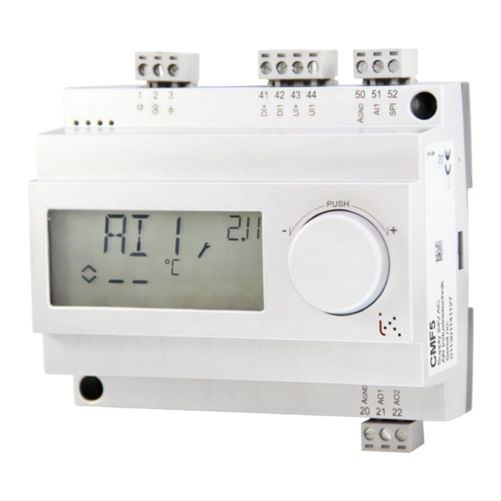
Controller with display
CMF5U is a pre-programmed, configurable controller. It has 5 inputs/
outputs and can be configured to control temperature, CO
or pressure. All configuration and normal handling is done using the
display and the knob on the front. From revision R18, it is possible to
connect an external PT1000 setpoint device.
Technical data
Supply voltage
24 V AC ±15%, 50...60 Hz
Power consumption
3 VA
Ambient temperature
0...50°C
Ambient humidity
Max. 90% RH
Storage temperature
-20...70°C
Display
Numeric / graphic. Background
illumination.
Inputs/outputs
Terminal blocks
Protection class
Material, casing
Weight
Dimensions
Pollution degree
Temperature settings
Temperature, supply air
Setpoints
External setpoint
Neutral zone
P-band
I-time
Min. limit damper
Other settings
Setpoint values
CO
2
General (GEN)
Pressure (Pa)
Scaling of UI1
CO
2
General
Pressure
Neutral zone
P-band
CO
2
General (RH)
, humidity
Pressure (Pa)
2
I-time
Control setting 5
Outdoor compens. start
Setpoint pressure at
-20°C outdoor temp.
Refer to connection illustrations and
table below
Disconnectable, so-called lift type for
cable cross-section max 2.5 mm
2
IP20
Polycarbonate, PC
215 g incl. terminal blocks
122 x 120 x 64 mm (WxHxD incl. terminals,
fixed installation)
2
-20..+60, 20...100, 60...140°C
-18...+60, 22...100, 62...140°C
0...40°C
0...10°C
0...99°C
0...990 s
0...99%
0...100% of max set value on UI1
0...100% of max set value on UI1
0...100% of max set value on UI1
0...10 V DC in
10...9900 ppm
0...100%
100 Pa...2500 kPa
12.5% of max
0...100% of UI1
0...100% of UI1
0...300% of UI1
0...990 s
-20...+60°C
0 Pa...2500 kPa
CMF5U
Installation
CMF5U must be mounted in a DIN-standard casing (minimum 7
modules) or in a cabinet, either on a DIN-rail or, using the two screw-
pockets provided, by being screwed to any suitable flat surface in the
cabinet. The controller can also be mounted in a cabinet door or other
control panel, using a suitable front-mounting kit (CMF-KIT).
The controller must be connected to a 24 V AC safety insulating
transformer providing mains insulation.
Follow table 1 below for connection.
Table 1. I/O connection terminals. Terminals 2, 20 and 50 are internally con-
nected.
Terminal
Designation
Operation
1
G
Supply voltage 24 V AC
2
G0
3
20
AGnd
Ref. for AO1 and AO2
21
AO1
0...10 V DC Output
22
AO2
0...10 V DC Output
41
DI+
Reference for DI1
42
DI1
Digital input
43
UI+
Reference for UI1 digital mode
44
UI1
0...10 V DC or Digital input
50
AGnd
Ref. for AI1, SPI and UI1 analogue
51
AI1
PT1000 temp. sensor input
52
SPI
Input PT1000 setpoint device
Digital inputs DI and UI are only intended to be used with a
potential-free contact or switch. If the CMF5U and active sensors and
actuators connected to it share transformer, it is essential that the
same transformer-pole is used as reference for all the equipment.
Failure to do so will prevent the equipment from functioning as
intended and may also lead to damages.
For best protection against disturbances, a shielded twisted-pair cable
should be used for wiring the sensors. Ground the shield at one end.
The protection provided by the equipment may be impaired by im-
proper use.
1
Inhaltsverzeichnis

Verwandte Anleitungen für Regin CMF5U


Inhaltszusammenfassung für Regin CMF5U
-
Seite 11: Regler Mit Display
(mode de régul. 1 seulement) Installation Versorgungsspannung 24 V AC ±15%, 50...60 Hz CMF5U kann in ein DIN Standardgehäuse (mind. 7 Module) montiert Revenir aux réglages par défaut (réglages usine) Stromverbrauch 3 VA werden oder in einem Schaltschrank - entweder auf eine DIN- Umgebungstemperatur 0...50°C... - Seite 12 Die digitalen Eingänge und UI sind nur für die Verwendung Start- mit einem potentialfreien Kontakte oder Schalter vorgesehen. signal °C Werden der CMF5U und die angeschlossenen aktiven Fühler und Stellantriebe vom gleichen Transformator gespeist, muss als Befeuchter % RF Feuchte- Bezugsmasse immer der gleiche Transformatorpol für die gesamte...
-
Seite 13: Das Display-Menüsystem
Aufrufen des Konfigurationsmenüs. Regler bei Drücken den Drehknopfs das Basismenüdisplay anzeigen. temperatur- kompensation Für weitere Informationen über das Konfigurationsmenü im 10-Sekunden-Menü, siehe das “CMF5U Handbuch”. Das Basismenü Maximale Falls keine Eingaben erfolgen, wird das Basisdisplay angezeigt. Kompensation Tabelle 2 unten zeigt die Anordnung des 10-Sekunden-Menüs. Wenn das 10-Sekunden-Menü... -
Seite 14: Zurücksetzen Auf Werkseinstellungen
Zurücksetzen auf Werkseinstellungen Das Symbol “Menü mit veränderbaren Werten” ( )beginnt zu blinken. Den Wert durch Drehen des Knopfes ändern und die Änderung durch CMF5U kann auf die Werkseinstellungen zurückgesetzt werden, indem Feuchteregelung konfiguriert (Regelmodus 3), der Transmit- Drücken des Knopfes bestätigen.