Gemü 656 Original Einbau- Und Montageanleitung
Tiefsitzmembranventil metall, dn 25 - 250
Vorschau ausblenden
Andere Handbücher für 656:
- Betriebsanleitung (72 Seiten) ,
- Original einbau- und montageanleitung (40 Seiten) ,
- Original einbau- und montageanleitung (40 Seiten)

Verwandte Anleitungen für Gemü 656


Inhaltszusammenfassung für Gemü 656
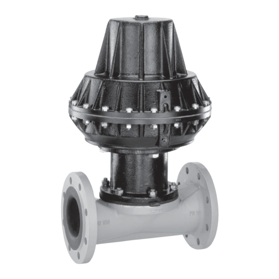
- Seite 1 Tiefsitzmembranventil Metall, DN 25 - 250 Full Bore Diaphragm Valve Metal, DN 25 - 250 ORIGINAL EINBAU- UND MONTAGEANLEITUNG INSTALLATION, OPERATING AND MAINTENANCE INSTRUCTIONS...
-
Seite 2: Inhaltsverzeichnis
Inhaltsverzeichnis Allgemeine Hinweise Voraussetzungen für die einwandfreie Allgemeine Hinweise Funktion des GEMÜ-Ventils: Allgemeine Sicherheitshinweise 2 Sachgerechter Transport und Lagerung Hinweise für Service- Installation und Inbetriebnahme durch und Bedienpersonal eingewiesenes Fachpersonal Warnhinweise Bedienung gemäß dieser Einbau- und Verwendete Symbole Montageanleitung Begriff sbestimmungen Ordnungsgemäße Instandhaltung Vorgesehener Einsatzbereich Technische Daten... -
Seite 3: Hinweise Für Service
Hinweise für Service- Warnhinweise und Bedienpersonal Warnhinweise sind, soweit möglich, nach folgendem Schema gegliedert: Die Einbau- und Montageanleitung enthält grundlegende Sicherheitshinweise, die bei SIGNALWORT Inbetriebnahme, Betrieb und Wartung zu beachten sind. Nichtbeachtung kann zur Art und Quelle der Gefahr Folge haben: ®... -
Seite 4: Verwendete Symbole
Vorgesehener Verwendete Symbole Einsatzbereich Gefahr durch heiße Oberfl ächen! Das Tiefsitzmembranventil GEMÜ 656 ist für den Einsatz in Rohrleitungen Gefahr durch ätzende Stoff e! konzipiert. Es steuert ein durchfl ießendes Medium indem es durch ein Steuermedium geschlossen oder Quetschgefahr! geöff net werden kann. -
Seite 5: Technische Daten
Technische Daten Steuermedium Betriebsmedium Neutrale Gase Aggressive, neutrale, gasförmige und flüssige Medien, die die physikalischen und chemischen Eigenschaften des Max. zul. Temp. des Steuermediums 40 °C jeweiligen Gehäuse- und Membranwerkstoffes nicht negativ beeinflussen. Füllvolumen Steuerfunktion 1 - 3: Antriebsgröße 2R2, 2RF, 2RD 0,625 dm³... - Seite 6 Steuer- / Betriebsdruckdiagramm Hinweis: In den Diagrammen werden zwei Kennlinien angegeben: maximaler Steuerdruck und empfohlener Steuerdruck. Der von GEMÜ empfohlene Steuerdruck ist optimal für die jeweiligen Betriebsbedingungen ausgelegt. Das Ventil kann auch bis zum maximalen Steuerdruck betrieben werden, jedoch wirkt sich ein zu hoher Steuerdruck negativ auf die Lebensdauer der Membran aus. Für die Begrenzung des Steuerdrucks empfehlen wir die Verwendung eines Druckminderers (Artikelnummer: 88275629).
-
Seite 7: Bestelldaten
Bestelldaten Gehäuseform Code Steuerfunktion Code Durchgang Federkraft geschlossen (NC) Federkraft geöffnet (NO) Beidseitig angesteuert (DA) Anschlussart Code Flansch EN 1092 / PN10 / Form A, Baulänge FTF EN 558, Reihe 7, ISO 5752, basic series 7 Antriebsausführung Code Flansch EN 1092 / PN16 / Form A, Baulänge FTF EN 558, Reihe 7, Für Federkraft geschlossen (Code 1) ISO 5752, basic series 7... -
Seite 8: Herstellerangaben
Herstellerangaben Funktionsbeschreibung GEMÜ 656 ist ein 2/2-Wege- Transport Metall-Tiefsitzmembranventil mit Durchgangskörper. Das Ventil besitzt einen Ventil nur auf geeignetem Lademittel wartungsarmen Membranantrieb, der mit transportieren, nicht stürzen, vorsichtig neutralen Gasen angesteuert werden kann. handhaben. Es stehen die Steuerfunktionen "Federkraft Verpackungsmaterial entsprechend geschlossen", "Federkraft geöffnet"... -
Seite 9: Montage Und Anschluss
Montage und Anschluss Installationsort: VORSICHT Vor Einbau: Ventilkörper- und Membranwerkstoff Ventil äußerlich nicht stark entsprechend Betriebsmedium auslegen. beanspruchen. Eignung vor Einbau prüfen! Installationsort so wählen, dass Ventil Siehe Kapitel 5 "Technische Daten". nicht als Steighilfe genutzt werden kann. 10.1 Montage des Ventils Rohrleitung so legen, dass Schub- und Biegungskräfte, sowie Vibrationen WARNUNG... -
Seite 10: Steuerfunktionen
Montage bei Flanschanschluss: Steuerfunktion 3 1. Auf saubere und unbeschädigte Beidseitig angesteuert (DA): Dichtfl ächen der Anschlussfl ansche Ruhezustand des Ventils: keine definierte achten. Grundposition. Öffnen und Schließen des 2. Flansche vor Verschrauben sorgfältig Ventils durch Ansteuern der entsprechenden ausrichten. Steuermediumanschlüsse (Anschluss 2: 3. -
Seite 11: Steuermedium Anschließen
10.3 Steuermedium anschließen 11.1 Demontage Ventil (Antrieb vom Körper lösen) Wichtig: 1. Antrieb A in Off en-Position bringen. Steuermediumleitungen 2. Antrieb A vom Ventilkörper 1 spannungs- und knickfrei demontieren. montieren! 3. Antrieb A in Geschlossen-Position Je nach Anwendung geeignete bringen. Anschlussstücke verwenden. -
Seite 12: Montage Membrane
11.3 Montage Membrane DN 25 - 40: Druckstück und Antriebsflansch von unten gesehen: 11.3.1 Allgemeines Wichtig: Für Ventil passende Membrane einbauen (geeignet für Medium, Mediumkonzentration, Temperatur und Druck). Die Membrane ist ein Verschleißteil. DN 50 - 65: Vor Inbetriebnahme und über Druckstück und Antriebsflansch von unten gesamte Einsatzdauer des Ventils gesehen:... -
Seite 13: 11.3.2 Montage Der Tiefsitzmembrane
DN 200: beschrieben. Druckstück und Antriebsflansch von unten 2. Antrieb A in Geschlossen-Position gesehen: bringen. 3. Membranpin der neuen Membrane von Hand in Druckstück des Antriebs einschrauben. Beim Verspüren eines deutlichen Widerstands Membrane soweit zurückschrauben, bis Membran- Lochbild und Antriebs-Lochbild übereinstimmt. -
Seite 14: Inbetriebnahme
Inbetriebnahme Inspektion und Wartung WARNUNG WARNUNG Aggressive Chemikalien! Unter Druck stehende Armaturen! ® Verätzungen! ® Gefahr von schwersten Verletzungen Vor Inbetriebnahme Dichtheit oder Tod! der Medienanschlüsse Nur an druckloser Anlage arbeiten. prüfen! VORSICHT Dichtheitsprüfung nur mit geeigneter Heiße Anlagenteile! Schutzausrüstung. ®... -
Seite 15: Demontage
Demontage Hinweise Demontage erfolgt unter den gleichen Hinweis zur Vorsichtsmaßnahmen wie die Montage. Mitarbeiterschulung: Ventil demontieren (siehe Kapitel 11.1 Zur Mitarbeiterschulung nehmen "Demontage Ventil (Antrieb vom Körper Sie bitte über die Adresse auf der lösen)"). letzten Seite Kontakt auf. Im Zweifelsfall oder bei Missverständnissen Entsorgung ist die deutsche Version des Dokuments ausschlaggebend! -
Seite 16: Fehlersuche / Störungsbehebung
Fehlersuche / Störungsbehebung Fehler Möglicher Grund Fehlerbehebung Steuermedium entweicht aus Entlüftungsbohrung* im Oberteil des Antriebs Steuermembrane* defekt Antrieb austauschen bei Steuerfunktion NC bzw. Anschluss 2* bei Steuerfunktion NO Steuermedium entweicht Antrieb austauschen und Steuermedium Spindelabdichtung undicht aus Leckagebohrung* auf Verschmutzungen untersuchen Betriebsmedium entweicht Membrane auf Beschädigungen prüfen, Membrane defekt... -
Seite 17: Schnittbild Und Ersatzteile
Schnittbild und Ersatzteile Entlüftungs bohrung Steuermembrane Anschluss 2 Leckagebohrung Pos. Benennung Bestellbezeichnung Ventilkörper K655… Tiefsitzmembrane 655…M… Schraube Scheibe 655...S30... Mutter Antrieb 9656... 17 / 40... -
Seite 18: Einbauerklärung
29.12.2009 Projektnummer: MV-Pneum-2009-12 Handelsbezeichnung: Typ 656 Es wird erklärt, dass die folgenden grundlegenden Anforderungen der Maschinenrichtlinie 2006/42/EG erfüllt sind: 1.1.3.; 1.1.5.; 1.1.7.; 1.2.1.; 1.3.; 1.3.2.; 1.3.3.; 1.3.4.; 1.3.7.; 1.3.9.; 1.5.3.; 1.5.5.; 1.5.6.; 1.5.7.; 1.5.8.; 1.5.9.; 1.6.5.; 2.1.1.; 3.2.1.; 3.2.2.; 3.3.2.; 3.4.4.; 3.6.3.1.; 4.1.2.1.; 4.1.2.3.; 4.1.2.4.; 4.1.2.5.; 4.1.2.6. a); 4.1.2.6. b);... -
Seite 19: Eu-Konformitätserklärung
GEMÜ Gebr. Müller Apparatebau GmbH & Co. KG Fritz-Müller-Straße 6-8 D-74653 Ingelfingen erklären, dass unten aufgeführte Armaturen die Sicherheitsanforderungen der Druckgeräte- richtlinie 2014/68/EU erfüllen. Benennung der Armaturen - Typenbezeichnung Tiefsitzmembranventil GEMÜ 656 Benannte Stelle: TÜV Rheinland Industrie Service GmbH Nummer: 0035 Zertifikat-Nr.: 01 202 926/Q-02 0036... - Seite 38 38 / 40...
- Seite 39 39 / 40...
- Seite 40 GEMÜ Gebr. Müller Apparatebau GmbH & Co. KG · Fritz-Müller-Str. 6-8 · D-74653 Ingelfi ngen-Criesbach Telefon +49(0)7940/123-0 · Telefax +49(0)7940/123-192 · info@gemue.de · www.gemu-group.com...