
Verwandte Anleitungen für Abit SI7-Serie


Inhaltszusammenfassung für Abit SI7-Serie
- Seite 1 SI7 Series (SI7, SI7-G) Socket 478 System Board User’s Manual 4200-0346-02 Rev. 1.00...
- Seite 2 Copyright and Warranty Notice The information in this document is subject to change without notice and does not represent a commitment on part of the vendor, who assumes no liability or responsibility for any errors that may appear in this manual. No warranty or representation, either expressed or implied, is made with respect to the quality, accuracy or fitness for any particular part of this document.
-
Seite 3: Inhaltsverzeichnis
Table Of Contents SI7 系列快速安裝指引 ................1 SI7 シリーズのクイックインストールガイド ........3 SI7-Serie Schnellinstallationsanleitung ..........5 Série SI7 Guide d’Installation Rapide............ 7 Краткое руководство по установке SI7 cерия ........9 Guida all’installazione veloce Scheda madre serie SI7......11 Chapter 1. Introduction ................1-1 1-1. - Seite 4 Chapter 3. BIOS Setup................3-1 3-1. SoftMenu Setup Features .................3-2 3-2. Standard CMOS Features.................3-4 3-3. Advanced BIOS Features.................3-6 3-4. Advanced Chipset Features..............3-8 3-5. Power Management Features ..............3-10 3-6. PnP/PCI Configurations.................3-13 3-7. Integrated Peripherals ................3-16 3-8. PC Health Status ..................3-21 3-9. Set Password ..................3-22 3-10.
-
Seite 5: Si7 系列快速安裝指引
SI7 系列快速安裝指引 SI7 系列快速安裝指引 處理器的安裝 (Zero Insertion Force, ZIF) ® ® Socket 478 Intel Pentium 4 CPU ® Pentium 4 Socket 478 Socket 478 ® 注意: Pentium 注意: User’s Manual... - Seite 6 SI7 系列快速安裝指引 將主機板安裝到機殼上 安裝系統記憶體 RIMM RIMM 128MB RIMM RIMM 何 RIMM 卡榫 種 保 RIMM 僅 RIMM RIMM RIMM 退 RIMM 自 卡 地 連接器、連接頭以及附加卡的安裝 任何 部 必需連接 些纜 頭 些纜 頭通常 連接 連接埠 必需 任何 條纜 連接 併 連接埠 根針...
-
Seite 7: Si7 シリーズのクイックインストールガイド
SI7 シリーズのクイックインストールガイド SI7 シリーズのクイックインストールガイド な利 マ ニュアルはこのマザーボードによって詰められて来たドライバとユーティリティの CD の拾い 読みによって利 できる プロセッサの取り付け ZIF ( ® ® ) Socket 478 Intel Pentium 4 CPU ® Pentium 4 Socket 478 1. Socket 478 ® 注意:Pentium 2. CPU User’s Manual... - Seite 8 SI7 シリーズのクイックインストールガイド 注意:プロセッサに対して、正しいバス周波数とマルチプルに設定することを忘れないでください。 マザーボードをシャーシに取り付ける システムメモリの取り付け RIMM 128MB 2GB RIMM RIMM RIMM RIMM RIMM RIMM コネクタ、ヘッダ、スイッチおよびアダプタ SCSI 電源コネクタを ATX12V 電源コネクタに差し込む ATX12V BIOS のセットアップ BIOS Setup SI7 Series...
-
Seite 9: Si7-Serie Schnellinstallationsanleitung
SI7-Serie Schnellinstallationsanleitung SI7-Serie Schnellinstallationsanleitung Beziehen Sie sich bitte für detaillierte Informationen über diese Hauptplatine auf die vollständige Version des Benutzerbuchs. Diese Schnellinstallationsanleitung ist für erfahrene Systemaufbauer gedacht. Ist es Ihr erster Versuch ein Computersystem aufzubauen, dann empfehlen wir Ihnen zuerst das vollständige Benutzerhandbuch zu lesen oder einen Techniker zum Aufbauen des Systems zu Hilfe zu holen (A complete user’s manual is available via browsing the Driver &... - Seite 10 SI7-Serie Schnellinstallationsanleitung Achtung: Vergessen Sie nicht, die korrekte Busfrequenz und Multiplikator für Ihren Prozessor einzustellen. Installieren der Hauptplatine im Gehäuse Nach der Installation des Prozessors können Sie anfangen die Hauptplatine im Computergehäuse zu befestigen. Die meisten Gehäuse haben eine Bodenplatte, auf der sich eine Reihe von Befestigungslöcher befinden, mit deren Hilfe Sie die Hauptplatine sicher verankern können und zugleich Kurzschlüsse...
-
Seite 11: Série Si7 Guide D'installation Rapide
Série SI7 Guide d’Installation Rapide Série SI7 Guide d’Installation Rapide Pour des informations relatives à cette carte mère plus détaillées, veuillez vous référer à notre version complète du manuel utilisateur. Ce guide d’installation rapide est créé pour les assembleurs système expérimentés. - Seite 12 Série SI7 Guide d’Installation Rapide 6. Le couvercle support et la base du dissipateur thermique doivent maintenant être fermement fixés l'un à l'autre fermement avec le dissipateur thermique à l'intérieur. Attention: N'oubliez pas de régler une fréquence de Bus et un coefficient multiplicateur corrects pour votre processeur.
-
Seite 13: Краткое Руководство По Установке Si7 Cерия
Краткое руководство по установке SI7 cерия Краткое руководство по установке SI7 cерия Более подробные сведения о материнской плате приведены в руководстве пользователя. Краткое руководство по установке предназначено для опытных специалистов. Если вы собираете компьютер впервые, ознакомьтесь сперва с руководством пользователя или попросите техника помочь... - Seite 14 Краткое руководство по установке SI7 cерия Установка материнской платы в корпус После установки процессора на материнскую плату можно начинать установку материнской платы в корпус. Большая часть корпусов оборудована основанием, в котором проделаны монтажные отверстия, которые позволяют надежно закрепить материнскую плату и предотвратить короткие...
-
Seite 15: Guida All'installazione Veloce Scheda Madre Serie Si7
Guida all’installazione veloce Scheda madre serie SI7 Guida all’installazione veloce Scheda madre serie SI7 Per maggiori e dettagliate informazioni su questa scheda madre si prega di fare riferimento alla versione integrale del Manuale utente. Questa guida all’installazione veloce è intesa per costruttori esperi di sistemi. - Seite 16 Guida all’installazione veloce Scheda madre serie SI7 Attenzione: Non dimenticare di impostare la corretta frequenza BUS e multiplier per il processore. Installazione della scheda madre sul telaio Dopo avere installato il processore sulla scheda madre si può iniziare a fissare la scheda madre sul telaio. Innanzi tutto è...
-
Seite 17: Chapter 1. Introduction
Introduction Chapter 1. Introduction 1-1. Features & Specifications 1. CPU ® ® • Supports Intel Pentium 4 socket 478 processor with 400MHz/533MHz System Data Bus ® • Supports Intel Hyper-Threading Technology 2. Chipset • SiS R658 + SiS 963 • Supports Hi-Speed Universal Serial Bus (USB 2.0) •... -
Seite 18: Order Information
Chapter 1 • Supports Advanced Configuration Power Interface (ACPI) • Supports Desktop Management Interface (DMI) • AMI BIOS 12. Internal I/O Connectors • 1x AGP slot • 5x PCI slots • 1x Floppy port supports up to 2.88MB • 2x Ultra ATA/133/100/66/33 connectors •... -
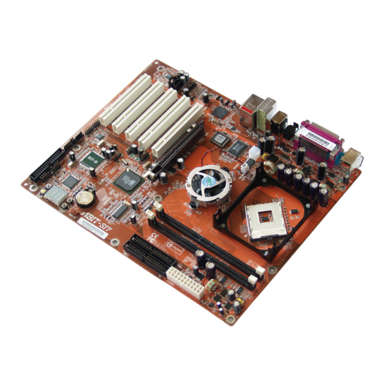
Seite 19: Layout Diagram
Introduction 1-2. Layout Diagram User’s Manual... - Seite 20 Chapter 1 Chapter 1 SI7 Series SI7 Series...
-
Seite 21: Chapter 2. Hardware Setup
Hardware Setup Chapter 2. Hardware Setup Before the Installation: Turn off the power supply switch (fully turn off the +5V standby power), or disconnect the power cord before installing or unplugging any connectors or add-on cards. Failing to do so may cause the motherboard components or add-on cards to malfunction or damaged. 2-1. - Seite 22 Chapter 2 ® 2-2. Install Pentium 4 CPU and Heatsink Supporting-Base This motherboard provides a ZIF (Zero Insertion ® ® Force) Socket 478 to install Intel Pentium CPU. The CPU you bought should have a kit of heatsink and cooling fan along with. If that’s not ®...
-
Seite 23: Install System Memory
Hardware Setup 2-3. Install System Memory This motherboard provides two 232-pin 32-bit RIMM (Rambus Inline Memory Modules) slots for PC1200/PC1066/PC800 Direct RDRAM. ATTENTION: The PC1066 RIMM modules require CPU of 533MHz FSB only. Do not use PC1066 modules with CPU of 400MHz FSB. Table 2-1. - Seite 24 Chapter 2 The diagram below shows the possible combination of RDRAM installation. NOTE: No hardware or BIOS setup required after adding or removing memory modules. ATTENTION: Static electricity can damage the electronic components of the computer or optional boards. Before starting these procedures, ensure that you are discharged of static electricity by touching a grounded metal object briefly.
-
Seite 25: Connectors, Headers And Switches
Hardware Setup 2-4. Connectors, Headers and Switches Here we will show you all of the connectors, headers and switches, and how to connect them. Please read the entire section for necessary information before attempting to finish all the hardware installation inside the computer chassis. -
Seite 26: Fan Connectors [Cpufan1, Sysfan1, Auxfan1]
Chapter 2 (2). FAN Connectors [CPUFAN1, SYSFAN1, AUXFAN1] These 3-pin connectors each provide power to the cooling fans installed in your system. The CPU must be kept cool by using a powerful fan with heatsink. The system is capable of monitoring the speed of the CPU fan. -
Seite 27: Cmos Memory Clearing Header [Ccmos1]
Hardware Setup (3). CMOS Memory Clearing Header [CCMOS1] This header uses a jumper cap to clear the CMOS memory. • Pin 1-2 shorted (default): Normal operation. • Pin 2-3 shorted: Clear CMOS memory. WARNING: Turn the power off first (including the +5V standby power) before clearing the CMOS memory. -
Seite 28: Front Panel Audio Connection Header [Fp-Audio1]
(4). Front Panel Audio Connection Header [FP-AUDIO1] This header provides the connection to audio connector at front panel (with optional ABIT Media XP). • To use the audio connector at front panel, remove all the jumpers on this header, and then connect to front panel by the extension cable provided with the chassis. -
Seite 29: Additional Usb Port Headers [Fp-Usb1, Fp-Usb2]
Hardware Setup (5). Additional USB Port Headers [FP-USB1, FP-USB2] These headers each provide 2 additional USB 2.0 ports connection through an USB cable designed for USB 2.0 specifications. Pin Assignment Pin Assignment Data0 - Data1 - Data0 + Data1 + Ground Ground User’s Manual... -
Seite 30: Additional Ieee1394 Port Headers [Fp-1394-1, Fp-1394-2]
2-10 Chapter 2 (6). Additional IEEE1394 Port Headers [FP-1394-1, FP-1394-2] These headers each provide 1 additional IEEE1394 port connection through an extension cable and bracket. Pin Assignment Pin Assignment TPA0 + TPA0 - TPB0 + TPB0 - +12V +12V SI7 Series... -
Seite 31: Front Panel Switches & Indicators Headers [Fpio1]
Hardware Setup 2-11 (7). Front Panel Switches & Indicators Headers [FPIO1] This header is used for connecting switches and LED indicators on the chassis front panel. Watch the power LED pin position and orientation. The mark “+” align to the pin in the figure below stands for positive polarity for the LED connection. -
Seite 32: System Management Bus Header [Smb1]
2-12 Chapter 2 (8). System Management Bus Header [SMB1] This header is reserved for system management bus (SM bus). The SM bus is a specific implementation of an I C bus. I C is a multi-master bus, which means that multiple chips can be connected to the same bus and each one can act as a master by initiating a data transfer. -
Seite 33: Accelerated Graphics Port Slot [Agp1]
Hardware Setup 2-13 (10). Accelerated Graphics Port Slot [AGP1] This slot supports an optional AGP graphics card up to AGP 4X/8X mode. Please refer to our Web site for more information on graphics cards. ATTENTION: This motherboard does not support 3.3V AGP cards. Use only 1.5V or 0.8V AGP cards. User’s Manual... -
Seite 34: Floppy Disk Drive Connector [Fdc1]
2-14 Chapter 2 (11). Floppy Disk Drive Connector [FDC1] This connector supports two standard floppy disk drives via a 34-pin 34-conductor ribbon cable. Connecting the Floppy Disk Drive Cable: 1. Install one end of the ribbon cable into the FDC1 connector. The colored edge of the ribbon cable should be aligned with pin-1 of FDC1 connector. -
Seite 35: Ide Connectors [Ide1, Ide2]
Hardware Setup 2-15 (12). IDE Connectors [IDE1, IDE2] This motherboard provides two IDE ports to connect up to four IDE drives at Ultra ATA/100 mode by Ultra ATA/66 ribbon cables. Each cable has 40-pin 80-conductor and three connectors, providing two hard drives connection with motherboard. -
Seite 36: Serial Ata Connectors [Sata1, Sata2]
2-16 Chapter 2 (13). Serial ATA Connectors [SATA1, SATA2] These two connectors are provided to attach one serial ATA device at each channel through Serial ATA cable. It is also possible to connect legacy IDE hard disk through an optional SERILLEL Converter. SI7 Series... -
Seite 37: Post Code Display [U32]
Hardware Setup 2-17 (14). POST Code Display [U32] This is an LED device to display the “POST” Code, the acronym of Power On Self Test. The computer will execute the POST action whenever you power on the computer. The POST process is controlled by the BIOS. - Seite 38 2-18 Chapter 2 1. Disable PS/2 mouse interface (optional) 2. Auto detect ports for keyboard & mouse followed by a port & interface swap (optional) 3. Reset keyboard for Winbond 977 series Super I/O chips Test F000h segment shadow to see whether it is R/W-able or not. If test fails, keep beeping the speaker Auto detect flash type to load appropriate flash R/W codes into the run time area in F000 for ESCD &...
- Seite 39 Hardware Setup 2-19 1. Program MTRR of M1 CPU 2. Initialize L2 cache for P6 class CPU & program CPU with proper cacheable range 3. Initialize the APIC for P6 class CPU 4. On MP platform, adjust the cacheable range to smaller one in case the cacheable ranges between each CPU are not identical Initialize USB Test all memory (clear all extended memory to 0)
-
Seite 40: Onboard Switches [Forward, Back, Ps_On, Reset]
2-20 Chapter 2 1. Enable L2 cache 2. Program boot up speed 3. Chipset final initialization 4. Power management final initialization 5. Clear screen & display summary table 6. Program K6 write allocation 7. Program P6 class write combining 1. Program daylight saving 2. -
Seite 41: Status Indicators [D17, D14, D15, D18]
Hardware Setup 2-21 (16). Status Indicators [D17, D14, D15, D18] • D17 (FORWARD): This LED lights up when moving forward to next code layer of the POST Code Displayer. • D14 (BACK): This LED lights up moving backward to previous code layer of the POST Code Displayer. -
Seite 42: Back Panel Connectors [Km1, Lpt1, Com1, Com2, Opt-Out1, Audio1, Audio2, Lan, Usb1]
2-22 Chapter 2 (17). Back Panel Connectors [KM1, LPT1, COM1, COM2, OPT-OUT1, AUDIO1, AUDIO2, LAN, USB1] • Mouse: Connects to PS/2 mouse. • Keyboard: Connects to PS/2 keyboard. • LPT1: Connects to printer or other devices that support this communication protocol. •... -
Seite 43: Chapter 3. Bios Setup
BIOS Setup Chapter 3. BIOS Setup This motherboard provides a programmable EEPROM that you can update the BIOS utility. The BIOS (Basic Input/Output System) is a program that deals with the basic level of communication between processor and peripherals. Use the BIOS Setup program only when installing motherboard, reconfiguring system, or prompted to “Run Setup”. -
Seite 44: Softmenu Setup Features
Chapter 3 3-1. SoftMenu Setup Features The SoftMenu utility is ABIT’s exclusive and ultimate solution in programming the CPU operating speed. All the parameters regarding CPU FSB speed, multiplier factor, the AGP & PCI clock, and even the CPU core voltage are all available at your fingertips. - Seite 45 BIOS Setup There will be no guaranty for the settings beyond specification, any damage of any component on this motherboard or peripherals result therein is not our responsibility. CPU Front Side Bus Frequency: This item selects the FSB frequency for your CPU. The FSB speed above the CPU’s standard bus speed is supported but not guaranteed due to its specifications limit.
-
Seite 46: Standard Cmos Features
Chapter 3 3-2. Standard CMOS Features System Date: This item sets the date you specify (usually the current date) in the format of [Month], [Date], and [Year]. System Time: This item sets the time you specify (usually the current time) in the format of [Hour], [Minute], and [Second]. - Seite 47 BIOS Setup IDE Primary Master/Slave and IDE Secondary Master/Slave: Click <Enter> key to enter its submenu: Type: This item selects the type of your hard disk drives (HDD). Leave this option to its default [AUTO] settings to set all HDD parameters automatically. NOTE: A newly purchased IDE HDD must be first formatted.
-
Seite 48: Advanced Bios Features
Chapter 3 Block Mode: This option allows you to select [On] for a hard disk using block mode. The system BIOS will check the hard disk drive for the maximum block size the system can transfer. The block size will depend on the type of hard disk drive. - Seite 49 BIOS Setup How to use the Quick Boot function? When you start to get in the boot sequence, press <F6> key one time, then you can see the “Select First Boot Device” menu show up. Choose the first boot device you want then press <Enter> key to continue the boot sequence.
-
Seite 50: Advanced Chipset Features
Chapter 3 System BIOS Cacheable: Enabling the System BIOS cache will allow accesses to the system BIOS ROM addressed at F0000H-FFFFFH, if the cache controller is enabled. The larger the range of the Cache RAM, the higher the efficiency of the system will be. Video BIOS Cacheable: Enabling the Video BIOS cache will allow access to the video BIOS addressed at C0000H to C7FFFH to be cached, if the cache controller is enabled. - Seite 51 BIOS Setup RAMBUS TDSEL Turbo Mode: Leave this item to its default setting. RAMBUS RDSEL Turbo Mode: Leave this item to its default setting. Cas Access Delay(tCAC): Leave this item to its default setting. Graphic Win Size: This item specifies the amount of system memory that can be used by AGP card. AGP Fast Write: If your AGP card supports this “Fast Write”...
-
Seite 52: Power Management Features
3-10 Chapter 3 MPS Revision: This option specifies which version of MPS (Multi-Processor Specification) this motherboard will use. Select [1.1] when using an older operating system for dual processor executing. Auto Turn Off Pci Clock Pin: This item turns off the PCI clock that is not in use. Leave this option to its default settings. 3-5. - Seite 53 BIOS Setup 3-11 • [Suspend]: Suspending the system. Restore on AC/Power loss: This item sets the system power state when it recovers from AC power loss. • [Power Off]: The system turns off when power returns. • [Power On]: The system turns on when power returns. •...
- Seite 54 3-12 Chapter 3 Wake Up by PS2 Mouse: When set to [Enabled], any event occurring at PS/2 mouse port will awaken the system that has been powered down. PS2 MOUSE Wakeup Mode Select: This item selects the mode to awaken the system by PS/2 mouse. •...
-
Seite 55: Pnp/Pci Configurations
BIOS Setup 3-13 3-6. PnP/PCI Configurations Plug and Play Aware O/S: This item allows you to use a PnP operating system to configure the PCI bus slots instead of the BIOS. When set to [Yes], the interrupts may be reassigned by the BIOS. If you installed a non-PnP OS, or if you want to prevent re assigning of interrupt settings, keep the default setting [No]. - Seite 56 3-14 Chapter 3 PIRQ_0 Use IRQ No. ~ PIRQ_3 Use IRQ No.: This item specifies the IRQ number manually or automatically for the devices installed on PCI slots. For the relations between the hardware layout of PIRQ, INT# (PCI slot IRQ signals) and devices, please refer to the table below: PIRQ_0 PIRQ_1...
- Seite 57 BIOS Setup 3-15 IRQ Resources: This item modifies the IRQ settings. • [PCI/PnP]: This setting allows the specified IRQ to be used by a PCI/PnP device. • [Reserve]: This setting allows the specified IRQ to be used by a legacy ISA device. DMA Resources: This item modifies the DMA settings.
-
Seite 58: Integrated Peripherals
3-16 Chapter 3 3-7. Integrated Peripherals OnBoard Super I/O Devices: Click <Enter> key to enter its submenu: OnBoard FDC: • [Enabled]: Enables the onboard floppy disk controller. • [Disabled]: Disables the onboard floppy disk controller. SI7 Series... - Seite 59 BIOS Setup 3-17 Onboard Serial PortA / Onboard Serial PortB: This item determines which I/O addresses the onboard Serial Port A & B controller will access. • [Auto]: The system automatically select an I/O address for the onboard Serial Port A & B. •...
- Seite 60 3-18 Chapter 3 • [7]: This option allows the serial port to use Interrupt 7. The majority of parallel ports on computer systems use IRQ7 and I/O Port 378H as the standard setting. Parallel Port DMA Channel: This item selects a DMA channel for the parallel port. OnBoard PCI Devices: Click <Enter>...
- Seite 61 BIOS Setup 3-19 SiS OnChip IDE Controller: Click <Enter> key to enter its submenu: PCI IDE BusMaster: This item decides whether the IDE controller on the PCI local bus has the bus mastering capability. Onboard PCI IDE: This item allows you disable all onboard PCI IDE devices, or enable one of them. Primary Master/Slave UDMA, Secondary Master/Slave UDMA: These fields set the Ultra DMA in use.
- Seite 62 3-20 Chapter 3 SiS OnChip USB Controller: Click <Enter> key to enter its submenu: USB Function: This option enables or disables the USB function. USB 2.0 Supports: This option enables or disables the USB 2.0 function. When set to [Disabled], the USB port will be running at USB 1.1 Specification.
-
Seite 63: Pc Health Status
BIOS Setup 3-21 3-8. PC Health Status You can set the warning temperature for your computer system, and you can check the fan speeds and power supply voltages of your computer system. The features are useful for monitoring all the important parameters within your computer system. -
Seite 64: Set Password
3-22 Chapter 3 3-9. Set Password This option protects the BIOS configuration or restricts access to the computer itself. 3-10. Load Optimized Defaults This option loads the BIOS default values that are factory settings for optimal-performance system operations. 3-11. Load Fail-Safe Defaults This option loads the BIOS default values for the most stable, minimal-performance system operations. -
Seite 65: Appendix A. Install Sis Chipset Driver
Install SiS Chipset Driver Appendix A. Install SiS Chipset Driver NOTE: Please install this SiS Chipset driver first after having installed the Windows operating system. The installation procedures and screen shots in this section are based on Windows XP operating system. - Seite 66 Appendix A Appendix A SI7 Series SI7 Series...
-
Seite 67: Appendix B. Install Sis Ide Driver
Install SiS IDE Driver Appendix B. Install SiS IDE Driver The installation procedures and screen shots in this section are based on Windows XP operating system. For those of other OS, please follow its on-screen instruction. Insert the Driver & Utility CD into CD-ROM drive, it should execute the installation program automatically. - Seite 68 Appendix B Appendix B SI7 Series SI7 Series...
-
Seite 69: Appendix C. Install Audio Driver
Install Audio Driver Appendix C. Install Audio Driver The installation procedures and screen shots in this section are based on Windows XP operating system. For those of other OS, please follow its on-screen instruction. Insert the Driver & Utility CD into CD-ROM drive, it should execute the installation program automatically. - Seite 70 Appendix C 5. To run the [AvRack] control panel, click [Start] [All Programs] [Avance Sound Manager] [AvRack]. 6. The AvRack control panel with Recorder, Equalizer, and Playist window appears. SI7 Series...
-
Seite 71: Appendix D. Install Lan Driver
Install LAN Driver Appendix D. Install LAN Driver The installation procedures and screen shots in this section are based on Windows XP operating system. For those of other OS, please follow its on-screen instruction. Insert the Driver & Utility CD into CD-ROM drive, it should execute the installation program automatically. - Seite 72 Appendix D Note: In order to enable the WOL (Wake-up On LAN) function for SI7 and SI7-G model in Windows 2000 and Windows XP, it is necessary to change the value of the “Wake Up Capabilities” property into “Magic Frame”. Please refer to the following two steps: Click [OK].
- Seite 73 Install LAN Driver For SI7-G: After entering the installation menu, move your curser to [Driver] tab. Click [Broadcom Gigabit LAN Driver]. The following screen appears. 2. Select [Driver] tab in the [Ethernet Controller Properties]. Click [Update Driver]. 1. Check [Device Manager]. Click [Ethernet Controller].
- Seite 74 Appendix D 4. Check [Include this location in the search]. Click [Browse] button to locate the driver or type path [D:\Drivers\lan\Broadcom\5702]. CD-ROM drive. Click [Next] to continue. 6. Back to the [Ethernet Controller Properties]. Click [Close] to finish driver update. 5.
-
Seite 75: Appendix E. Install Sis Usb 2.0 Driver
Install SiS USB 2.0 Driver Appendix E. Install SiS USB 2.0 Driver For Windows XP: For Window 2000: 1. Make sure your system is connected to The installation procedures and screen shots in Internet. this section are based on Windows 2000 operating system. - Seite 76 Appendix E SI7 Series...
-
Seite 77: Appendix F. Install Serial Ata Raid Driver
Install Serial ATA RAID Driver Appendix F. Install Serial ATA RAID Driver The installation procedures and screen shots in this section are based on Windows XP operating system. For those of other OS, please follow its on-screen instruction. Insert the Driver & Utility CD into CD-ROM drive, it should execute the installation program automatically. - Seite 78 Appendix F 9. This is the SATALink configuration menu. 6. Choose [Yes, I want to restart my computer For more information on how to operate, please now.], and click [Finish] to complete setup. refer to the “Help” menu. 7. Check [Device Manager]. [Silicon Image SiI 3112 SATARaid Controller] is successfully installed.
- Seite 79 Install Serial ATA RAID Driver NOTE: If you want to create a RAID 0 (striping) array, all the data stored in the hard disks will BIOS Setup for Serial ATA first be erased! Please backup the hard disk data RAID before starting to create the RAID array.
- Seite 80 Appendix F Option 2 Delete RAID set This item allows you to remove a RAID Array on this onboard Serial ATA RAID controller. NOTE: After you have made and confirmed this selection, all the data stored in the hard disk will be lost.
-
Seite 81: Appendix G. Bios Update Guide
BIOS Update Guide Appendix G. BIOS Update Guide The procedure illustrated here is based on the model SX7-533 as an example; all other models follow the same process. 1. First, find out the model name and version number of this motherboard. You can find a bar-code sticker typed with model name and version number on motherboard PCB. - Seite 82 Appendix G 6. Please set the first boot sequence as “Floppy” in BIOS and boot off the floppy disk. 7. Flash the BIOS in pure DOS mode. A:\>amiflash sx7_89.rom 8. When the flash process is complete, you can see the completed message that will ask you to restart your system Note •...
-
Seite 83: Appendix H. Hardware Monitoring (The Winbond Hardware Doctor Utility)
Hardware Monitoring (The Winbond Hardware Doctor Utility) Appendix H. Hardware Monitoring (The Winbond Hardware Doctor Utility) The Winbond Hardware Doctor is a self-diagnostic system for PCs. It protects PC hardware by monitoring several critical items including power supply voltages, CPU & system fan speeds and CPU and system temperatures. - Seite 84 Appendix H red. Also, a pop-up window appears warning you the system has a problem! 5. Choose [Yes, I want to restart my computer now.] and click [Finish] to complete setup. This is the warning message window: Ignore: You can ignore the warning message of the item, but it will pop up again when an error of the same item reoccurs.
-
Seite 85: Appendix I. Installation Guide For Suspend To Ram
Installation Guide for Suspend to RAM Appendix I. Installation Guide for Suspend to RAM Suspend To RAM (STR) is a cost-effective, optimal implementation of the ACPI 1.0 specification. The ACPI specification defines the S3 sleep state, in which all system context is lost except system memory. CPU, cache, and chip set context are lost in this state. - Seite 86 Appendix I How to use the STR function: Method 2: Define the chassis’s [Power] button to initiate STR sleep Mode There are two ways to put your system into STR mode: Method 1: Select [Stand by] in the [Turn Off Computer…] area.
-
Seite 87: Appendix J. Troubleshooting (Need Assistance?)
Troubleshooting (Need Assistance?) Appendix J. Troubleshooting (Need Assistance?) Motherboard Troubleshooting: Q & A: Q: Do I need to clear the CMOS before I use a new motherboard to assemble my new computer system? A: Yes, we highly recommend that you clear the CMOS before installing a new motherboard. Please move the CMOS jumper from its default 1-2 position to 2-3 for a few seconds, and then back. - Seite 88 Appendix J Q: How can I get a quick response to my request for technical support? A: Be sure to follow the guidelines as stated in the “Technical Support Form” section of this manual. If you have a problem during operation, in order to help our technical support personnel quickly determine the problem with your motherboard and give you the answers you need, before filling in the technical support form, eliminate any peripheral that is not related to the problem, and indicate it on the form.
- Seite 89 Troubleshooting (Need Assistance?) Main instructions: To fill in this “Technical Support Form”, refer to the step-by-step instructions given below: . MODEL: Note the model number given in your user’s manual. Example: SI7/SI7-G. . Motherboard model number (REV): Note the motherboard model number labeled on the motherboard as “REV:*.**”.
- Seite 90 Appendix J Please give us the detailed information of your DDR SDRAM module; it will help us to simulate the problems you met. 10. ADD-ON CARD: Indicate which add-on cards you are absolutely sure are related to the problem. If you cannot identify the problem’s origin, indicate all the add-on cards inserted into your system. NOTE: Items between the “*”...
- Seite 91 Troubleshooting (Need Assistance?) Q: How to rebuild a mirror array when one of the drives corrupts? A: You need to delete previous array setting, duplicate the data, and then rebuild a new array setting (See Appendix G for detailed information). 1.
- Seite 92 Appendix J Technical Support Form Company Name: Phone Number: Contact Person: Fax Number: E-mail Address: Model BIOS ID # Motherboard Model No. DRIVER REV OS/Application Hardware Name Brand Specifications IDE1 IDE2 IDE1 CD-ROM-Drive IDE2 System Memory ADD-ON CARD Problem Description: SI7 Series...
-
Seite 93: Appendix K. How To Get Technical Support
Also please make sure you have the latest drivers from your peripheral cards makers! 3. Check the ABIT Technical Terms Guide and FAQ on our Website. We are trying to expand and make the FAQs more helpful and information rich. Let us know if you have any suggestions. - Seite 94 They should have reasonable return or refund policies. How they serve you is also a good reference for your next purchase. 6. Contacting ABIT. If you feel that you need to contact ABIT directly you can send email to the ABIT technical support department. First, please contact the support team for the branch office closest to you.
- Seite 95 How to Get Technical Support North America and South America: U.K. and Ireland: ABIT Computer (U.S.A.) Corporation ABIT Computer (U.K.) Corporation Ltd. 45531 Northport Loop West, Unit 3, 24-26 Boulton Road, Fremont, California 94538, U.S.A. Stevenage, Herts SG1 4QX, U.K.
- Seite 96 Please contact the reseller from whom you bought the product. You should be able to get RMA service there. 8. Reporting Compatibility Problems to ABIT. Because of tremendous number of email messages we receive every day, we are forced to give greater weight to certain types of messages than to others.