WIKA LSO.06 Betriebsanleitung
Schaltverstärker
Verfügbare Sprachen
Verfügbare Sprachen
Quicklinks
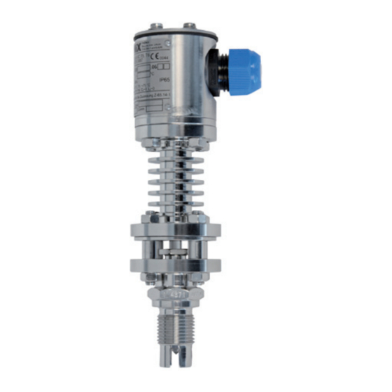
Transducer model LSO.06 and
switching amplifier model LSO.25
Messwandler Typ LSO.06 und
Schaltverstärker Typ LSO.25
Transducteur de mesure type LSO.06 et
relais amplificateur type LSO.25
Transductor modelo LSO.06 y
amplificador de conmutación modelo LSO.25
Switching amplifier
model LSO.25
Operating instructions
Betriebsanleitung
Mode d'emploi
Manual de instrucciones
Transducer
model LSO.06
GB
D
F
E
Kapitel

Verwandte Anleitungen für WIKA LSO.06


Inhaltszusammenfassung für WIKA LSO.06
- Seite 1 Manual de instrucciones Transducer model LSO.06 and switching amplifier model LSO.25 Messwandler Typ LSO.06 und Schaltverstärker Typ LSO.25 Transducteur de mesure type LSO.06 et relais amplificateur type LSO.25 Transductor modelo LSO.06 y amplificador de conmutación modelo LSO.25 Switching amplifier Transducer model LSO.25...
- Seite 35 Sicherheit Technische Daten Aufbau und Funktion Transport, Verpackung und Lagerung Inbetriebnahme, Betrieb Konfiguration Hinweise zu Montage und Betrieb im explosions- gefährdeten Bereich Wartung, Instandsetzung und Reinigung 10. Störungen 11. Garantie 12. Demontage, Rücksendung und Entsorgung WIKA Betriebsanleitung Typen LSO.06, LSO.25...
-
Seite 36: Allgemeines
Verletzungen führen kann, wenn sie nicht gemieden wird. VORSICHT! … weist auf eine möglicherweise gefährliche Situation hin, die zu gering- fügigen oder leichten Verletzungen bzw. Sach- und Umweltschäden führen kann, wenn sie nicht gemieden wird. WIKA Betriebsanleitung Typen LSO.06, LSO.25... -
Seite 37: Sicherheit
Kapiteln dieser Betriebsanleitung. 2.1 Bestimmungsgemäße Verwendung Der Messwandler Typ LSO.06 dient zur Grenzstanderfassung von Flüssigkeiten. Der Schaltverstärker Typ LSO.25 kann zusammen mit dem Messwandler Typ LSO.06 als Überfüllsicherung eingesetzt werden. Die Geräte sind sehr robust und für raue Industrie- umgebung ausgelegt. -
Seite 38: Personalqualifikation
Vorschriften zur Installation und Einsatz in explosionsgefährdeten Bereichen (z. B. IEC 60079-14, NEC, CEC) einhalten. Bei Nichtbeachten können schwere Körperverletzungen und/oder Sachschäden auftreten. Weitere wichtige Sicherheitshinweise für Geräte mit ATEX-Zulassung siehe Kapitel „2.3 Zusätzliche Sicherheitshinweise für Geräte mit ATEX-Zulassung“. WIKA Betriebsanleitung Typen LSO.06, LSO.25... - Seite 39 Ausreichende Vorsichtsmaßnahmen ergreifen. Dieses Gerät nicht in Sicherheits- oder in Not-Aus-Einrichtungen benutzen. Fehlerhafte Anwendungen des Gerätes können zu Verletzungen führen. Am Gerät können im Fehlerfall aggressive Medien mit extremer Temperatur und unter hohem Druck oder Vakuum anliegen. WIKA Betriebsanleitung Typen LSO.06, LSO.25...
- Seite 40 2. Sicherheit 2.5 Beschilderung / Sicherheitskennzeichnungen Typenschild Messwandler Typ LSO.06 ■ Symbolerklärung siehe Seite 41 Herstellungsdatum Schaltverstärker Typ LSO.25 ■ 19"-Steckkarte Im Aufbaugehäuse Symbolerklärung siehe Seite 41 Herstellungsdatum WIKA Betriebsanleitung Typen LSO.06, LSO.25...
- Seite 41 Geräte mit dieser Kennzeichnung stimmen überein mit den zutreffenden europäischen Richtlinien. ATEX Europäische Explosionsschutz-Richtlinie (Atmosphère = AT, explosible = Ex) Geräte mit dieser Kennzeichnung stimmen überein mit den Anforderungen der europäischen Richtlinie 94/9/EG (ATEX) zum Explosionsschutz. WIKA Betriebsanleitung Typen LSO.06, LSO.25...
-
Seite 42: Technische Daten
T6: bis 60 °C, T5: bis 75 °C ZELM 10 ATEX 0440 Elektrische Daten Kabelverschraubung M20 x 1,5, Ex: blau Klemmenanschluss 3 x 2,5 mm² Schutzart IP 65 nach EN 60529 Weitere technische Daten siehe WIKA Datenblatt LM 31.10 und Bestellunterlagen. WIKA Betriebsanleitung Typen LSO.06, LSO.25... - Seite 43 3. Technische Daten P-T-Diagramm (Druck- / Temperatureinsatzgrenzen) für Montageanschluss G ½ A nach DIN 910 Hochtemperaturausführung Standardausführung Tieftemperaturausführung Betriebsdruck in bar Derating-Diagramm (Temperatureinsatzgrenzen) Hochtemperatur- ausführung Standardausführung Tieftemperaturausführung Umgebungstemperatur in °C WIKA Betriebsanleitung Typen LSO.06, LSO.25...
- Seite 44 2,5 mm² Kabellänge 175 ... 600 m (0,5 ... 1,5 mm²) Schutzart 19"-Steckkarte IP 20 nach EN 60529 ■ Aufbaugehäuse IP 65 nach EN 60529 ■ Weitere technische Daten siehe WIKA Datenblatt LM 31.20 und Bestellunterlagen. WIKA Betriebsanleitung Typen LSO.06, LSO.25...
-
Seite 45: Aufbau Und Funktion
Normaldruckausführung Kühlrippenteil Kühlrippenteil Gewinde- Gewinde- ohne Kühlrippenteil anschluss NPT ½ anschluss G ½ A Gewindeanschluss Betriebsdruck in bar Betriebsdruck in bar Alle Messwandler-Typen benötigen einen Schaltverstärker Typ LSO.25 zur Auswertung und Signalgabe. WIKA Betriebsanleitung Typen LSO.06, LSO.25... -
Seite 46: Geräteaufbau
Ausführung von 50 bis 960 mm, Verlängerungsrohr/Schutzrohr wird in Fühler eingeschraubt Vorzugsmesslängen: 50, 60, 80, 90, 100, 120, 150, 200, 300, 600 und 800 mm Zwischenwerte sind über längenvariable Typen lieferbar *) 20 bei Hochdrucksensor WIKA Betriebsanleitung Typen LSO.06, LSO.25... - Seite 47 Dichtfläche. Bei Ex-Geräten in alternativ der Regel mit dem Fühlerteil dicht- dichtgeschweißt Dichtschweißung verschweißt (in diesem Falle ist der 6-kant nicht vorhanden). Einbaulänge EL = ML - Flanschdicke EL ab Dichtfläche Flansch ML ab Dichtfläche Fühler WIKA Betriebsanleitung Typen LSO.06, LSO.25...
- Seite 48 Trennschichtmessung mit U-Spitze, Verlängerungsrohr/Schutzrohr, Messlänge ML 50 ... 960 mm Trennschichtmessung mit U-Spitze, feste Messlänge ML 25 mm, ohne Verlängerungsrohr 4.2.2 Schaltverstärker Typ LSO.25 19"-Steckkarte ■ time delay on time delay off time delay Störung Signal Sicherung WIKA Betriebsanleitung Typen LSO.06, LSO.25...
-
Seite 49: Versorgungsspannungs-Codierleiste Rack Ausführung
A, C-D-E-F-G-H-J AC 24 V A-B, D-E-F-G-H-J DC 24 V A-B-C, E-F-G-H-J Codierleiste Steckkarte Codierleiste Rack Beispiel: AC 230 V Versorgungsspannungsversion Zur Sicherstellung der Anforderungen empfiehlt sich ausschließlich die Verwendung von geeigneten Baugruppenträgern von WIKA. WIKA Betriebsanleitung Typen LSO.06, LSO.25... -
Seite 50: Lieferumfang
Buchsenleiste eingesetzt. Auf der Gegenseite an der entsprechenden Stelle in der Messerleiste befindet sich eine Bohrung Im Aufbaugehäuse ■ time delay on time delay off time delay Störung Signal Sicherung Supply 75 hoch 4.3 Lieferumfang Lieferumfang mit dem Lieferschein abgleichen. WIKA Betriebsanleitung Typen LSO.06, LSO.25... -
Seite 51: Transport, Verpackung Und Lagerung
3. Bei längerer Einlagerung (mehr als 30 Tage) einen Beutel mit Trocknungsmittel der Verpackung beilegen. WARNUNG! Vor der Einlagerung des Gerätes (nach Betrieb) alle anhaftenden Messstoff- reste entfernen. Dies ist besonders wichtig, wenn der Messstoff gesund- heitsgefährdend ist, wie z. B. ätzend, giftig, krebserregend, radioaktiv, usw. WIKA Betriebsanleitung Typen LSO.06, LSO.25... -
Seite 52: Inbetriebnahme, Betrieb
Bei Überfüllsicherungen: in der Regel senkrecht von oben ■ Senkrechter Einbau ■ Einbau Typ LSO.06 senkrecht von oben in Behälter über Flanschanschluss z. B als Überfüllsicherung. Einbaulänge EL ab Dichtfläche Flansch ■ DIN-Flansche ab DN25 PN6 ■... -
Seite 53: Mechanische Montage
Pumpe, etwas versetzt aus der Mitte versehen mit Sieb um unempfindlicher gegenüber Gasblasen zu sein. Die Messlänge ML ist beim hier verwende- ten Typ LSO.06 mit 25 mm fest vorgegeben. 6.2 Mechanische Montage 6.2.1 Messwandler Typ LSO.06 VORSICHT! Arbeiten erst nach vollständigem Druckausgleich durchführen. -
Seite 54: Schaltverstärker Typ Lso.25 (Im Makrolongehäuse)
Bei dem elektrischen Anschluss alle zutreffenden Vorschriften einhalten. Die Messwandleranschlüsse sind sowohl am Messwandler als auch am Schaltverstärker gekennzeichnet mit den Farben WS (weiß) bzw. 2d, BR (braun) bzw. 4d und GN (grün) bzw. 6d, und entsprechend dem Anschlussplan zu verbinden. WIKA Betriebsanleitung Typen LSO.06, LSO.25... - Seite 55 Erde kann angeschlossen werden Bei Ex-Ausführung muss vom Schaltverstärker zum Messwandler ein hellblaues bzw. hellblau gekennzeichnetes Kabel installiert werden (eigensicherer Stromkreis). Der Schaltverstärker befindet sich im Nicht-Ex- Bereich und der Messkörper des Messwandlers in Zone 1. WIKA Betriebsanleitung Typen LSO.06, LSO.25...
- Seite 56 Erde kann an der internen Erdungsschraube aufgelegt werden (ist für Eigensicherheit nicht unbedingt notwendig) oder die Kontaktierung erfolgt über den metallischen Kontakt des Einschraubgewindes mit dem Behälter. 6.3.2 Schaltverstärker Typ LSO.25 19"-Steckkarte Aufbaugehäuse Federleiste nach DIN 41612 Schraubklemmen Federleisten-Anschlussseite Reihe WIKA Betriebsanleitung Typen LSO.06, LSO.25...
-
Seite 57: Anschluss Netzversorgung
LED, solange die Test-Taste gedrückt bleibt. Dies zeigt an, dass Verdrahtung und Schaltverstärker in Ordnung sind. Sollte dies nicht der Fall sein, erst die Justageanleitung siehe Kapitel „7.2 Justage mit CAL“ beachten. Bei eventuell auftretenden Störungen Maßnahmen siehe Kapitel „10. Störungen“ beachten. WIKA Betriebsanleitung Typen LSO.06, LSO.25... -
Seite 58: Konfiguration
Medium geschlossen dauernd ein angezogen Tiefalarm offen dauernd ein angezogen Trocken Fühler im optisch Hochalarm dünneren Medium geschlossen blinkt abgefallen Tiefalarm time delay on time delay off time delay Störung Signal Sicherung Supply 75 hoch WIKA Betriebsanleitung Typen LSO.06, LSO.25... -
Seite 59: Justage Mit Cal
6) diesen Wert im eingetauchten Zustand einstellen. Durch Variation in dem angegebenen Bereich kann die Schalteigenschaft des Systems Messwertgeber/Schaltverstärker beeinflusst werden: Um eine stabile Messung zu bekommen, sollte versucht werden, einen möglichst großen Unterschied zwischen dem Benetzt- und dem Trockenwert einzustellen. WIKA Betriebsanleitung Typen LSO.06, LSO.25... -
Seite 60: Einstellen Der Verzögerung
S1 offen S1 zu S1 offen S1 zu Glasspitze Messwandler trocken S1 offen S1 zu Legende: LED aus BEN = Benetzt LED blinkt TRO = Trocken LED dauernd an = mit P1 und P2 eingestellte Verzögerungszeit WIKA Betriebsanleitung Typen LSO.06, LSO.25... -
Seite 61: Verhalten Relais Störung
Interne Versorgungsspannungen für den eigensicheren Stromkreis bricht zusammen ■ Kurzschluss (BR-WS) oder Unterbrechung zur Infrarot-LED (BR) ■ Kurzschluss (GN-WS) oder Unterbrechung zum Fototransistor (GN) ■ Verhalten der LED-Anzeige siehe Tabelle „Störungsauswirkung zu Trocken/Benetzt“, Seite 58 WIKA Betriebsanleitung Typen LSO.06, LSO.25... -
Seite 62: Hinweise Zu Montage Und Betrieb Im Explosions- Gefährdeten Bereich
8. Hinweise zu Montage und Betrieb im explosionsgefähr- deten Bereich Zone 0 für Messwandler Typ LSO.06 Bestehen medienberührte Teile aus Titan, hat der Betreiber dafür zu sorgen, dass keine metallischen Einbauten im Behälter an die Sensorteile schlagen können und somit einen Schlagfunken auslösen könnten. -
Seite 63: Versorgungsspannung
Mitarbeiter und Umwelt vor Gefährdung durch anhaftende Messstoffreste zu schützen. Messstoffreste in ausgebauten Geräten können zur Gefährdung von ■ Personen, Umwelt und Einrichtung führen. Ausreichende Vorsichtsmaßnahmen sind zu ergreifen. Hinweise zur Rücksendung des Gerätes siehe Kapitel „12.2 Rücksendung“. WIKA Betriebsanleitung Typen LSO.06, LSO.25... -
Seite 64: Störungen
Können Störungen mit Hilfe der oben aufgeführten Maßnahmen nicht besei- tigt werden, ist das Gerät unverzüglich außer Betrieb zu setzen, sicherzu- stellen, dass kein Druck bzw. Signal mehr anliegt und gegen versehentliche Inbetriebnahme zu schützen. In diesem Falle Kontakt mit dem Hersteller aufnehmen. WIKA Betriebsanleitung Typen LSO.06, LSO.25... -
Seite 65: Garantie
Beim Ausbau besteht Gefahr durch austretende, gefährlich heiße Messstoffe. Diese Geräte nur im drucklosen Zustand demontieren! 12.2 Rücksendung WARNUNG! Beim Versand des Gerätes unbedingt beachten: Alle an WIKA gelieferten Geräte müssen frei von Gefahrstoffen (Säuren, Laugen, Lösungen, etc.) sein. WIKA Betriebsanleitung Typen LSO.06, LSO.25... - Seite 66 Dem Gerät das Rücksendeformular ausgefüllt beifügen. Das Rücksendeformular steht im Internet zur Verfügung: www.wika.de / Service / Rücksendung 12.3 Entsorgung Durch falsche Entsorgung können Gefahren für die Umwelt entstehen. Gerätekomponenten und Verpackungsmaterialien entsprechend den landesspezifischen Abfallbehandlungs- und Entsorgungsvorschriften umweltgerecht entsorgen. WIKA Betriebsanleitung Typen LSO.06, LSO.25...