WIKA IS-3 Betriebsanleitung
Druckmessumformer

Verwandte Anleitungen für WIKA IS-3


Inhaltszusammenfassung für WIKA IS-3
- Seite 1 Operating instructions Betriebsanleitung Pressure transmitter model IS-3 Druckmessumformer Typ IS-3 ® Pressure transmitters model IS-3...
- Seite 53 4. Aufbau und Funktion 5. Transport, Verpackung und Lagerung 6. Inbetriebnahme, Betrieb 7. Nullpunkt und Spanne justieren 8. Wartung und Reinigung 9. Störungen 10. Demontage, Rücksendung und Entsorgung Anlage 1: Konformitätserklärung Konformitätserklärungen finden Sie online unter www.wika.de. WIKA Betriebsanleitung Druckmessumformer, Typ IS-3...
-
Seite 54: Allgemeines
Es gelten die allgemeinen Geschäftsbedingungen in den Verkaufsunterlagen. ■ Technische Änderungen vorbehalten. ■ Weitere Informationen: ■ - Internet-Adresse: www.wika.de / www.wika.com - zugehöriges Datenblatt: PE 81.58 - Anwendungsberater: Tel.: +49 9372 132-8976 Fax: +49 9372 132-8008976 support-tronic@wika.de WIKA Betriebsanleitung Druckmessumformer, Typ IS-3... -
Seite 55: Symbolerklärung
… weist auf eine möglicherweise gefährliche Situation hin, die zu geringfügigen oder leichten Verlet- zungen bzw. Sach- und Umweltschäden führen kann, wenn sie nicht gemieden wird. Information … hebt nützliche Tipps und Empfehlungen sowie Informationen für einen effizienten und störungsfreien Betrieb hervor. WIKA Betriebsanleitung Druckmessumformer, Typ IS-3... -
Seite 56: Sicherheit
1/2 und 2 erfordern, verwendet. Zulassung ATEX und IECEx: Druckmessgerät zur bestimmungsgemäßen Verwendung in explosionsgefährdeten Bereichen. EG-Baumusterprüfbescheinigung: BVS 14 ATEX E 035 X Zertifikate IECEx: IECEx BVS 14.0030 X (Ex i), IECEx BVS 14.0109X (Ex nA und Ex tc) WIKA Betriebsanleitung Druckmessumformer, Typ IS-3... -
Seite 57: Personalqualifikation
Erfahrungen sowie Kenntnis der landesspezifischen Vorschriften, geltenden Normen und Richtlinien in der Lage, die beschriebenen Arbeiten auszuführen und mögliche Gefahren selbstständig zu erkennen. Spezielle Einsatzbedingungen verlangen weiteres entsprechendes Wissen, z. B. über aggressive Messstoffe. WIKA Betriebsanleitung Druckmessumformer, Typ IS-3... -
Seite 58: Besondere Gefahren
Dieses Gerät nicht in Sicherheits- oder in Not-Aus-Einrichtungen benutzen. Fehlerhafte Anwendungen des Gerätes können zu Verletzungen führen. Am Gerät können im Fehlerfall aggressive Messstoffe mit extremer Temperatur und unter hohem Druck oder Vakuum anliegen. Weitere wichtige Sicherheitshinweise befinden sich in den einzelnen Kapiteln dieser Betriebsanleitung. WIKA Betriebsanleitung Druckmessumformer, Typ IS-3... -
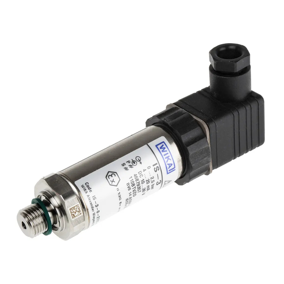
Seite 59: Beschilderung, Sicherheitskennzeichnungen
Typcode Code IS - 3 - X - XXXX- XXX - XXXXXXX - XXXXXXX - XXXX Codiertes Herstelldatum WIKA Alexander Wiegand SE & Co. KG, 63911 Klingenberg Made in Germany Symbolerklärung Vor Montage und Inbetriebnahme des Gerätes unbedingt die Betriebsanleitung lesen! CE, Communauté... - Seite 60 4 = IECEx + ATEX Zone 2 / 22 Zündschutzart 1 = Eigensicher 2 = nicht funkend nA 3 = nicht funkend nA + Staubexplosionsschutz durch Gehäuse tc Einstellbarkeit Z = ohne T = Nullpunkt / Spanne einstellbar WIKA Betriebsanleitung Druckmessumformer, Typ IS-3...
-
Seite 61: Technische Daten
E = -20 … +60 °C C = -20 … +150 °C 6 = -15 … +60 °C 7 = -15 … +70 °C 8 = -40 … +150 °C 9 = -40 … +200 °C WIKA Betriebsanleitung Druckmessumformer, Typ IS-3... - Seite 62 0 ... 0,6 0 ... 1 0 ... 1,6 0 ... 2,5 Überlast-Druckgrenze Messbereich 0 ... 4 0 ... 6 0 ... 10 0 ... 16 0 ... 25 Überlast-Druckgrenze 19,3 41,4 41,4 82,8 82,8 WIKA Betriebsanleitung Druckmessumformer, Typ IS-3...
-
Seite 63: Prozessanschlüsse Und Überlast-Druckgrenzen (Prozessanschluss Siehe Typcode)
1.000 1.500 SAE J514 E 7/16-20 UNF BOSS 9/16-18 UNF BOSS DIN 16288 M20 x 1,5 1.000 1.800 ISO 7 R ¼ 1.000 1.600 R ⅜ 1.000 1.400 JIS B7505-76 G ¼ B 1.000 1.000 WIKA Betriebsanleitung Druckmessumformer, Typ IS-3... -
Seite 64: Prozessanschlüsse Für Die Optionalen Messstofftemperaturen
ANSI/ASME B1.20.1 ½ NPT ISO 7 R ¼ G ½ B frontbündig G 1 B frontbündig G 1 B frontbündig, Hygienic 1) Einschränkungen abhängig vom Dichtwerkstoff, siehe Tabelle „Einschränkungen der Dichtwerkstoffe für Prozessanschluss G½ B frontbündig“ WIKA Betriebsanleitung Druckmessumformer, Typ IS-3... - Seite 65 T= 80 °C T= 100 °C T= 120 °C T= 150 °C 1.200 1.200 1.200 FKM/FPM (Viton 1.200 1.200 1.200 ® FFKM 1.200 1.200 1.200 1.200 1.200 EPDM 1.200 T= Messstofftemperatur N/A = nicht möglich WIKA Betriebsanleitung Druckmessumformer, Typ IS-3...
-
Seite 66: Ausgangssignal
Analogsignal 4 ... 20 mA Zulässige Bürde in Ω Typ IS-3: ≤ (Hilfsenergie - 10 V) / 0,02 A - (Kabellänge in m x 0,14 Ω) ■ Typ IS-3 mit Feldgehäuse: ≤ (Hilfsenergie - 11 V) / 0,02 A ■... - Seite 67 II 3D Ex tc IIIC T90 °C Dc X ■ II 1D Ex ia IIIC T135 °C Da ■ II 1/2D Ex ia IIIC T135 °C Da/Db ■ I M1 Ex ia I Ma ■ WIKA Betriebsanleitung Druckmessumformer, Typ IS-3...
- Seite 68 3) Voraussetzung: Vermeidung von Wasseransammlung in Schutzkappe Vibrationsfestigkeit Typ IS-3: 20 g ■ (nach IEC 60068-2-6, Vibration Typ IS-3 mit Feldgehäuse und Kabelausgang IP 67 mit Schutzkappe: 10 g ■ bei Resonanz) Messbereich > 1.000 bar und optionale Messstofftemperaturbereiche: 5 g ■...
- Seite 69 - Kabelausgang IP 68 (dauerhafter Einsatz im Medium), FEP Kabel: -15 ... +80°C Lagerung: -20 ... +80 °C ■ Zulässige Temperaturen für den Betrieb gemäß Datenblattspezifikation (für Zündschutzart Ex nA und Ex tc) Messstoff: -15 ... +70 °C (für Sauerstoff -15 ... +60 °C) ■ Umgebung: -15 ... +70 °C ■ Lagerung: -15 ... +70 °C ■ WIKA Betriebsanleitung Druckmessumformer, Typ IS-3...
- Seite 70 Nicht einstellbar -30 ≤ T ≤ +105 IS-3-*-****-***-*******-*ZM2Z**-**** 1/2D Da/Db IIIC -30 ≤ T ≤ +40 (750 mW) 135 °C -30 ≤ T ≤ +70 (650 mW) Einstellbar -30 ≤ T ≤ +100 (550 mW) IS-3-*-****-***-*******-*TM2Z**-**** WIKA Betriebsanleitung Druckmessumformer, Typ IS-3...
- Seite 71 ≤ +70 Nicht einstellbar -30 ≤ T ≤ +70 IS-3-*-****-***-*******-*Z5WA**-**** IIIC -30 ≤ T ≤ +40 (750 mW) 135 °C 1/2D Da/Db -30 ≤ T ≤ +70 (650 mW) -30 ≤ T ≤ +70 (550 mW) WIKA Betriebsanleitung Druckmessumformer, Typ IS-3...
- Seite 72 ≤ +40 (750 mW) 135 °C 1/2D Da/Db IIIC -50 ≤ T Feldgehäuse -50 ≤ T ≤ +70 (650 mW) Kabelverschraubung CrNi-Stahl -50 ≤ T ≤ +100 (550 mW) IS-3-*-****-***-*******-*TFCZ**-**** IS-3-*-****-***-*******-*TFDZ**-**** Feldgehäuse, Conduit IS-3-*-****-***-*******-*TFSZ**-**** IS-3-*-****-***-*******-*TFTZ**-**** IS-3-*-****-***-*******-*TFLZ**-**** IS-3-*-****-***-*******-*TFMZ**-**** WIKA Betriebsanleitung Druckmessumformer, Typ IS-3...
- Seite 73 ≤ +70 (650 mW) -20 ≤ T ≤ +85 (550 mW) Wird von WIKA ein zugehöriger Gegenstecker bezogen, reduziert sich der Umgebungs- bzw. Messstofftemperaturbe- reich für folgende Varianten des elektrischen Anschlusses: Rundsteckverbinder M12 x 1: -20 ... +80 °C Winkelstecker gem. DIN EN 175301-803 A Bestell-Nr.
- Seite 74 Max. Messstofftemperatur (°C) Max. Umgebungstemperatur (°C) Kabelausgang IP 68, FEP (dauerhafter Einsatz im Medium) IS-3-*-****-***-*******-*ZDCB**-**** Rundsteckverbinder M16 x 0,75 IS-3-*-****-***-*******-*TB4Z**-**** IS-3-*-****-***-*******-*ZB4Z**-**** Feldgehäuse Kabelverschraubung Kunststoff IS-3-*-****-***-*******-*TFAZ**-**** IS-3-*-****-***-*******-*TFBZ**-**** Rundsteckverbinder 7/8-16 UN IS-3-*-****-***-*******-*ZM6Z**-**** Kabelausgänge PUR IS-3-*-****-***-*******-*TDPA**-**** IS-3-*-****-***-*******-*ZXPA**-**** IS-3-*-****-***-*******-*TXPA**-**** IS-3-*-****-***-*******-*Z5WA**-**** IS-3-*-****-***-*******-*ZDCA**-**** WIKA Betriebsanleitung Druckmessumformer, Typ IS-3...
- Seite 75 Kabelverschraubung CrNi-Stahl IS-3-*-****-***-*******-*TFCZ**-**** IS-3-*-****-***-*******-*TFDZ**-**** Feldgehäuse Conduit IS-3-*-****-***-*******-*TFSZ**-**** IS-3-*-****-***-*******-*TFTZ**-**** IS-3-*-****-***-*******-*TFLZ**-**** IS-3-*-****-***-*******-*TFMZ**-**** Wird von WIKA ein zugehöriger Gegenstecker bezogen, reduziert sich die max. Umgebungstemperatur für folgende Varianten des elektrischen Anschlusses: Rundsteckverbinder M12 x 1: -20 ... +80 °C WIKA Betriebsanleitung Druckmessumformer, Typ IS-3...
- Seite 76 Max. Messstofftemperatur (°C) Max. Umgebungstemperatur (°C) Kabelausgang IP 68, FEP (dauerhafter Einsatz im Medium) IS-3-*-****-***-*******-*ZDCB**-**** Rundsteckverbinder M16 x 0,75 IS-3-*-****-***-*******-*TB4Z**-**** IS-3-*-****-***-*******-*ZB4Z**-**** Feldgehäuse Kabelverschraubung Kunststoff IS-3-*-****-***-*******-*TFAZ**-**** IS-3-*-****-***-*******-*TFBZ**-**** Rundsteckverbinder 7/8-16 UN IS-3-*-****-***-*******-*ZM6Z**-**** Kabelausgänge PUR IS-3-*-****-***-*******-*TDPA**-**** IS-3-*-****-***-*******-*ZXPA**-**** IS-3-*-****-***-*******-*TXPA**-**** IS-3-*-****-***-*******-*Z5WA**-**** IS-3-*-****-***-*******-*ZDCA**-**** WIKA Betriebsanleitung Druckmessumformer, Typ IS-3...
- Seite 77 Kabelverschraubung CrNi-Stahl IS-3-*-****-***-*******-*TFCZ**-**** IS-3-*-****-***-*******-*TFDZ**-**** Feldgehäuse Conduit IS-3-*-****-***-*******-*TFSZ**-**** IS-3-*-****-***-*******-*TFTZ**-**** IS-3-*-****-***-*******-*TFLZ**-**** IS-3-*-****-***-*******-*TFMZ**-**** Wird von WIKA ein zugehöriger Gegenstecker bezogen, reduziert sich die max. Umgebungstemperatur für folgende Varianten des elektrischen Anschlusses: Rundsteckverbinder M12 x 1: -20 ... +80 °C WIKA Betriebsanleitung Druckmessumformer, Typ IS-3...
- Seite 78 Kabelausgang IP 68 (dauerhafter Einsatz im Medium) Nicht einstellbar IS-3-*-****-***-*******-*ZDCA**-**** Kabelausgang IP 68 (dauerhafter Einsatz im Medium) -15 ≤ Ta ≤ +70 IIIC T90 °C Nicht einstellbar IS-3-*-****-***-*******-*ZDCB**-**** Kabelausgang IP 67 mit Schutzkappe Nicht einstellbar IS-3-*-****-***-*******-*ZDOA**-**** WIKA Betriebsanleitung Druckmessumformer, Typ IS-3...
- Seite 79 ■ Kabelausgang IP 68: CrNi-Stahl ■ Feldgehäuse: CrNi-Stahl, Messing vernickelt / CrNi-Stahl / PA ■ Internes Übertragungsmedium ■ - Keine Sauerstoffausführung: Synthetisches Öl - Sauerstoffausführung: Halocarbonöl - Geräte mit Messbereich > 25 bar: Trockene Messzelle WIKA Betriebsanleitung Druckmessumformer, Typ IS-3...
-
Seite 80: Ce-Konformität
SIL 2, Funktionale Sicherheit ■ 3-A, Lebensmittel, USA ■ GL, Schiffe, Schiffbau (z. B. Offshore), Deutschland ■ 1) siehe “Ergänzung der Betriebsanleitung/Sicherheitstechnische Daten” für IS-3 auf www.wika.de Weitere technische Daten siehe WIKA-Datenblatt PE 81.58 und Bestellunterlagen. WIKA Betriebsanleitung Druckmessumformer, Typ IS-3... -
Seite 81: Aufbau Und Funktion
Verpackung erst unmittelbar vor der Montage entfernen. Die Verpackung aufbewahren, denn diese bietet bei einem Transport einen optimalen Schutz (z. B. wechselnder Einbauort, Reparatursendung). 5.3 Lagerung Die Schutzkappe vor der Einlagerung des Gerätes montieren, um den Prozessanschluss vor Beschädigungen zu schützen. WIKA Betriebsanleitung Druckmessumformer, Typ IS-3... -
Seite 82: Inbetriebnahme, Betrieb
6. Inbetriebnahme, Betrieb 6.1 Montagehinweise WARNUNG! Vor Montage, Inbetriebnahme und Betrieb sicherstellen, dass das richtige Gerät hinsichtlich Messbereich, Ausführung und spezifischen Messbedingungen ausgewählt wurde. Bei Nichtbeachten können schwere Körperverletzungen und/oder Sachschäden auftreten. WIKA Betriebsanleitung Druckmessumformer, Typ IS-3... - Seite 83 Betrieb bei Messstofftemperaturen ≤ 105 °C (für Zündschutzart Ex i)“ festgelegten Temperaturbereichs nicht überschreiten. Bei Druckmessumformern mit frontbündigem Prozessanschluss und Kühlstrecke darf die Temperatur am Gehäuse oberhalb der Kühlrippen nicht größer als der Tabellenwert sein. WIKA Betriebsanleitung Druckmessumformer, Typ IS-3...
-
Seite 84: Besondere Bedingungen Für Die Sichere Anwendung Im Ex-Bereich (Für Zündschutzart Ex I)
Anschlüsse für den sicheren Betrieb bei Messstofftemperaturen ≤ 105 °C (für Zündschutzart Ex i)“ beschriebenen Messstofftemperaturbereichen ist mit speziellen Kühlstrecken zulässig. Es dürfen jedoch nicht die zulässigen Oberflächentemperaturen überschritten werden, die für diesen Bereich auf Grund der festgelegten Temperaturklassen gelten. WIKA Betriebsanleitung Druckmessumformer, Typ IS-3... -
Seite 85: Besondere Bedingungen Für Die Sichere Anwendung Im Ex-Bereich (Für Zündschutzart Ex Na Und Ex Tc)
Bauteile zum Einsatz kommen, die für die höchsten zu erwartenden Druck- spitzen ausgelegt sind. Sicherstellen, dass die Montagestelle absolut gratfrei gearbeitet und sauber ist. ■ Bei Drücken > 1.000 bar einen passenden Druckring verwenden. ■ WIKA Betriebsanleitung Druckmessumformer, Typ IS-3... - Seite 86 Zur Abdichtung sind an der Dichtfläche Flach- dichtungen, Dichtlinsen oder WIKA-Profildichtungen einzusetzen. nach EN 837 nach DIN 3852-E Kegelige Gewinde Zur Abdichtung wird das Gewinde, mit zusätzlichen Dichtwerkstoffen, z. B. PTFE-Band umwickelt. NPT, R und PT WIKA Betriebsanleitung Druckmessumformer, Typ IS-3...
- Seite 87 (Form/Werkstoff). Das maximale Drehmoment beträgt 50 Nm. Den vorgeschriebenen Anzugsdrehmoment der Hochdruckrohre einhalten (siehe Angabe des Rohrlieferanten). Bei nichtbeachtung kann das Gerät oder die Messstelle beschädigt werden. Schlüsselfläche Angaben zu Einschraublöchern und Einschweißstutzen siehe Technische Information IN 00.14 unter www.wika.de WIKA Betriebsanleitung Druckmessumformer, Typ IS-3...
-
Seite 88: Elektrische Montage
(siehe EN 60079-14 Abschnitt 5.4). Für Zündschutzart Ex nA und Ex tc ■ Den Druckmessumformer mit Kennzeichnung „Ex nA IIC T4/T5/T6“ an einen Versorgungs- und Signalstromkreis mit Schutz vor Transienten gemäß IEC 60079-15:2010 Abschnitt 13 c) anschließen. WIKA Betriebsanleitung Druckmessumformer, Typ IS-3... - Seite 89 1,5 mm² Kabeldurchmesser 6 ... 8 mm Schiffszulassung: 10 ... 14 mm Schutzart nach IEC 60529 IP 65 IP 67 IP 67 IP 67 Die angegebenen Schutzarten gelten nur im gesteckten Zustand mit Gegensteckern entsprechender Schutzart. WIKA Betriebsanleitung Druckmessumformer, Typ IS-3...
- Seite 90 übereinstimmen. Eine minimale Schutzart von IP 54 gemäß IEC 60529 muss sichergestellt werden. Benötigter Anzugsmoment für Gegenstecker: 1 Nm für M16 x 0.75 gem. IEC 61076-2-106 ■ Die angegebenen Schutzarten gelten nur im gesteckten Zustand mit Gegensteckern entsprechender Schutzart. WIKA Betriebsanleitung Druckmessumformer, Typ IS-3...
- Seite 91 Kabelverschraubung CrNi-Stahl: 8...15 mm Kabelverschraubung Kunststoff: 6,5...12 mm Schutzart nach IEC 60529 IP 67 (Voraussetzung: IP 69K Vermeidung von Wasseran- sammlung in Schutzkappe) Die angegebenen Schutzarten gelten nur im gesteckten Zustand mit Gegensteckern entsprechender Schutzart. WIKA Betriebsanleitung Druckmessumformer, Typ IS-3...
- Seite 92 Klemmkontakt zu öffnen. Das konfektionierte Kabelende in die Öffnung stecken und den Kunststoffhebel loslassen. Das Kabelende ist nun im Federklemmblock befestigt. 4. Nach Anschließen der einzelnen Adern, die Kabelverschraubung festziehen und den Gehäusedeckel verschrauben. Gehäusedeckel Kabelverschraubung Federklemmblock WIKA Betriebsanleitung Druckmessumformer, Typ IS-3...
- Seite 93 9. Die quadratische Flachdichtung über die Anschlusspins des Druckmessum- formers legen. 10. Den Klemmblock (6) auf die Anschlusspins des Druckmessumformers schieben. 11. Mit der Schraube (1) das Winkelgehäuse (5) mit dem Klemmblock (6) am Druckmessumformer verschrauben. WIKA Betriebsanleitung Druckmessumformer, Typ IS-3...
-
Seite 94: Funktionsprüfung
1. Den elektrischen Anschluss (1) vom Gerät trennen. 2. Den Griffring (2) lösen. 3. Den Gerätestecker (3) vorsichtig aus dem Gerät ziehen. Schraube, Feldgehäuse (Abbildung A) Die Schraube auf der Gehäuseoberseite bzw. den Gehäusedeckel abschrauben. WIKA Betriebsanleitung Druckmessumformer, Typ IS-3... -
Seite 95: Feldgehäuse
2. Das Messbereichsende anfahren. 3. Über das Potentiometer „S“ das maximale Ausgangssignal justieren (z. B. 20 mA). 4. Den Nullpunkt überprüfen und bei Abweichung erneut justieren. 5. Den Vorgang solange wiederholen bis Nullpunkt und Spanne korrekt eingestellt sind. WIKA Betriebsanleitung Druckmessumformer, Typ IS-3... -
Seite 96: Justage Abschließen (Abbildung A)
Schraube, Feldgehäuse (Abbildung A) Die Schraube bzw. den Gehäusedeckel wieder einschrauben. Nach dem Justieren die korrekte Arbeitsweise des Systems überprüfen. Empfohlener Nachkalibrierzyklus: jährlich (siehe Kapitel 8.3 „Rekalibrierung“) Bei Fragen den Hersteller kontaktieren, siehe Anwendungsberater unter Kapitel 1 „Allgemeines“ WIKA Betriebsanleitung Druckmessumformer, Typ IS-3... -
Seite 97: Wartung Und Reinigung
Hinweise zur Rücksendung des Gerätes siehe Kapitel 10.2 „Rücksendung“. 8.3 Rekalibrierung Es wird empfohlen, das Gerät in regelmäßigen Zeitabständen von ca. 12 Monaten durch den Hersteller rekalibrieren zu lassen. Die Grundeinstellungen werden wenn notwendig korrigiert. WIKA Betriebsanleitung Druckmessumformer, Typ IS-3... -
Seite 98: Störungen
Am Gerät können im Fehlerfall aggressive Messstoffe mit extremer Temperatur und unter hohem Druck oder Vakuum anliegen. Bei diesen Messstoffen müssen über die gesamten allgemeinen Regeln hinaus die einschlägigen ■ Vorschriften beachtet werden. Notwendige Schutzausrüstung tragen. ■ WIKA Betriebsanleitung Druckmessumformer, Typ IS-3... - Seite 99 Betrieb zu setzen, sicherzustellen, dass kein Druck bzw. Signal mehr anliegt und gegen versehentliche Inbetriebnahme zu schützen. In diesem Falle Kontakt mit dem Hersteller aufnehmen. Bei notwendiger Rücksendung die Hinweise unter Kapitel 10.2 „Rücksendung“ beachten. WIKA Betriebsanleitung Druckmessumformer, Typ IS-3...
-
Seite 100: Demontage, Rücksendung Und Entsorgung
Eine Schutzvorrichtung anbringen, die das Herausschleudern von Teilen verhindert. Die Schutz- ■ vorrichtung darf nicht ohne Werkzeug entfernbar sein. 3. Den Druckmessumformer von Messstoffresten befreien (siehe Kapitel 8.2 „Reinigung“) 4. Den Druckmessumformer einpacken (siehe Kapitel 5.2 „Verpackung“) WIKA Betriebsanleitung Druckmessumformer, Typ IS-3... -
Seite 101: Rücksendung
10.2 Rücksendung WARNUNG! Beim Versand des Gerätes unbedingt beachten: Alle an WIKA gelieferten Geräte müssen frei von Gefahrstoffen (Säuren, Laugen, Lösungen, etc.) sein. Zur Rücksendung des Gerätes die Originalverpackung oder eine geeignete Transportverpackung verwenden. Um Schäden zu vermeiden: 1. Das Gerät in eine antistatische Plastikfolie einhüllen. -
Seite 102: Anlage 1: Konformitätserklärung
Anlage 1: Konformitätserklärung WIKA Betriebsanleitung Druckmessumformer, Typ IS-3... - Seite 104 WIKA subsidiaries worldwide can be found online at www.wika.com. WIKA Niederlassungen weltweit finden Sie online unter www.wika.de. WIKA Alexander Wiegand SE & Co. KG Alexander-Wiegand-Straße 30 63911 Klingenberg • Germany Tel. +49 9372 132-0 Fax +49 9372 132-406 info@wika.de www.wika.de...