Herunterladen Inhalt Inhalt Diese Seite drucken
bürkert 0911 Bedienungsanleitung
Vorschau ausblenden Andere Handbücher für 0911:
Inhaltsverzeichnis

Werbung

Verfügbare Sprachen

Verfügbare Sprachen

Operating Instructions
Bedienungsanleitung
Instructions de Service
Type 091 1
3-stage controller
3-Punkt-Regler
3 Régulateur ponctuel
Id. No. 788 271
788 272
788 273
788 274

Werbung

Inhaltsverzeichnis
loading

Inhaltszusammenfassung für bürkert 0911

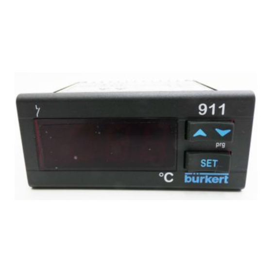
  • Seite 1 Operating Instructions Bedienungsanleitung Instructions de Service Type 091 1 3-stage controller 3-Punkt-Regler 3 Régulateur ponctuel Id. No. 788 271 788 272 788 273 788 274...
  • Seite 2 We reserve the right to make technical changes without notice. Technische Änderungen vorbehalten. Sous resérve de modification techniques. © 2004 Bürkert Werke GmbH & Co. KG Operating Instructions 0207/05_EU-ml_00804598...
  • Seite 3: Inhaltsverzeichnis

    ASSEMBLY, INSTALLATION AND COMMISSIONING ............General information regarding the installation and operation ......... Assembly ..............................Electrical connections .......................... HOT-KEY FUNCTION ..........................FACTORY SETTINGS ..........................MAINTENANCE ............................REPAIR WORK .............................. Faults ................................Ordering table for basic unit/accessories ................0911 - 1...
  • Seite 4: General Information

    Please observe the notes in these operating instructions together with the conditions of use and permitted data that are specified in the data sheets of the 0911 controller, so that the device will function perfectly and will have a long service life.
  • Seite 5: Scope Of Delivery

    Scope of delivery Immediately after receiving the delivery, ensure that the contents agree with the scope of the delivery. This includes: • 1 Type 0911 controller • 1 set of operating instructions (where required, on a data carrier) • 1 front seal •...
  • Seite 6: System Description

    5 = without units Operation down- wards LED1 LED 2 wards ES LED Output LEDs Alarm button BUTTONS SET1 Display of Set-value 1 Changing and confirming a default during the programming phase SET2 Display of Set-value 2 4 - 0911...
  • Seite 7: Button Combinations

    (only for parameter OnF = yes). DISPLAYING THE SET VALUE Briefly press the SET button once. The set-value display appears in the display. Briefly press the SET button again, or wait 5 seconds in order to display the room temperature. 0911 - 5...
  • Seite 8: Adding/Removing Parameters In The User Level Pr1

    ADDING/REMOVING PARAMETERS IN THE USER LEVEL PR1 Accessing the programming level The status can be changed with the SET1 + buttons. If a parameter is not visible in the PR1 level, this will be indicated by an LED point. 6 - 0911...
  • Seite 9: Locking And Unlocking The Keypad

    S = Thermoelement S; ntc = NTC Type AU (control devices with current/voltage input): cur = 4...20 mA; 0-1 = 0...1 V; 10 = 0...10 V Confirm the default with the SET button. Briefly switch off the power to the device. 0911 - 7...
  • Seite 10: Soft-Start Function

    Dynamic set-value increase (in °C or °F; deactivated with 0). This value determines the step-by-step increase of the set-value of SET1. Clock time for the dynamic set-value increase (1...999 sec) or dSl (SOFT-Start). Ta = Measured temperature after device commissioning. Time axis. 8 - 0911...
  • Seite 11: Proportional Control

    Evaluate (poss. using a plotter) the values Tp and dT (see diagram) Calculate the parameters Pb, Int, dEt, Cyt from these values - as follows: Pb = 2 x dT Int = Tp / 2 dEt = Tp / 8 Cyt = Tp / 20 0911 - 9...
  • Seite 12: Parameters

    The control function is predefined with S2C. Control type onF = ON/OFF db = not predefined! Pid = PID; tt = not predefined! Lowest set-value setting Set-value limits 1 for operator Lowest set-value setting Set-value limits 2 for operator 10 - 0911...
  • Seite 13 Suppression of alarms after mains ON (0...23.5 h) Commissioning Status of the control relay oFF = opened with sensor fault on = closed So2 S Status of the control relay oFF = opened with sensor fault on = closed 0911 - 11...
  • Seite 14 Current / voltage input cur = 4...20 mA; 0-1 = 0...1 V; (AU) 10 = 0...10 V Only for devices with an input of 4...20 mA or 0...1 V or 0...10 V Only for current or voltage input 12 - 0911...
  • Seite 15 4 sec. If you want to change the set- value, hold down the SET button for 2 sec. Number of the parameter- only read-out value table Version only read-out value Display of the parameters in Level Pr2 display only 0911 - 13...
  • Seite 16 (SOFT-Start). (1...999 sec) NOTE You can access hidden parameters by holding down the buttons SET + for 3 seconds in the programming level HY. The message Pr2 appears. 14 - 0911...
  • Seite 17: Controlling The Loads

    Parameter S1C = in; The value HY has been preset to 2 K in the factory. If the temperature falls below the value SET-HY, the controller output will be switched on and will be switched off again when SET is exceeded. 0911 - 15...
  • Seite 18: Technical Data

    -30 ... +85°C / -22 ... +185°F • Air humidity 20 ... 85% (non-condensing) • Measurement range according to sensor • Resolution 0.1°C or 1°F • Accuracy at + 25 °C better than 0.5% of the measurement range 16 - 0911...
  • Seite 19: Assembly, Installation And Commissioning

    In order to ensure the IP65 front protection, a rubber seal must be fitted begind the front frame (optional with RG-C). The ambient temperature for trouble-free operetion is in the range from 0 ... +60°C. Ensure sufficient ventilation through the cooling slots. Mounting bracket Panel 0911 - 17...
  • Seite 20: Electrical Connections

    . The device is provided with the corresponding screw terminals. Check the auxiliary power before connection the voltage supply (see Chapter Technical data ). Do not load the relay contacts higher than permitted. If necessary, use a contactor. 18 - 0911...
  • Seite 21: Pin Assignment

    230 V AC Standard signal input: 0...1 V; 0...10 V = 9(+), 11(-) 4...20 mA = 9(+), 11(-) Thermoelement J, K, S = 9(+) -11(-) sensor: Pt100 = 9 -11(10) voltage supply: 230 V AC = 7 - 8 0911 - 19...
  • Seite 22: Hot-Key Function

    The following messages are possible at the end of the data transfer: end for a correct data transfer err for a failed data transfer In this case, press the SET button again to repeat the procedure. If you want to cancel the procedure, remove the HOT-KEY. 20 - 0911...
  • Seite 23: Factory Settings

    (ALC = rE; ALC = Ab) range Upper Alarm Limit dependent on measurement (ALC = rE; ALC = Ab) range Switch hysterisis for dependent on measurement temperature alarms range Alarm delay time during 0...999 min the operation 0...23.5 h Parameter Programming level 0911 - 21...
  • Seite 24 Pt = Pt100; J = tcJ; c = tck; S = tcS; Ptc = PTC; Type of sensor var. ntc = NTC; 0.1 = 0...1 V; 10 = 0...10 V; cur = 0...20 mA Parameter Programming level Only for devices with voltage and current input 22 - 0911...
  • Seite 25: Maintenance

    0...120 min input Serial address for XJ500 RS485 address Activate Standby no = no; oFF = active function Parameter Programming level MAINTENANCE When operated in accordance with the instruction in this handbook, the 0911 controller is maintenance-free. 0911 - 23...
  • Seite 26: Repair Work

    Messages HA/LA - High/Low temperature alarm The messages disappear automatically as soon as the normal temperature range is reached again or if defrosting starts. • External alarms EAL and BAL are acknowledged after deactivation of the digital input. 24 - 0911...
  • Seite 27: Ordering Table For Basic Unit/Accessories

    3-stage controller 0911 4-20 mA; 0-10 V; 0-1 V 788 268 12-24 V AC/DC 3-stage controller 0911 230 V AC PTC/NTC; Pt100, Typ J, K, S 788 269 3-stage controller 0911 230 V AC 4-20 mA; 0-10 V; 0-1 V...
  • Seite 28 26 - 0911...
  • Seite 29 Regelung der Lasten ..........................TECHNISCHE DATEN ..........................MONTAGE, INSTALLATION UND INBETRIEBNAHME ..........Allgemeine Hinweise zu Installation und Betrieb ..............Montage ............................... Elektrische Anschlüsse ........................HOT-KEY FUNKTION ..........................WERKSEINSTELLUNG ......................... WARTUNG ..............................INSTANDHALTUNG ..........................Störungen ..............................Bestelltabelle Grundgerät/Zubehör ....................0911 - 27...
  • Seite 30: Allgemeine Hinweise

    Zusatzinformationen, Tipps und Empfehlungen. Sicherheitshinweise Bitte beachten Sie die Hinweise dieser Betriebsanleitung sowie die Einsatz- bedingungen und zulässigen Daten, die in dem Datenblatt des Reglers 0911 spezifiziert sind, damit das Gerät einwandfrei funktioniert und lange einsatzfä- hig bleibt. •...
  • Seite 31: Lieferumfang

    Haftung unsererseits, ebenso erlischt die Garantie auf Geräte und Zubehörteile! Lieferumfang Überzeugen Sie sich unmittelbar nach Erhalt der Lieferung, ob der Inhalt mit dem angegebenen Lieferumfang übereinstimmt. Zu diesem gehören: • 1 Regler Typ 0911 • 1 Betriebsanleitung (ggf. auf Datenträger) • 1 Frontdichtung •...
  • Seite 32: Systembeschreibung

    5 = ohne Maßeinheit Bedienung nach nach oben unten LED1 LED 2 ES LED Ausgangs LED´s SET- Alarm Tasten TASTEN SET1 Anzeige des Sollwertes 1 Ändern und Bestätigen einer Vorgabe während der Programmierphase SET2 Anzeige des Sollwertes 2 30 - 0911...
  • Seite 33: Gerät Ein-/Ausschalten

    (Nur bei Parameter OnF = yes). SOLLWERT ANZEIGEN Betätigen einmal kurz die SET-Taste. Die Sollwertan- zeige erscheint am Display. Betätigen Sie nochmals kurz die SET-Taste oder warten Sie 5 sec, um die Raumtemperatur anzeigen zu lassen. 0911 - 31...
  • Seite 34: Parameter In Anwenderebene Pr1 Hinzufügen / Entfernen

    SERVICE-EBENE PR2 (PASSWORT 321) Siehe: Programmierebene betreten PARAMETER IN ANWENDEREBENE PR1 HINZUFÜGEN / ENTFERNEN Programmierebene betreten Der Status ist mit den Tasten SET1 + veränder- bar. Wenn ein Parameter in der PR1-Ebene sichtbar ist, wird dies durch ein LED-Punkt angezeigt. 32 - 0911...
  • Seite 35: Parameter-Vorgaben Ändern

    S = Thermoelement S; ntc = NTC Typ AU (Regelgeräte mit Strom-/Spannungseingang): cur = 4...20 mA; 0-1 = 0...1 V; 10 = 0...10 V Bestätigen Sie die Vorgabe mit der SET-Taste. Schalten Sie das Gerät kurz stromlos. 0911 - 33...
  • Seite 36: Messwertgrenzen Der Fühlertypen

    SOFT-Start ausgelöst. Dynamische Sollwertsteigerung (in °C oder °F; bei 0 deaktiviert). Dieser Wert bestimmt die schrittweise Sollwertzunahme von SET1. Taktzeit für dynamische Sollwertsteigerung (1...999 sec) bzgl. dSI (SOFT-Start). Ta = Gemessene Temperatur nach Geräte-Inbetriebnahme. Zeitachse. 34 - 0911...
  • Seite 37: Proportional-Regelung

    Werten Sie (ev. mittels Schreiber) der Werte Tp und dT aus (siehe Diagramm) Die Parameter Pb, Int, dEt, Cyt errechnen Sie aus diesen Werten wie- folgt: Pb = 2 x dT Int = Tp / 2 dEt = Tp / 8 Cyt = Tp / 20 0911 - 35...
  • Seite 38: Parameter

    Werten (Wie Hy1). Die Regelwirkung wird mit S2C vorgegeben. Regelart onF = EIN/AUS; db = nicht vorgeben! Pid = PID; tt = nicht vorgeben! Niedrigste Sollwerteinstellung Sollwertgrenzen 1 für Bediener Niedrigste Sollwerteinstellung Sollwertgrenzen 2 für Bediener 36 - 0911...
  • Seite 39 Unterschreitun g (0...999 min) Alarm-Verzögerung bei Unterdrückung von Alarmen nach bei Netz EIN (0...23,5 h) Inbetriebnahme Status des Regelrelais oFF = geöffnet bei Fühlerfehler on = geschlossen Status des Regelrelais oFF = geöffnet bei Fühlerfehler on = geschlossen 0911 - 37...
  • Seite 40 S = Thermoelement "S"; ntc = NTC Strom- / Spannungseingang cur = 4...20 mA; 0-1 = 0...1 V; (AU) 10 = 0...10 V Nur bei Geräten mit Eingang 4...20 mA oder 0...1 V oder 0...10 V nur bei Strom oder Spannungseingang 38 - 0911...
  • Seite 41 = STAND-BY aktivierbar durch Gedrückthalten der SET-Taste von mindestens 4 sec. Möchte man den Sollwert ändern, die SET-Taste 2 sec gedrückt halten. Nummer der Parameter- nur Auslesewert tabelle Version nur Auslesewert Anzeige der Parameter in nur Anzeige Ebene Pr2 0911 - 39...
  • Seite 42 Taktzeit für dynamische Taktzeit für dynamische Sollwert- Sollwertsteigerung steuerung bezüglich dSi (SOFT-Start). (1...999 sec) Versteckte Parameter erreichen Sie, wenn Sie in der HINWEIS Programmierebene HY die Tasten SET + für 3 sec gedrückt halten. Es erscheint die Meldung Pr2. 40 - 0911...
  • Seite 43: Regelung Der Lasten

    Unterschreitung von SET wieder abgeschaltet. HEIZEN Parameter S1C = in; Der Wert HY ist im Werk auf 2 K voreingestellt. Unterschreitet die Temperatur den Wert SET - HY, wird der Regler-Output eingeschaltet und bei Überschreitung von SET wieder abgeschaltet. 0911 - 41...
  • Seite 44: Technische Daten

    EEPROM • Umgebungstemperatur 0...+60°C / +32...+140°F • Lagertemperatur -30...+ 85°C / -22...+185°F • Luftfeuchtigkeit 20...85% (nicht kondensierend) • Messbereich gemäß Fühler • Auflösung 0,1°C oder 1°F • Genauigkeit bei + 25 °C besser als 0,5% des Messbereichs 42 - 0911...
  • Seite 45: Montage, Installation Und Inbetriebnahme

    Um die Frontschutzart IP65 zu gewährleisten, muss eine Gummidichtung hinter dem Frontrahmen gelegt werden (RG-C optional). Die Umgebungstemperatur für den einwandfreien Betrieb liegt im Bereich von 0...+ 60°C. Sichern Sie eine ausreichende Belüftung durch die Kühlschlitze. Panel Befestigungsbügel 0911 - 43...
  • Seite 46: Elektrische Anschlüsse

    . Das Gerät ist mit entsprechenden Schraubklemmen versehen. Prüfen Sie die Hilfsenergie, bevor Sie die Spannungsversorgung anschließen (siehe Kapitel Technische Daten ). Belasten Sie die Relais-Kontakte nicht mit höheren Leistungen, als zulässig. Schalten Sie gegebenenfalls Schütze nach. 44 - 0911...
  • Seite 47: Anschlussbelegung

    230 V AC Normsignaleingang: 0...1 V; 0...10 V = 9(+), 11(-) 4...20 mA = 9(+), 11(-) Thermoelement J, K, S = 9(+) - 11(-) Fühler: Pt100 = 9 - 11(10) Spannungsversorgung: 230 V AC = 7 - 8 0911 - 45...
  • Seite 48: Hot-Key Funktion

    Am Ende der Datenübertragung sind folgende Meldungen möglich: end für eine korrekte Datenübertragung err für eine gescheiterte Datenübertragung In diesem Fall nochmals die SET-Taste betätigen, um den Vorgang zu wiederholen. Wenn Sie den Vorgang abbrechen möchten, entfernen Sie den HOT-KEY. 46 - 0911...
  • Seite 49: Werkseinstellung

    Abhängig vom Messbereich (ALC = rE; ALC = Ab) Obere Alarmgrenze Abhängig vom Messbereich (ALC = rE; ALC = Ab) Schalthysterese für Abhängig vom Messbereich Alarme Alarmverzögerungszeit 0...999 min während des Betriebes Alarmverzögerungszeit 0...23,5 h nach Inbetriebnahme Parameter Programmierebene 0911 - 47...
  • Seite 50 S = tcS; Ptc = PTC; Fühlerart var. ntc = NTC; 0.1 = 0...1 V; 10 = 0...10 V; cur = 0...20 mA no = nein; yES = ja Parameter Programmierebene Nur bei Geräten mit Strom- oder Spannungseingang 48 - 0911...
  • Seite 51: Wartung

    0...120 min digitalen Eingangs Serielle Adresse für RS485 Adresse XJ500 Standby-Funktion no = nein; oFF = Aktiv aktivieren Software-Version Lesewert Parameter Programmierebene WARTUNG Der Regler 0911 ist bei Betrieb entsprechend den in dieser Anleitung gegebe- nen Hinweisen wartungsfrei. 0911 - 49...
  • Seite 52: Instandhaltung

    Meldung automatisch quittiert. Vor eventuellem Fühleraustausch die Anschlüsse überprüfen. • Meldungen HA/LA - Hoch-/Tieftemperatur-Alarm Die Meldungen erlöschen automatisch, sobald wieder der Normal- temperaturbereich erreicht wurde oder wenn eine Abtauung startet. • Externe Alarme EAL und BAL sind nach Deaktivierung des digitalen Eingangs quittiert. 50 - 0911...
  • Seite 53: Bestelltabelle Grundgerät/Zubehör

    Bestelltabelle Grundgerät/Zubehör Artikel Eingänge Best.-Nr 3-Punkt-Regler 0911 12-24 V AC/DC PTC/NTC; Pt100, Typ J, K, S 788 267 3-Punkt-Regler 0911 12-24 V AC/DC 4-20 mA; 0-10 V; 0-1 V 788 268 3-Punkt-Regler 0911 230 V AC PTC/NTC; Pt100, Typ J, K, S...
  • Seite 54 52 - 0911...
  • Seite 55 MONTAGE, INSTALLATION ET MISE EN SERVICE ............Remarques générales sur l’installation et le service ............Montage ............................... Branchements électriques ........................ FONCTION HOT-KEY ..........................RÉGLAGE USINE ............................ENTRETIEN ..............................MAINTENANCE ............................Pannes ................................. Table de commande appareil de base/accessoires ............0911 - 53...
  • Seite 56: Remarques Générales

    Consignes de sécurité Veuillez tenir compte des remarques de ces instructions de service de même que des conditions d’emploi et des données tolérées spécifiées dans la fiche technique du régulateur 0911 afin que l’appareil fonctionne parfaitement et reste longtemps en service. •...
  • Seite 57: Fourniture

    Fourniture S’assurer immédiatement après réception de la fourniture si le contenu est conforme à ce qui a été indiqué. Font partie de celle-ci: • le régulateur type 0911 • des instructions de service (évent. sur support de données) • un joint frontal •...
  • Seite 58: Description Du Système

    LED 2 haut ES LED de sortie Touche d’alarme TOUCHES SET1 Affichage de la valeur de consigne 1 Changer et valider une donnée allouée pendant la phase de programmation SET2 Affichage de la valeur de consigne 2 56 - 0911...
  • Seite 59: Combinaison De Touches

    (seulement avec paramètre OnF = yes). AFFICHER VALEUR DE CONSIGNE Presser une fois brièvement la touche SET. La valeur de consigne apparaît sur l’afficheur. Presser encore une fois brièvement la touche SET ou attendre 5 sec. pour faire afficher la température. 0911 - 57...
  • Seite 60 AJOUTER / ENLEVER DES PARAMÈTRES AU NIVEAU UTILISATEUR PR1 Accéder au niveau de programmation L’état peut être changé avec les touches SET1 + Quand un paramètre est visible au niveau PR1, ceci est indiqué par un point LED. 58 - 0911...
  • Seite 61: Verrouiller Et Déverrouiller Le Clavier

    S = Thermoélément S; ntc = NTC Type AU (Dispositifs de réglage avec entrée courant tension): cur = 4...20 mA; 0-1 = 0...1 V; 10 = 0...10 V Valider la donnée allouée avec la touche SET. Commuter brièvement l’appareil hors courant. 0911 - 59...
  • Seite 62: Fonction Démarrage En Douceur

    Cette valeur détermine l’élévation pas-à-pas de la valeur de consigne de SET1. Temps de cycle pour l’élévation dynamique de la valeur de consigne (1...999 sec) concernant dSI (démarrage en douceur). Ta = Température mesurée après mise en service de l’appareil. Axe de temps. 60 - 0911...
  • Seite 63: Régulation Proportionnelle

    Evaluer (évent. au moyen d’un enregistreur) les valeurs Tp et dT (voir diagramme) Vous calculez les paramètres Pb, Int, dEt, Cyt à partir de ces valeurs, comme suit: Pb = 2 x dT Int = Tp / 2 dEt = Tp / 8 Cyt = Tp / 20 0911 - 61...
  • Seite 64: Paramètres

    Pid = PID; tt = ne pas définir! Réglage minimal Limites de la valeur de consigne 1 pour de la valeur de consigne l’opérateur Réglage minimal de la Limites de la valeur de consigne 2 pour valeur de consigne l’opérateur 62 - 0911...
  • Seite 65 MARCHE (0...23,5 h) Etat du relais de régulation oFF = ouvert en cas d’erreur de capteur on = fermé Etat du relais de régulation oFF = ouvert en cas d’erreur de capteur on = fermé 0911 - 63...
  • Seite 66 Entrée courant / tension cur = 4...20 mA; 0-1 = 0...1 V; (AU) 10 = 0...10 V Uniquement pour les appareils avec entrée 4...20 mA ou 0...1 V ou 0...10 V Uniquement pour entrée intensité ou tension 64 - 0911...
  • Seite 67 Si l’on désire changer la valeur de consigne, maintenir la touche SET enfoncée pendant 2 sec. Numéro du tableau de seulement valeur de lecture paramètres Version seulement valeur de lecture Affichage des paramètres seulement valeur de lecture au niveau Pr2 0911 - 65...
  • Seite 68 (démarrage en douceur). (1...999 sec) REMARQUE Vous obtenez les paramètres cachés, lorsque vous maintenez les touches SET + pendant 3 sec enfoncées dans le niveau de programmation HY. Le message Pr2 apparaît. 66 - 0911...
  • Seite 69: Régulation Des Charges

    Paramètre S1C = in; la valeur HY est préréglée en usine sur 2 K. Si la température descend au-dessous de la valeur SET-HY, la sortie du régulateur est enclenchée et en cas de dépassement de SET de nouveau coupée. 0911 - 67...
  • Seite 70: Caractéristiques Techniques

    -30 ... +85°C / -22 ... +185°F • Humidité de l’air 20 ... 85% (non condensant) • Plage de mesure selon capteur • Résolution 0,1°C ou 1°F • Précision à + 25 °C meilleure que 0,5% de la plage de mesure 68 - 0911...
  • Seite 71: Montage, Installation Et Mise En Service

    (RG-C en option). La température ambiante pour un service irréprochable se situe dans la plage de 0 ... + 60°C. Assurer une aération suffisante par les fentes de refroidissement. Panneau Etrier de fixation 0911 - 69...
  • Seite 72: Branchements Électriques

    être muni des bornes à vis correspondantes. Contrôler l’énergie auxiliaire avant de brancher la tension d’alimentation (voir chapitre Caractéristiques techniques ). Ne pas charger les contacts de relais avec des puissances plus élevées qu’admises. Intercaler le cas échéant des disjoncteurs à la suite. 70 - 0911...
  • Seite 73: Affectation Des Broches

    Entrée de signaux normalisés 0...1 V; 0...10 V = 9(+), 11(-) 4...20 mA = 9(+), 11(-) Thermoélément J, K, S = 9(+) -11(-) capteur: Pt100 = 9 -11(10) Alimentation en tension: 230 V AC = 7 - 8 0911 - 71...
  • Seite 74: Fonction Hot-Key

    A la fin de la transmission de données, les messages suivants sont possibles: end d’une transmission de données correcte err d’une transmission de données ratée Dans ce cas, presser encore la touche SET pour répéter l’opération. Si vous désirez interrompre l’opération, enlevez la HOT-KEY. 72 - 0911...
  • Seite 75: Réglage Usine

    Dépend de la plage de mesure (ALC = rE; ALC = Ab) Hystérésis de commande Dépend de la plage de mesure pour alarmes Temporisation d'alarme 0...999 min pendant 0...23,5 h après la mise en service Paramètre niveau de programmation 0911 - 73...
  • Seite 76 S = tcS; Ptc = PTC; Type de capteur var. ntc = NTC; 0,1 = 0...1 V; 10 = 0...10 V; cur = 0...20 mA Paramètre niveau de programmation seulement dans le cas des appareils avec entrée de courant ou de tension 74 - 0911...
  • Seite 77: Entretien

    Valeur de lecture Version de logiciel Valeur de lecture Accès paramètres à Pr2 Valeur de lecture Paramètre niveau de programmation ENTRETIEN Le régulateur 0911 est exempt d’entretien s’il est mis en service conformément aux indications données dans ces instructions. 0911 - 75...
  • Seite 78: Maintenance

    Messages HA/LA - alarme de température élevée/basse Les messages s’effacent automatiquement dès que la température normale a été de nouveau atteinte ou quand un dégel démarre. • L’accusé de réception des alarmes externes EAL et BAL a lieu après désactivation de l’entrée numérique. 76 - 0911...
  • Seite 79: Table De Commande Appareil De Base/Accessoires

    Table de commande appareil de base/accessoires Article Entrées N° Cde Régulateur 3 positions 0911 PTC/NTC; Pt100, typ J, K, S 788 267 12-24 V AC/DC Régulateur 3 positions 0911 4-20 mA; 0-10 V; 0-1 V 788 268 12-24 V AC/DC Régulateur 3 positions 0911...
  • Seite 80 78 - 0911...
  • Seite 81 0911 - 79...
  • Seite 82 80 - 0911...
  • Seite 84 The smart choice of Fluid Control Systems www.buerkert.com...

Inhaltsverzeichnis