Herunterladen Inhalt Inhalt Diese Seite drucken
Omron VS mini J7 Kurzanleitung

Omron VS mini J7 Kurzanleitung

Compact general purpose inverter/200v class 3-phase 0.1 to 4.0kw 200v class single-phase 0.1 to 1.5kw 400v class 3-phase 0.37 to 4.0k
Vorschau ausblenden Andere Handbücher für VS mini J7:

Werbung

Verfügbare Sprachen
  • DE

Verfügbare Sprachen

  • DEUTSCH, seite 29
Manual No.
I39E-EN-01
VS mini J7
Compact General Purpose Inverter
Model: CIMR-J7AZ
200V Class 3-phase 0.1 to 4.0kW
200V Class Single-phase 0.1 to 1.5kW
400V Class 3-phase 0.37 to 4.0kW
QUICK MANUAL

Werbung

Inhaltsverzeichnis
loading

Inhaltszusammenfassung für Omron VS mini J7

  • Seite 1 Manual No. I39E-EN-01 VS mini J7 Compact General Purpose Inverter Model: CIMR-J7AZ 200V Class 3-phase 0.1 to 4.0kW 200V Class Single-phase 0.1 to 1.5kW 400V Class 3-phase 0.37 to 4.0kW QUICK MANUAL...
  • Seite 3: General Precautions

    To order a copy of this manual, or if your copy has been damaged or lost , contact your OMRON YASKAWA Motion Control B. V. (Hereinafter called the OYMC) representatives. OYMC is not responsible for any modification of the product made by the user, since that will void the guarantee.
  • Seite 4 Precautions for CE Markings · Only basic insulation to meet the requirements of protection class I and overvoltage category II is provided with control circuit terminals. Additional insulation may be necessary in the end product to conform to CE requirements. ·...
  • Seite 5: Warning Display

    Warning Display Japanese/French Warning Display An English warning display is on the front panel of the inverter. If you need Japanese or French warning display, use the stickers at the back of this manual. Place it over the English warning display.
  • Seite 6 Checking the Name Plate Example of 3-phase, 200VAC, 0.1kW (0.13HP) Mounting CAUTION · Lift the cabinet by the heatsink. When moving the Inverter, never lift it by the plastic case or the terminal covers. Otherwise, the main unit may fall and be damaged. ·...
  • Seite 7 Wiring WARNING · Only begin wiring after verifying that the power supply is turned OFF. Failure to observe this warning may result in an electric shock or a fire. · Wiring should be performed only by qualified personnel. Failure to observe this warning may result in an electric shock or a fire. ·...
  • Seite 8 Preautions for wiring Wiring the control circuit terminals Screwdriver blade width Insert the wire into the lower part of the terminal block and connect it tightly with a screwdriver. Wire sheath strip length must be 5.5mm (0.22in).
  • Seite 9 Operation WARNING · Only turn ON the input power supply after confirming the Digital Operator or blank cover(optional) are in place. Do not remove the Digital Operator or the covers while current is flowing. Failure to observe this warning may result in an electric shock. ·...
  • Seite 10 WARNING · If an alarm is reset with the operation signal ON, the Inverter will restart automatically. Reset an alarm only after verifying that the operation signal is OFF. Failure to observe this warning may result in injury. · When the 3-wire sequence is set, do not make the wiring unless the multi-function input terminal parameter is set.
  • Seite 11: Maintenance And Inspection

    Maintenance and Inspection WARNING · Never touch high-voltage terminals on the Inverter. Failure to observe this warning may result in an electrical shock. · Disconnect all power before performing maintenance or inspection, and then wait at least one minute after the power supply is disconnected. Confirm that all indicators are OFF before proceeding.
  • Seite 12: Periodical Inspection

    Periodical Inspection Periodically inspect the inverter as described the following table to prevent accidents and to ensure high performance with high-reliability. Location to check Check for Solution Terminals, unit mounting screws, Connection hardware is properly Properly seat and tighten etc. seated and securely tightened.
  • Seite 13 Others WARNING · Never modify the product. Failure to observe this warning can result in an electric shock or injury and will invalidate the guarantee. CAUTION · Do not subject the Inverter to halogen gases, such as fluorine, chlorine, bromine, and iodine, at any time even during transportation or installation.
  • Seite 15 VS MINI J7 Quick Start Guide 1. Wiring 2. Control Circuit Terminals 3. Installation 4. Start up and Trial run 5. Quick Parameter List 6. Monitors 7. Faults and Alarms...
  • Seite 16 1. Wiring 3G3JV PFI @ SHORT BAR Noise Filter R/L1 U/T1 S/L2 V/T2 T/L3 W/T3 3-phase 200 V AC single-phase 200 V AC (see note 1) Multi-function contact output Forward/Stop Multi-function input 1 (S2) Multi-function input 2 (S3) Common Multi-function input 3 (S4) Multi-function input 4 (S5) Sequence input common Analog monitor output...
  • Seite 17 2. Control Circuit Terminals Symbol Name Function Signal Level Input Forward/Stop Forward at ON/Stops at OFF Photocoupler 8 mA at 24 V DC Multi-function Input 1 Set by parameter n36 (Reverse/Stop) Multi-function Input 2 Set by parameter n37 (External Fault: NO) Multi-function Input 3 Set by parameter n38 (Fault Reset) Multi-function Input 4...
  • Seite 18 3. Installation Two 5 dia holes Dimensions (mm) Supply Recommendations Rated Model Voltage J7AZ MCCB (A) Wire (mm²) Three Phase 20P1 200 V AC 20P2 20P4 20P7 21P5 22P2 24P0 Single Phase B0P1 200 V AC B0P2 B0P4 B0P7 B1P5 Three Phase 40P2 400 V AC...
  • Seite 19 Dimensions Model Filter J7AZ 3G3JV- 40P2 PFI3005-SE 111 40P4 40P7 PFI3010-SE 111 41P5 42P2 43P0 PFI3020-SE 144 44P0 Installation of noise filter and J7 Shield Shield Cable Cable Control Panel Control Panel Metal Mounting Metal Mounting Schaffner Schaffner Plate Plate RFI Filter RFI Filter Ground...
  • Seite 20: Mounting Dimensions

    Mounting Dimensions 30mm 30mm (1.18 in.) (1.18 in.) OR MORE OR MORE 4. Start up and Trial run Indicators (Setting/Monitor Data display item indicators) Keys FREQ adjuster Appearance Name Function Data display Displays relevant data items, such as frequency reference, output frequency and parameter set values.
  • Seite 21 Appearance Name Function LO/RE indicator The operation of the Inverter through the Digital Operator or according to the sot parameteres is selectable while this indicator is lit. Note: The status of this indicator can be only monitored while the Inverter is in operation. Any RUN command input is ignored while this indicator is lit.
  • Seite 22 RUN indicator: flashes ALARM indicator: off Setting/monitor indicators: FREF, FOUT or IOUT is lit. Data display: displays the corresponding data for the indicator that is lit. When fault has occurred, the details of the fault will be displayed. In that case, refer to user’s manual and take necessary action.
  • Seite 23 Step 5 – Set the motor rated frequency This is the maximum frequency the motor can run and allows the J7 to properly control the motor. Read the rated frequency (in Hz) on the motor nameplate, and enter this into parameters n09 and n11. Step 6 –...
  • Seite 24 5. Quick Parameter List Parameter No. Description Range Default 0 to 9 Parameter access: 0: Limited parameter access 1: Full parameter access 8: Factory parameter initialise Run command selection: 0 to 2 0: Digital operator 1: Control circuit terminal 2: Communication (option) Frequency reference selection: 0 to 4, 6 0: Digital operator (potentiometer)
  • Seite 25 Multi-function Inputs Multi-function Outputs Value Function Value Function Multi-step speed reference 3 Undervoltage in progress Inching Command Analogue Output Functionsts External base block (NO) Value Function External Base block (NC) Otput frequency Local/Remote selection Output current *1 Refer to user’s manual for full set value Example of Parameter Settings Cancels Set Data...
  • Seite 26 6. Monitors The Vs mini J7 allows you to monitor various conditions, such as output current and status of multi- function inputs. This monitoring is performed via the “U” parameters. Key Secuence Indicator Display example Explanation Power On Press the Mode Key repeatedly until the MNTR indicator is lit.
  • Seite 27: Faults And Alarms

    Input/Output terminal status Input Terminal Status 1: Terminal S1 is “closed” 1: Terminal S2 is “closed” 1: Terminal S3 is “closed” 1: Terminal S4 is “closed” 1: Terminal S5 is “closed” Not Used Output Terminal Status 1: Terminal MA-MC is “closed” Not Used 7.
  • Seite 29 VS MINI J7 Kurzanleitung 1. Anschlussplan 2. Steuerklemmen 3. Installation 4. Inbetriebnahme und Testlauf 5. Parameterübersicht 6. Überwachungsanzeige 7. Fehler und Alarme...
  • Seite 30 1. Anschlussplan Brücke 3G3JV PFI @ Entstörfilter R/L1 U/T1 S/L2 V/T2 T/L3 W/T3 200 V AC (Drehstrom oder Wechselstrom, siehe Hinweis 1) Multifunktionskontaktausgang Vorwärts/Stopp Schließer Multifunktionseingang 1 (S2) Öffner Multifunktionseingang 2 (S3) Bezugspunkt Multifunktionseingang 3 (S4) Multifunktionseingang 4 (S5) Bezugspotenzial Analoger Überwachungsausgang Frequenzsollwert-Spannungsversorgung...
  • Seite 31: Steuerklemmen

    2. Steuerklemmen Symbol Bezeichnung Funktion Signalspezifikation Ein- Vorwärts/Stopp EIN: Vorwärtslauf / AUS: Stopp Optokoppler (8 mA gänge bei 24 V DC Multifunktionseingang 1 Bestimmt durch Parameter n36 (Rückwärtslauf/Stopp) Multifunktionseingang 2 Bestimmt durch Parameter n37 (Externer Fehler, Schließer) Multifunktionseingang 3 Bestimmt durch Parameter n38 (Fehlerrücksetzung) Multifunktionseingang 4 Bestimmt durch Parameter n39 (Multistep-Sollwert 1) Bezugspotenzial...
  • Seite 32 3. Installation Zwei Bohrungen Ø 5 Abmessungen (mm) Zuleitungen Nenn- Modell Leistungs- spannung J7AZ Draht (mm²) schalter (A) Drehstrom 20P1 200 V AC 20P2 20P4 20P7 21P5 22P2 24P0 Wechselstrom B0P1 200 V AC B0P2 B0P4 B0P7 B1P5 Drehstrom 40P2 400 V AC 40P4 40P7...
  • Seite 33: Installation Von Entstörfilter Und Frequenzumrichter

    Abmessungen Modell Filter J7AZ 3G3JV- 40P2 PFI3005-SE 111 40P4 40P7 PFI3010-SE 111 41P5 42P2 43P0 PFI3020-SE 144 44P0 Installation von Entstörfilter und Frequenzumrichter Kabelschirm Kabelschirm Schaltschrank Schaltschrank Montageplatte Montageplatte Schaffner Schaffner (Metall) (Metall) Drehstrom- Drehstrom- Entstörfilter Entstörfilter Erdungs- Erdungs- flächen flächen (sämtliche (sämtliche...
  • Seite 34: Einbauabmessungen

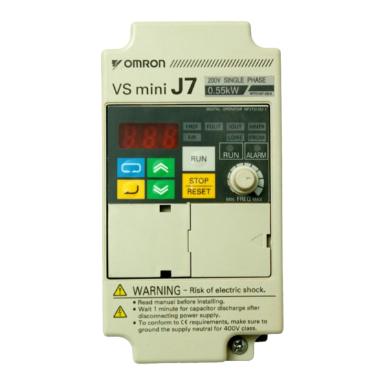
    Einbauabmessungen min. 30 mm min. 30 mm Luft Luft 4. Inbetriebnahme und Testlauf Anzeigen (Einstellung/ Datenanzeige Anzeige) Tasten FREQ-Einsteller Anzeige Bezeichnung Funktion Datenanzeige Anzeige relevanter Daten wie Frequenzsollwert, Ausgangsfrequenz und eingestellte Parameterwerte. FREQ-Einsteller Einstellung des Frequenzsollwerts auf einen zwischen 0 Hz und der Maximalfrequenz liegenden Wert.
  • Seite 35: Schritt 1 - Grundüberprüfungen

    Anzeige Bezeichnung Funktion LO/RE-Anzeige Wenn diese Anzeige leuchtet, kann ausgewählt werden, ob der Betrieb des Frequenzumrichters über die digitale Bedienkonsole oder gemäß der eingestellten Parameter erfolgt. Hinweis: Der Status dieser Einstellung kann nur bei laufendem Frequenzumrichterbetrieb angezeigt werden. RUN-Befehle werden ignoriert, solange diese Anzeige leuchtet.
  • Seite 36: Schritt 3 - Initialisieren Der Parameter

    RUN-Anzeige: blinkt. ALARM-Anzeige: aus Sonstige Anzeigen (Einstellung/Anzeige): FREF, FOUT oder IOUT leuchtet. Datenanzeige: zeigt die entsprechenden Daten (Frequenzsollwert, Ausgangsfrequenz oder Ausgangsstrom) an. Trat beim Einschalten der Versorgungsspannung ein Fehler auf, werden die Details des Fehlers angezeigt. Konsultieren Sie in diesem Fall die Bedienungsanleitung, und ergreifen Sie die erfor- derlichen Maßnahmen.
  • Seite 37: Schritt 5 - Einstellung Der Motornennfrequenz

    Schritt 5 – Einstellung der Motornennfrequenz Die Motornennfrequenz gibt die maximale Betriebsfrequenz des Motors an. Der Frequenzumrichter benötigt diese Angabe, um den Motor ordnungsgemäß ansteuern zu können. Lesen Sie die auf dem Typenschild des Motors angegebene Nennfrequenz (Hz) ab, und stellen Sie die Parameter n09 und n11 auf diesen Wert.
  • Seite 38: Parameterübersicht

    5. Parameterübersicht Parameter-Nr. Beschreibung Bereich Standardeinstellung 0 bis 9 Parameterschutz: 0: Beschränkter Zugriff auf die Parameter 1: Vollständiger Zugriff auf die Parameter 8: Zurücksetzen der Parameter auf die Werkseinstellungen Befehlsquelle: 0 bis 2 0: Bedientasten 1: Steuerklemmen 2: Kommunikation (Option) Frequenzsollwertquelle: 0 bis 4, 6 0: FREQ-Einsteller...
  • Seite 39 Multifunktionseingänge Multifunktionsausgänge Einstellung Funktion Einstellung Funktion Multistep-Drehzahlsollwert 2 Frequenzumrichter bereit Multistep-Drehzahlsollwert 3 Unterspannung Tippbetrieb Analoger Überwachungsausgang Externe Endstufensperre (Schließer) Einstellung Funktion Externe Endstufensperre (Öffner) Ausgangsfrequenz Umschaltung Lokal / Dezentral Ausgangsstrom *1 Eine vollständige Liste finden Sie in der Bedienungsanleitung. Parametereinstellungen (Beispiel) Änderungen verwerfen Nach etwa einer Sekunde...
  • Seite 40: Überwachungsanzeige

    6. Überwachungsanzeige Der Frequenzumrichter VS Mini J7 ermöglicht die kontinuierliche Anzeige bestimmter Betriebspara- meter (z. B. Ausgangsstrom oder Status der Multifunktionseingänge). Diese Überwachung erfolgt mithilfe der „U“-Parameter. Datenanzeige Tastenfolge Anzeige Erläuterung (Beispiel) Spannung EIN Drücken Sie wiederholt die Betriebsartentaste, bis die MNTR- Anzeige leuchtet.
  • Seite 41: Fehler Und Alarme

    Eingangs-/Ausgangsklemmenstatus Eingangsklemmenstatus 1: Klemme S1 ist auf EIN gesetzt 1: Klemme S2 ist auf EIN gesetzt 1: Klemme S3 ist auf EIN gesetzt 1: Klemme S4 ist auf EIN gesetzt 1: Klemme S5 ist auf EIN gesetzt Nicht verwendet Ausgangsklemmenstatus 1: Kontakt MA-MC ist geschlossen Nicht verwendet 7.
  • Seite 43 VARIADOR DE VELOCIDAD J7 Guía rápida 1. Cableado 2. Terminales del circuito de control 3. Instalación 4. Inicio y prueba de funcionamiento 5. Lista rápida de parámetros 6. Monitorización 7. Fallos y alarmas...
  • Seite 44 1. Cableado PUENTE 3G3JV PFI @ Filtro de ruido R/L1 U/T1 S/L2 V/T2 T/L3 W/T3 Trifásica de 200 V c.a.; monofásica de 200 V c.a. (ver nota 1) Salida de contacto multifuncional Marcha directa/parada Entrada multifuncional 1 (S2) Entrada multifuncional 2 (S3) Común Entrada multifuncional 3 (S4) Entrada multifuncional 4 (S5)
  • Seite 45 2. Terminales del circuito de control Símbolo Nombre Función Nivel de la señal Entrada S1 Marcha directa/Parada Marcha directa: ON, Parada: OFF Fotoacoplador de 8 mA a 24 V c.c. Entrada multifuncional 1 Configurada mediante el parámetro n36 (Inversa/Parada) Entrada multifuncional 2 Configurada mediante el parámetro n37 (Fallo externo: NA) Entrada multifuncional 3...
  • Seite 46 3. Instalación Dos orificios de 5 de diá. Línea y protección Dimensiones (mm) Tensión Modelo recomendada nominal J7AZ MCCB (A) Hilo (mm²) Trifásica de 20P1 200 V c.a. 20P2 20P4 20P7 21P5 22P2 24P0 Monofásica de B0P1 200 V c.a. B0P2 B0P4 B0P7...
  • Seite 47 Dimensiones Modelo Filtro J7AZ 3G3JV- 40P2 PFI3005-SE 111 40P4 40P7 PFI3010-SE 111 41P5 42P2 43P0 PFI3020-SE 144 44P0 Instalación del filtro de ruido y J7 Cable Cable apantallado apantallado Panel de control Panel de control Placa de mon- Placa de mon- Filtro trifásico Filtro trifásico taje metálica...
  • Seite 48 Dimensiones de instalación 30 mm 30 mm (1,18 pulg.) (1,18 pulg.) O MÁS O MÁS AIRE AIRE 4. Inicio y prueba de funcionamiento Indicadores (indicadores de elemento de Display de datos selección/monitorización) Potenciómetro de ajuste Teclas de frecuencia (FREQ) Aspecto Nombre Función Display de datos...
  • Seite 49 Aspecto Nombre Función Indicador de local/ Mientras este indicador esté iluminado, se puede seleccionar la operación del remota (LO/RE) variador a través del operador digital o según los parámetros seleccionados. Nota: El estado de este indicador sólo puede monitorizarse mientras el variador esté...
  • Seite 50 2-2 Si el display es normal al conectar la alimentación, presentará la siguiente información: indicador RUN: parpadea indicador ALARM: apagado Indicadores de selección/monitorización: FREF, FOUT o IOUT iluminado. Display de datos: muestra los datos correspondientes al indicador iluminado. En caso de haberse producido un fallo, presentará los detalles del mismo. En tal caso, consulte el manual del usuario y adopte las medidas pertinentes.
  • Seite 51 Paso 5 – Configuración de la frecuencia nominal del motor Es la frecuencia máxima a la que puede funcionar el motor, y permite al J7 controlarlo correctamente. Lea la frecuencia nominal (en Hz) en la placa de referencia del motor, y especifique este valor en los parámetros n09 y n11.
  • Seite 52 5. Lista rápida de parámetros Nº de Descripción Intervalo Valor predeterminado parámetro Acceso al parámetro: 0 a 9 0: acceso limitado al parámetro 1: acceso pleno al parámetro 8: inicializar parámetro predeterminado de fábrica Selección del comando Run: 0 a 2 0: operador digital 1: terminal del circuito de control 2: comunicaciones (opcional)
  • Seite 53 Entradas multifuncionales Salidas multifuncionales Valor Función Valor Función Referencia de multivelocidad 3 Infratensión en curso Comando Marcha por impulsos Ajustes de funciones de salida analógica Base block externo (NA) Valor Función Base block externo (NC) Frecuencia de salida Selección local/remota Corriente de salida *1 Consulte en el manual del usuario los valores completos Ejemplo de configuración de parámetros...
  • Seite 54 6. Monitorización El variador de velocidad J7 permite monitorizar diversas situaciones, como por ejemplo la corriente de salida y el estado de las entradas multifunción. La monitorización se realiza mediante los parámetros “U”. Secuencia de Ejemplo de Indicador Explicación teclas display Alimentación ON Pulse varias veces la tecla Modo hasta que se ilumine el...
  • Seite 55 Estado de terminal de entrada/salida Estado de terminal de entrada 1: Terminal S1 “cerrado” 1: Terminal S2 “cerrado” 1: Terminal S3 “cerrado” 1: Terminal S4 “cerrado” 1: Terminal S5 “cerrado” No se utiliza Estado de terminal de salida 1: Terminal MA-MC “cerrado” No se utiliza 7.
  • Seite 57 VS MINI J7 Guide de démarrage rapide 1. Câblage 2. Bornes de circuit de contrôle 3. Installation 4. Démarrage et essai 5. Aperçu de la liste des paramètres 6. Moniteurs 7. Erreurs et alarmes...
  • Seite 58 1. Câblage CAVALIER DE 3G3JV PFI @ COURT CIRCUIT Filtre antiparasite R/L1 U/T1 S/L2 V/T2 T/L3 W/T3 Triphasé 200 Vc.a. monophasé 200 Vc.a. (voir remarque 1) Sortie de contact multifonction Avant/arrêt Entrée multifonction 1 (S2) Entrée multifonction 2 (S3) Commun Entrée multifonction 3 (S4) Entrée multifonction 4 (S5) Commun d'entrée de séquence...
  • Seite 59 2. Bornes de circuit de contrôle Symbole Fonction Niveau du signal Entrée Avant/arrêt Marche sur ON/Arrêt sur OFF Optocoupleur 8 mA à 24 Vc.c. Entrée multifonction 1 Définie par le paramètre n36 (Inversion/arrêt) Entrée multifonction 2 Définie par le paramètre n37 (Erreur externe : NO) Entrée multifonction 3 Définie par le paramètre n38...
  • Seite 60 3. Installation Deux trous de 5 de diamètre Dimensions (mm) Conseil d’alimentation Tension Modèle nominale J7AZ MCCB (A) Câble (mm²) Triphasé 20P1 200 Vc.a. 20P2 20P4 20P7 21P5 22P2 24P0 Monophasé B0P1 200 Vc.a. B0P2 B0P4 B0P7 B1P5 Triphasé 40P2 400 Vc.a.
  • Seite 61 Dimensions Modèle Filtre J7AZ 3G3JV- 40P2 PFI3005-SE 111 40P4 40P7 PFI3010-SE 111 41P5 42P2 43P0 PFI3020-SE 144 44P0 Installation du filtre d’entrée et J7 Câble Câble blindé blindé Panneau de commande Panneau de commande Plaque de Plaque de Filtre Filtre montage en montage en Schaffner...
  • Seite 62: Dimensions De Montage

    Dimensions de montage 30 mm 30 mm (1,18 in.) (1,18 in.) OU PLUS OU PLUS 4. Démarrage et essai Voyants (voyants de réglage / Affichage des données surveillance) Touches Ajusteur FREQ Présentation Fonction Affichage des Affiche les données pertinentes, telles que la référence de fréquence, données la fréquence de sortie et les valeurs définies des paramètres.
  • Seite 63 Présentation Fonction Voyant LO/RE Le fonctionnement du variateur via la console numérique ou selon les paramètres définis peut être sélectionné quand ce voyant est allumé. Remarque : Le statut de cet indicateur ne peut être surveillé que lorsque le variateur fonctionne. Toute entrée de commande RUN est ignorée quand l’indicateur est allumé...
  • Seite 64 voyant RUN : clignote Voyant ALARM : off Voyants réglage/surveillance : FREF, FOUT ou IOUT est allumé. Affichage des données : affiche les données correspondant au voyant allumé. Lorsqu’une erreur s’est produite, les détails de l’erreur s’affichent. Dans ce cas, consultez le manuel de l’utilisateur et prenez les mesures nécessaires.
  • Seite 65 Etape5 – Définition de la fréquence nominale du moteur Il s’agit de la fréquence maximale à laquelle peut tourner le moteur. Elle permet également au J7 de contrôler correctement le moteur. Vérifiez la fréquence nominale (en Hz) sur la plaque d’identification du moteur et saisissez-la pour les paramètres n09 et n11.
  • Seite 66 5. Aperçu de la liste des paramètres N° du Description Plage Par défaut paramètre Accès aux paramètres : 0 à 9 0: Accès limité au paramètre 1: Accès complet au paramètre 8: Initialisation du paramètre en usine Sélection de la commande d'exécution : 0 à...
  • Seite 67 Entrées multifonctions Sorties multifonctions Valeur Fonction Valeur Fonction Référence de vitesse à étapes multiples 3 Sous-tension en cours Commande pas à pas Fonctions de sortie analogique Commande du circuit externe (NO) Valeur Fonction Commande du circuit externe (NC) Fréquence de sortie Sélection Local/distant Courant de sortie *1 Consultez le manuel de l’utilisateur pour connaître toutes les valeurs définies...
  • Seite 68 6. Moniteurs Le Vs mini J7 vous permet de surveiller plusieurs situations telles que le courant de sortie et le statut des entrées multifonctions. Cette surveillance est possible grâce aux paramètres « U ». Exemple Séquence clé Voyant Explication d’affichage Sous tension Appuyez plusieurs fois sur la touche Mode jusqu’à...
  • Seite 69: Erreurs Et Alarmes

    État de la borne d’entrée/sortie État de la borne d'entrée 1: La borne S1 est « fermée » 1: La borne S2 est « fermée » 1: La borne S3 est « fermée » 1: La borne S4 est « fermée » 1: La borne S5 est «...
  • Seite 71: Guida Di Avvio Rapido

    VS MINI J7 Guida di avvio rapido 1. Cablaggio 2. Terminali circuito di controllo 3. Installazione 4. Avvio e collaudo 5. Elenco dei parametri principali 6. Funzioni di monitoraggio 7. Errori e allarmi...
  • Seite 72 1. Cablaggio BARRA DI CORTOCIRCUITO 3G3JV PFI @ Filtro antidisturbo R/L1 U/T1 S/L2 V/T2 T/L3 W/T3 Trifase 200 V c.a. monofase 200 V c.a. (vedere nota 1) Uscita a contatto multifunzione Marcia avanti/Arresto Ingresso multifunzione 1 (S2) Ingresso multifunzione 2 (S3) Comune Ingresso multifunzione 3 (S4) Ingresso multifunzione 4 (S5)
  • Seite 73 2. Terminali circuito di controllo Simbolo Descrizione Funzione Livello del segnale Ingresso S1 Marcia avanti/Arresto Fotoaccoppiatore 8 mA a 24 V c.c. Ingresso multifunzione 1 Impostato con il parametro n36 (Marcia indietro/Stop) Ingresso multifunzione 2 Impostato con il parametro n37 (Errore esterno: NA) Ingresso multifunzione 3 Impostato con il parametro n38...
  • Seite 74 3. Installazione Due fori diametro 5 Raccomandazioni per Dimensioni (mm) Tensione Modello l'alimentazione nominale J7AZ MCCB (A) Filo (mm²) Trifase 20P1 200 V c.a. 20P2 20P4 20P7 21P5 22P2 24P0 Monofase B0P1 200 V c.a. B0P2 B0P4 B0P7 B1P5 Trifase 40P2 400 V c.a.
  • Seite 75 Dimensioni Modello Filtro J7AZ 3G3JV- 40P2 PFI3005-E 40P4 40P7 PFI3010-E 41P5 42P2 43P0 PFI3020-E 44P0 Installazione del filtro antidisturbo e del J7 Cavo Cavo schermato schermato Pannello di comando Pannello di comando Piastra metallica Piastra metallica Trifase con Trifase con di montaggio di montaggio filtro RFI...
  • Seite 76: Dimensioni Di Montaggio

    Dimensioni di montaggio 30 mm 30 mm (1,18”) O (1.18”) O SUPERIORE SUPERIORE ARIA ARIA 4. Avvio e collaudo Spie (spie dei parametri da Visualizzazione dati impostare/ monitorare) Tasti Potenziometro FREQ Aspetto Nome Funzione Visualizzazione dati Visualizza dati rilevanti, quali frequenza di riferimento, frequenza di uscita e valori impostati per parametri.
  • Seite 77 Aspetto Nome Funzione Spia LO/RE Quando questa spia è accesa, è possibile selezionare se il funzionamento dell'inverter è controllato mediante la console di programmazione o in base ai parametri impostati. Nota Lo stato di questa spia può essere monitorato solo quando l'inverter è...
  • Seite 78 2-2 In caso di funzionamento normale, una volta collegata l'alimentazione il display apparirà come segue: Spia di MARCIA: lampeggiante Spia di ALLARME: spenta Spie dei parametri da impostare/monitorare: FREF, FOUT o IOUT accesa. Visualizzazione dati: visualizzazione dei dati relativi alla spia accesa. Se si è...
  • Seite 79 Fase 5 – Impostazione della frequenza nominale del motore. Questo valore rappresenta la frequenza massima di funzionamento del motore. La sua impostazione consente al J7 di controllare correttamente il motore. Leggere il valore della frequenza nominale (in Hz) sulla targa del motore e inserirlo nei parametri n09 e n11. Fase 6 –...
  • Seite 80 5. Elenco dei parametri principali N. parametro Descrizione Range (Ambito) Valore predefinito Da 0 a 9 Accesso ai parametri 0: Accesso limitato ai parametri 1: Accesso completo ai parametri 8: Inizializzazione parametri di fabbrica Selezione comando di marcia Da 0 a 2 0: Console di programmazione: 1: Terminale del circuito di controllo 2: Comunicazione (opzionale)
  • Seite 81 Ingressi multifunzione Uscite multifunzione Valore Funzione Valore Funzione Multivelocità di riferimento 2 Inverter pronto Multivelocità di riferimento 3 Caduta di tensione in corso Comando a impulsi Funzioni uscita analogica Blocco delle basi esterno (NA) Valore Funzione Blocco delle basi esterno (NC) Frequenza di uscita Selezione locale/remota Corrente d'uscita...
  • Seite 82: Funzioni Di Monitoraggio

    6. Funzioni di monitoraggio Il J7 permette di monitorare varie condizioni, quali la corrente di uscita e lo stato degli ingressi multifunzione. Tale monitoraggio viene effettuato mediante i parametri a "U". Esempio di Sequenza di tasti Spia Spiegazione visualizzazione Accensione Premere ripetutamente il tasto di selezione modalità...
  • Seite 83: Errori E Allarmi

    Stato terminali d'ingresso/uscita Stato terminali di ingresso 1: Il terminale S1 è "chiuso" 1: Il terminale S2 è "chiuso" 1: Il terminale S3 è "chiuso" 1: Il terminale S4 è "chiuso" 1: Il terminale S5 è "chiuso" Non utilizzato Stato terminali di uscita 1: Il terminale MA-MC è...
  • Seite 85 VS MINI J7 Breve Guia de Introdução 1. Cablagem 2. Terminais do circuito de controlo 3. Instalação 4. Arranque e funcionamento experimental 5. Breve lista de parâmetros 6. Monitores 7. Falhas e alarmes...
  • Seite 86 1. Cablagem SHUNT 3G3JV PFI @ Filtro de ruído R/L1 U/T1 S/L2 V/T2 T/L3 W/T3 trifásico 200 V CA monofásico 200 V CA (ver nota 1) Saída de contacto multifunções Directo/Paragem Entrada multifunções 1 (S2) Entrada multifunções 2 (S3) Comum Entrada multifunções 3 (S4) Entrada multifunções 4 (S5) Comum de entrada...
  • Seite 87 2. Terminais do circuito de controlo Símbolo Nome Função Nível do sinal Entrada S1 Directo/Paragem Directo em ON/ Paragem em OFF Fotoacoplador 8 mA a 24 V CC Entrada multifunções 1 Definida pelo parâmetro n36 (Inverso/Paragem) Entrada multifunções 2 Definida pelo parâmetro n37 (Falha externa: Entrada multifunções 3 Definida pelo parâmetro n38 (Reset de falha) Entrada multifunções 4...
  • Seite 88: Instalação

    3. Instalação Dois orifícios de 5 dia Recomendações de Dimensões (mm) Tensão Modelo alimentação nominal J7AZ MCCB (A) Fio (mm²) Trifásica 20P1 200 V CA 20P2 20P4 20P7 21P5 22P2 24P0 Monofásica B0P1 200 V CA B0P2 B0P4 B0P7 B1P5 Trifásica 40P2 400 V CA...
  • Seite 89 Dimensões Modelo Filtro J7AZ 3G3JV- 40P2 PFI3005-SE 111 40P4 40P7 PFI3010-SE 111 41P5 42P2 43P0 PFI3020-SE 144 44P0 Instalação do filtro de ruído e J7 Cabo Cabo blindado blindado Painel de controlo Painel de controlo Placa de fixação Placa de fixação Filtro Filtro de metal...
  • Seite 90: Dimensões De Montagem

    Dimensões de montagem 30mm 30mm (1,18 in.) (1,18 in.) OU MAIS OU MAIS 4. Arranque e funcionamento experimental Indicadores (Indicadores dos itens de Visor de apresentação monitorização/ de dados definição) Teclas Regulador de FREQ Aspecto Nome Função Visor de apresenta- Apresenta itens de dados relevantes, tais como a frequência ção de dados de referência, a frequência de saída e valores de parâmetros definidos.
  • Seite 91 Aspecto Nome Função Indicador LO/RE É possível seleccionar o funcionamento do Variador utilizando a Consola digital ou de acordo com os parâmetros definidos quando este indicador está iluminado. Nota: Só é possível monitorizar o estado deste indicador quando o Varia- dor está...
  • Seite 92 Indicador ALARM: desligado Indicadores de monitorização/definição: FREF, FOUT ou IOUT está iluminado. Visor de apresentação de dados: apresenta os dados correspondentes ao indicador iluminado. Quando ocorre uma falha, os detalhes da falha são apresentados. Neste caso, consulte o manual do utilizador e tome as medidas necessárias. Passo 3 –...
  • Seite 93 Passo 5 – Definir a frequência nominal do motor Trata-se da frequência máxima de funcionamento do motor e permite ao J7 controlar de forma cor- recta o motor. Consulte a indicação de frequência nominal (em Hz) na placa de identificação do motor e introduza estas informações nos parâmetros n09 e n11.
  • Seite 94 5. Breve lista de parâmetros Nº do Descrição Intervalo Predefinição parâmetro Acesso a parâmetros: 0 a 9 0: Acesso limitado a parâmetros 1: Acesso total a parâmetros 8: Inicialização dos parâmetros Selecção do comando de arranque: 0 a 2 0: Consola digital 1: Terminal do circuito de controlo 2: Comunicação (opção) Selecção de frequência de referência:...
  • Seite 95 Entradas multifunções Saídas multifunções Valor Função Valor Função Velocidade de referência multi-step 2 Variador preparado Velocidade de referência multi-step 3 Subtensão em curso Comando por impulsos Funções de saída analógica Base block externo (NO) Valor Função Base block externo (NC) Frequência de saída Selecção local/remota Corrente de saída...
  • Seite 96 6. Monitores O VS mini J7 permite monitorizar várias condições, tais como a corrente de saída e o estado das entradas multifunções. Esta monitorização é efectuada através dos parâmetros “U”. Sequência Indicador Exemplo de visor Explicação de teclas Ligado Prima a tecla de modo repetidamente até que o indicador MNTR fique iluminado.
  • Seite 97 Estado do terminal de saída/entrada Estado do terminal de entrada 1: O terminal S1 está “fechado” 1: O terminal S2 está “fechado” 1: O terminal S3 está “fechado” 1: O terminal S4 está “fechado” 1: O terminal S5 está “fechado” Não utilizado Estado do terminal de saída 1: O terminal MA-MC está...
  • Seite 99 VS MINI J7 Инструкция по быстрому запуску 1. Подключение цепей 2. Клеммы схемы управления 3. Монтаж 4. Пробный запуск 5. Список основных параметров 6. Контролируемые параметры 7. Коды неисправностей...
  • Seite 100 1. Подключение цепей 3G3JV PFI @ Перемычка Фильтр подавления помех R/L1 U/T1 S/L2 V/T2 T/L3 W/T3 200 В~, 3-фазн. 200 В~, 1-фазн. (см. прим. 1) Многофункциональные дискретные (контакторные) Вперед/стоп выходы Многофункцион. вход 1 (S2) Многофункцион. вход 2 (S3) Общая цепь Многофункцион.
  • Seite 101 2. Клеммы схемы управления Обознач. Название Функция Уровень сигнала Вход S1 Вперед/Стоп ВКЛ: Вперед / ВЫКЛ: Стоп Оптопара, 8 мA при 24 В= S2 Многофункциональный вход 1 Определяется параметром n36 (Назад/Стоп) S3 Многофункциональный вход 2 Определяется параметром n37 (Внешняя ошибка: NO) S4 Многофункциональный...
  • Seite 102 3. Монтаж Два отверстия, диаметр 5 Размеры (мм) Рекомендуемые номиналы Номинальное Модель Провод напряжение J7AZ MCCB (A) (мм 200 В~ 20P1 3-фазное 20P2 20P4 20P7 21P5 22P2 24P0 200 В~ B0P1 1-фазное B0P2 B0P4 B0P7 B1P5 400 В~ 40P2 3-фазное 40P4 40P7 41P5...
  • Seite 103 Размеры Модель Фильтр J7AZ 3G3JV- 40P2 PFI3005-SE 111 40P4 40P7 PFI3010-SE 111 41P5 42P2 43P0 PFI3020-SE 144 44P0 Монтаж фильтра подавления помех и инвертора J7 Экранированный Экранированный кабель кабель Панель управления Панель управления Металлическая Металлическая монтажная пла- монтажная пла- 3-фазный фильтр 3-фазный...
  • Seite 104: Пробный Запуск

    Монтажные размеры 30мм (1.18”) 30мм (1.18”) или больше или больше Воздушное пространство Воздушное пространство 4. Пробный запуск Индикаторы (Настраиваемых/ Информационный контролируемых дисплей параметров) Клавиши Ручка регулировки FREQ Внешний вид Название Назначение Информационный Отображение значений соответствующих параметров, например, дисплей опорной частоты, выходной частоты и настраиваемых параметров. Ручка...
  • Seite 105 Внешний вид Название Назначение Индикатор LO/RE Когда светится этот индикатор, можно выбрать либо управление инвертором с помощью Цифровой панели управления, либо работу инвертора в соответствии с настроенными параметрами. Примечание: Когда инвертор работает в режиме управления двигателем, состояние этого индикатора изменить нельзя.
  • Seite 106 Шаг 2 – Подача напряжения питания и проверка состояния дисплея 2-1 Выполнив предварительную проверку (Шаг 1), подайте на входные силовые клеммы напряжение питания. 2-2 В нормальном режиме при поданном напряжении дисплей выглядит следующим образом: индикатор RUN: мигает индикатор ALARM: выключен индикаторы...
  • Seite 107 Нажимаемые Пример Индикатор Пояснение клавиши дисплея Нажмите клавишу "Ввод". На дисплее отобразится значение параметра n32. С помощью клавиш увеличения/уменьшения задайте номинальный ток двигателя. Дисплей будет мигать. Нажмите клавишу "Ввод", чтобы подтвердить установленное значение, дисплей перестанет мигать. Приблиз. через 1 с На...
  • Seite 108 СИГНАЛ ЗАДАНИЯ ОПОРНОЙ ОПОРНАЯ ЧАСТОТА ЧАСТОТЫ (0 ... +10В) (ЗАДАНИЕ СКОРОСТИ) +12В, 20мА FC(0В) 5. Список основных параметров Номер Значение по Описание Диапазон значений параметра умолчанию Доступ к параметрам: 0 ... 9 0: Ограниченный доступ к параметрам 1: Полный доступ к параметрам 8: Инициализация...
  • Seite 109 Номер Значение по Описание Диапазон значений параметра умолчанию Несущая частота 1 ... 4 (2.5 - 10 кГц) Зависит от модели 7 ... 9 (пропорционально выходной частоте) Ток при торможении с подпиткой 0 ... 100% постоянным током Продолжительность торможения с 0.0 ... 25.5 сек 0.5 сек...
  • Seite 110 Пример настройки параметра Отмена значения Приблиз. через 1 с. Нажимаемые Индикатор Пример дисплея Пояснение клавиши Включение питания. Нажмите клавишу "Режим" несколько раз, пока не начнет светиться индикатор PRGM. С помощью клавиш увеличения/уменьшения выберите требуемый параметр. Нажмите клавишу "Ввод". Будет отображено значение выбранного...
  • Seite 111 6. Контролируемые параметры В инверторе Vs mini J7 предусмотрена возможность контроля различных параметров, например, выходного тока или состояния многофункциональных входов. Для контроля различных параметров предназначены параметры группы "U". Нажимаемые Индикатор Пример дисплея Пояснение клавиши Включение питания Нажмите несколько раз клавишу "Режим", пока не будет...
  • Seite 112: Коды Неисправностей

    Состояние входных/выходных клемм Состояние входных клемм 1: Цепь клеммы S1 “замкнута” 1: Цепь клеммы S2 “замкнута” 1: Цепь клеммы S3 “замкнута” 1: Цепь клеммы S4 “замкнута” 1: Цепь клеммы S5 “замкнута” Не используется Состояние выходных клемм 1: Цепь клеммы MA-MC “замкнута” Не...
  • Seite 113 Код Описание неисправности неисправ- Возможная причина и способ устранения (ошибки) ности Внешняя ошибка Проверьте цепи клемм схемы управления. Подан сигнал внешней ошибки. Для многофункционального дискретного входа выбрана функция 3 или 4. Эту ошибку можно сбросить только после снятия сигнала "Ход" (Run).
  • Seite 116 Tel: +34 913 777 900 www.omron.fi www.omron.nl www.omron.es For the Middle East, Africa and other countries in Eastern Europe, Tel: +31 (0) 23 568 13 00 www.europe.omron.com Manufacturer YASKAWA ELECTRONIC CORPORATION YASKAWA In the event that the end user of this product is to be the military and said product is to be employed in any weapons sxstems or the manufacture thereof, the export will fall under the relevand regulations as stipulated in the Foreign Exchange and Foreign Trade Regulations.

Diese Anleitung auch für:

Cimr-j7az

Inhaltsverzeichnis